manuals.online logo
Brands
  1. Home
  2. •
  3. Brands
  4. •
  5. roco
  6. •
  7. Toy
  8. •
  9. roco 74263 User manual

roco 74263 User manual

Bitte bewahren Sie die Verpackung des Wagens sorgfältig auf. Beim
Abstellen des Wagens bietet sie Ihrem Modell den besten Schutz. Ein
mit den beigelegten Zurüstteilen aufgerüsteter Wagen passt nur be-
dingt wieder in die Originalverpackung hinein, da diese aus Gründen
der Transportsicherung sehr eng sein muss. Es empehlt sich, die Ori-
ginalverpackung an gewissen Stellen mit einem scharfen Messer aus-
zuschneiden. Kleinere Teile des Modells, wie z.B. Puffer, sind wegen
Detailtreue als aufgerüstete Steckteile ausgeführt und sind daher mit
dem Grundkörper nicht ganz fest verbunden. Beim selbstverschulde-
ten Verlust möchten Sie bitte ein solchesTeil neu bestellen. ( In diesem
Fall können Sie diese Teile auf dem Ersatzteilweg nachbestellen, eine
Reklamation kann nicht geltend gemacht werden.) • Don't throw
your box in the dustbin. If your model is not in use this box will keep
it safe. If kits are mounted on a wagon it will be slightly tight when
placing it in the original box. This guarantees safe transport. It is th-
erefore recommanded to cut out certain parts of the original box. To
keep the model like the original, smaller parts (e.g. buffers) had been
manufactured separately from the body and are not tightly xed on
it. Therefore they probably can get lost. In this case you certainly may
reorder them but a complaint would not be acceptable. • Veuillez
conserver ce mode d’emploi ainsi que l’emballage en vue d’un futur
emploi. L’emballage se prête particulièrement bien pour stocker et
protêger votre modèle lorqu’il n’est pas en service. • Un wagon
entièrement êquipê de ses pièces de nition ne rentre plus dans son
emballage qu’après avoir dégagé la place nécessaire à l’aide d’un
coûteau n et bien guisé aux endroits cù sont montés ces piéces.
La stabilité et la sécurite de l’emballage lors du transport du modèle
de l’usine à votre detallant (ou même à vous) impose une réduction
au stricte minimum de toute place découpée et non utilisée, raison
pour laquelle ces d´coupes ne peuvent malheureusement pas être
aménagées déjà en usine. • Quelques petites pièces de nition (des
tampons p. e.) ne sont pas moulées d’un seul bloc avec leurs bases,
mais séparément rapportées en vue d’une réalisation plus détaillée.
Cela implique le risque de perte de ces composants. Dans ce cas, vous
pouvez commander ces pièces aux S.A.V. ROCO; nous ne pouvons
cependant pas donner suite à une r´clamation èventuelle à cause de
ces pièces perdues. • Heeft u uw model voorzien van alle inste-
ekdeeltjes, dan past deze niet meer precies in de doos. Na voorzichtig
passen snijdt u met een scherp mes eerst enige stukjes uit deze doos
en u heeft de beste bescherming voor uw kostbare model bereikt.
Bitte diese Beschreibung zum späteren Gebrauch aufbewahren! •
Please retain these instructions for further reference! • Pière de bien
vouloir con- server ce mode d’emploi en vue d’une future utilisation!
• Conservate queste istruczioni per un futuro utiliozzo! • Deze hand-
leiding altijd bewaren.
Achtung! Bei unsachgemäßem Gebrauch besteht Verletzungs- ge-
fahr durch funktionsbedingte scharfe Kanten und Spitzen • Atten-
tion! At an incorrect use there exists danger of hurting because of
cutting edgesand tips • Attention! II y a danger de blessure à un em-
ploi incorrect à cause des aiguilles et arêtes vives! • Voorzichtig! Bij
ondoelmatig gebruik bestaat verwondigsgevaar door scherpe zijkanten
en uitsteeksels! • Attenzione! Un inap-propriato uso comporta peri-
colo di ferimenti attraverso punte e spignoli taglienti! • Atencion! Un
emploe incorrecto puede causar causar heridas debido a las puntas y
aristas agudas! • Atencao! Por utilizacao incorrecta existe o perigo de
estragos, em virtude de cortes nas abas e nas pontas! • Bemaerk!
Ved ukorrekt brug kan de funktionsbetingede skarpe kanter og spidser
forvolde skade! • Proxoch! Hakatallhlh crhoh egkleiei kin
dunouz mkrot raumatismn, exaipax kopterwn akmwn kai
proexocwqn.
Änderungen von Konstruktion und Ausführung vorbehalten! • We re-
serve the right to change the construction and design! • Nous nous ré-
servons le droit de modier la construction et le dessin! • Ci riserviamo
il diritto di variare la costruzione e il design! • Verandering van model
en constructie voorbehouden.
CZ/SK - Návod na montáž stavebnice: Před stavbou pečlivě prostu-
dujte příložený návod s vyobrazením. Jednotlivé dily odděIte od licích
rámečku a začistěte modelářským nožem nebo pilníkem. Díly roztřídte
dle vyobrazení a postupně slepujte podle pořadi jednotlivých staveb-
nich kroku. K lepení používejte lepidla určená pro plastikové stavebince.
Ersatzteile zum Nachbestellen • Order nos for various spare parts •
Les références des pièces de rechange • Pezzi di ricambio • Onderdelen
Modelleisenbahn GmbH
A-5101 Bergheim
Plainbachstraße 4
Email: roco@roco.cc
Tel.: 00800 5762 6000
(kostenlos/ free of charge/ gratuit)
International: +43 820 200 668
(kostenpichtig/ chargeable / avec des coûts)
(Zum Ortstarif aus dem Festnetz / local tariff for landline / prix d‘une appel
locale depuis du téléphone xe - Mobilfunk / Mobile max. 0,42€/min.
incl. VAT)
AT|D|CH
8074263-920 III/19
74263
Ca. alle 30 Betriebsstunden ! • I.e. after it
has been in operation for 30 hours ! • Environ
tous les 30 heures d’exploitation ! • Na elke
30 diensturen !
ROCO Oiler
10906
Die abgebildeten Zurüstteile sind wie grasch dargestellt für
die Selbstmontage bestimmt. Dem Produkt können zusätzliche
kleine Teile beigepackt sein, die für eine andere vorbildgetreue
Aufrüstung bestimmt sind und beim vorliegenden Modell keine
Verwendung nden.
The enclosed parts are designated for self-assembling (please see
enclosed description). lt may occur that there are some parts ad-
ded which don’t t to your model but to another one so that they
should not get applied on this very model.
Les pièces de nition illustrèes sont à monter par le modèliste.
Le jeu de pièces peut comprendre d’autres pièces (non illustrées)
qui sont destinées à autres versions du modèle et qui sont superu
à la variante présente.
Kontakthalter /
Contact retainer /
60507882
für Beleuchtungseinbau / install lighting / installer éclairage
Beleuchtungssatz /
Lighting set / Kit d’eclairage intérieur
944701
Plattform - Führerstand /
Platform - driver‘s cab / Plateforme - cabine
00125300
6515
142272
Plattform mit Handbremse / Platform with
handbrake / Plate-forme avec frein à main
00125209
FLEISCHMANNROCO
*
*
*
*
* FLEISCHMANN
140575
6510
40270
40243
137025
133720
2.2.2.
Öffnen des Wagens
1.) Die Puffer vorsichtig etwas nach unten drücken, sodass sich
ein kleiner Spalt zwischen Wagenboden und Gehäuse bildet.
2.) Anschließend mit einer kleinen Pinzette die Rastnasen lösen.
Opening the coach
1.) Gently push the bumpers down slightly so that there is a
small gap between the bottom of the car and the housing.
2.) Then use a small pair of tweezers to release the detent.
Ouverture d’une voiture: D‘abord, sur un des côtés du wa-
gon, glissez unongle du pouce entre le châssis et la carrosserie.
Faites de même sur l‘autre côté du véhicule.
Kupplung vorsichtig in Pfeilrichtung abziehen. Neue
Kupplung in Pfeilrichtung einstecken, bis Halte-
klammern einrasten.
Carefully pull out the coupling in the direction of
the arrow. Insert the new coupling in the direction
of the arrow until it clips into position.
Sortir l’attelage en tirant prudemment dans le sens
de la èche. Enfoncer l’attelage dans le sens indi-
qué jusqu’à emboîtement des arrêtoires.
Zurüstbeutel /
Bag with accessories / Sachet d’accessoires
Kupplungsdeichsel /
Coupling assembly / L’attelage
1. 1mm
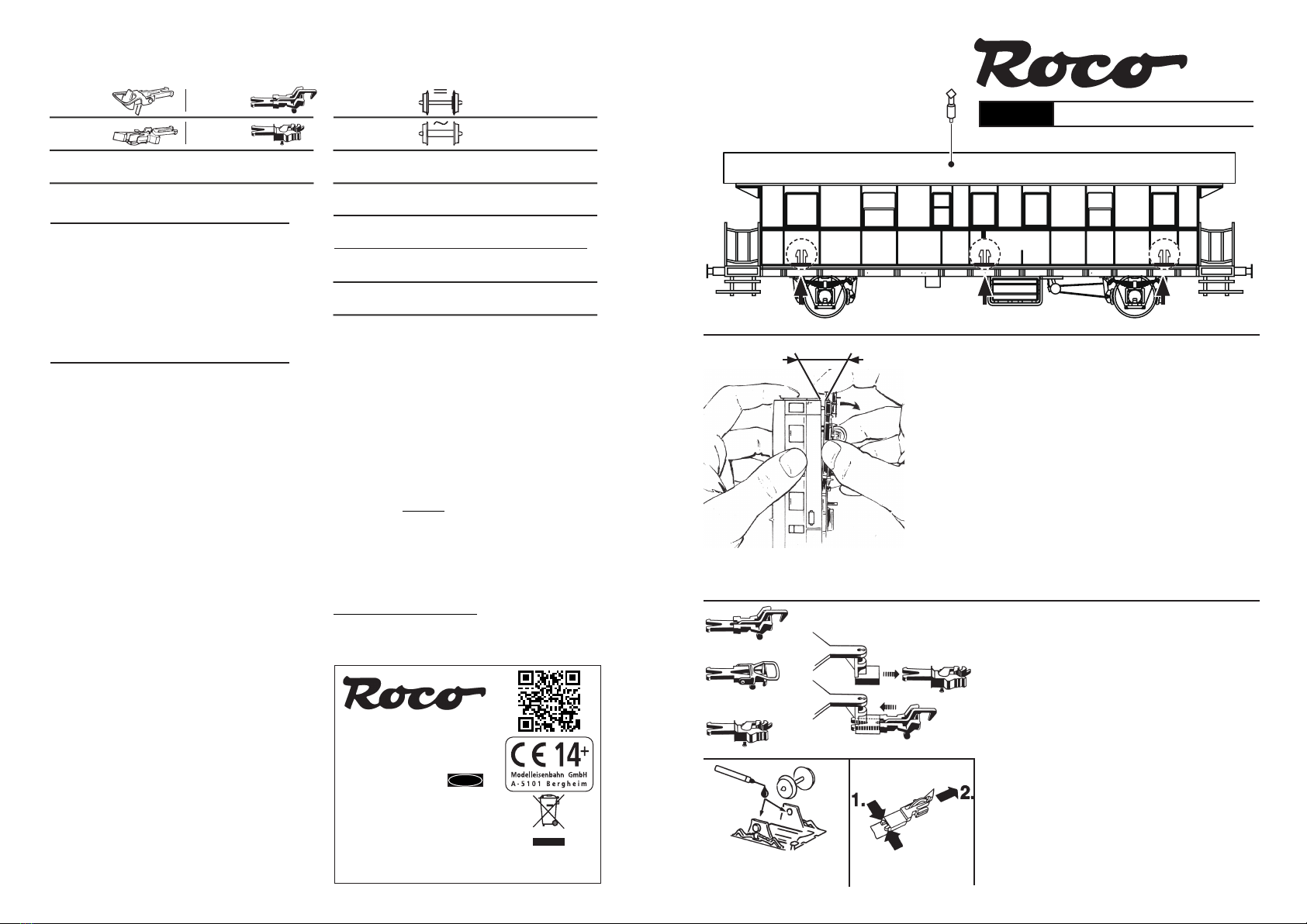
DCC-Funktions-DECODER
BESTIMMUNGSGEMÄSSER GEBRAUCH
Dieser DCC-Funktionsdecoder sorgt dafür, daß im
Gleichstrombetrieb die Stirnbeleuchtung des Fahr-
zeugs fahrtrichtungsabhängig weiß oder rot leuchtet
und die Zugzielanzeige über dem Führerstand einge-
schaltet ist. Im Digitalbetrieb sind die Funktionen des
Fahrzeugs mit der Digitaladresse 3 wie folgt einzeln
schaltbar:
F0 Stirnbeleuchtung
F1 Fahrgastraum / Innenbeleuchtung
F2 Beleuchtung Führerstand / Gepäckabteil
Funktionen und Einstellungen des Decoders können
mittels der CVs (CV = Conguration Variable) in wei-
ten Bereichen eingestellt werden, siehe CV-Tabelle
EIGENSCHAFTEN DES DCC-DECODERS
Der Funktionsdecoder ist ein Decoder zum Schalten
von Funktionen wie z.B. Licht für das DCC-System.
Er hat keinen Motoranschluss und wird vorzugswei-
se in Wagen bzw. Steuerwagen eingebaut, um hier
z.B. die Stirnbeleuchtung oder die Innenbeleuchtung
zu schalten. Auch auf normalen Gleichstromanlagen
ndet der Lichtwechsel vorbildgemäß statt. Der De-
coder verfügt über 4 Ausgänge, von denen zwei für
den weiß-roten Lichtwechsel an der Stirnseite vor-
eingestellt sind. Zwei weitere Ausgänge können über
die Funktionen F1 bzw. F2 des Steuergerätes aktiviert
werden. Diese Zuordnung ist für jeden Funktionsaus-
gang beliebig veränderbar. Jeder Ausgang kann mit
einem Strom von 200 mA belastet werden. Für jeden
Ausgang kann die Helligkeit individuell eingestellt
(gedimmt) werden, oder es kann auch ein Blinkbe-
trieb gewählt werden.
Maße (max.): 20 x 11 x 3,5 mm
Belastbarkeit je Aus-
gang (4 x) 200 mA
Adresse Elektronisch codierbar
Sonderfunktion Ein-/ausschaltbar
Licht Licht fahrtrichtungsab-
hängig
Lichtausgang Kurzschlussfest durch
Abschalten
Übertemperatur Schaltet ab bei Überhit-
zung
Senderfunktion Für RailCom1) bereits in-
tegriert
Bei Überschreiten des zulässigen Grenzwertes (ca.
100 °C auf Platine) wird die Motoransteuerung ab-
geschaltet. Zur Kenntlichmachung dieses Zustandes
blinken die Stirnlampen in schnellem Takt (ca. 5 Hz).
Die Wiedereinschaltung erfolgt automatisch mit einer
Hysterese von ca. 20 °C (also bei Absinken der Tempe-
ratur auf ca. 80 °C) nach ca. 30 sec.
HINWEIS: Digitale DCC-Decoder sind hochwertige
Erzeugnisse moderner Elektronik und mit besonderer
Sorgfalt zu behandeln:
• Berührung mit Flüssigkeiten (z. B. Öl, Wasser, Reini-
gunsmittel…) gefährden den DCC-DECODER.
• Unsachgemäße Behandlung mit metallischen Ge-
genständen (z. B. Schraubendreher, Pinzette…) kann
den DCC-DECODER mechanisch/elektrisch schädigen.
• Grobe Behandlung (z.B. Ziehen an den Litzen, Bau-
teile biegen) kann mechanische / elektrische Schäden
verursachen.
• Löten am DCC-DECODER kann zum Ausfall führen.
• Wegen Kurzschlussgefahr bitte unbedingt beach-
ten: Vor dem Berühren des DCC-DECODERS geerde-
ten Gegenstand anfassen (z. B. Heizkörper).
DCC-BETRIEB
Fahrzeuge mit eingebautem DCC-DECODER können
Sie z.B. mit den ROCO/FLEISCHMANN-Steuergerä-
ten LOK-BOSS (6865), PROFI-BOSS (686601), mul-
tiMAUS®, multiMAUS®PRO, WLAN-multiMAUS®,
TWIN-CENTER (6802), Z21®und z21®start nach der
NMRA-Norm betreiben. Welche DCC-Decoderfunkti-
onen Sie in welchem Umfang nutzen können, wird
vom Leistungsumfang des jeweiligen Steuergerätes
bestimmt.
Die in den jeweiligen Betriebsanleitungen unserer
Steuergeräte beschriebenen Funktionen sind mit dem
DCC-Funktionsdecoder voll nutzbar.
Mit Steuergeräten nach der NMRA-Norm ist system-
bedingt der gleichzeitige, kompatible Fahrbetrieb mit
mehreren Gleichstromfahrzeugen auf demselben
Gleisabschnitt nicht möglich (s. a. Anleitung der je-
weiligen Steuerung).
PROGRAMMIERUNG BEI DCC
Der DCC-Funktionsdecoder verfügt über eine Reihe
weiterer Einstellmöglichkeiten und Informationen, die
sein Verhalten bestimmen bzw. Rückschlüsse auf sein
Verhalten zulassen. Diese Informationen sind bzw.
werden in sogenannten CVs (CV = Conguration
Variable) gespeichert. Es gibt CVs, die nur eine ein-
Dzige Information (sog. „Byte“) speichern, aber auch
solche, die 8 Informationseinheiten (Bits) beinhalten.
Die Bits werden von 0 bis 7 durchnummeriert. Bei der
Programmierung brauchen Sie diese Kenntnisse. Die
benötigten CVs haben wir Ihnen aufgelistet (siehe
CV-Tabelle).
Die voreingestellten Grundwerte der CVs können mit
DCC-Steuergeräten nach NMRA-Norm umprogram-
miert werden, die die Programmierung „CV-direkt“
byte- und bitweise beherrschen. Auch die Program-
mierung einiger CVs über die Register-Programmie-
rung ist möglich. Ferner können alle CVs byteweise
auf dem Hauptgleis, unabhängig vom Programmier-
gleis, programmiert werden, soweit ihr Steuergerät
diese Art der Programmierung (POM - Program on
Main) beherrscht.
Weitere Informationen zu diesem Thema erhalten Sie
in den Gerätehandbüchern und Betriebsanleitungen
der jeweiligen Digitalsteuergeräte.
ANALOGBETRIEB
Sie wollen ihr ROCO DIGITALFahrzeug einmal auf ei-
ner Gleichstrom Anlage fahren lassen? Kein Problem,
im Lieferzustand ist die entsprechende CV-Variable
CV29 bereits so eingestellt, dass unsere DCC-Funk-
tionsdecoder auch auf „analogen“ Gleichstroman-
lagen fahren können. Natürlich können Sie dabei
nicht alle Highlights der digitalen Technik genießen.
Im Analogbetrieb funktioniert der Lichtwechsel weiss
/ rot und die Innenbeleuchtung des Fahrgastraumes.
HINWEIS: Zum ausschalten der Digitalanlage
Zum Ausschalten ihrer Modellbahn-Steuerung ak-
tivieren Sie bitte zuerst die Nothalt-Funktion des
Steuergerätes (siehe hierzu die Betriebsanleitung des
Steuergerätes). Anschließend kann der Netzstecker
der Stromversorgung gezogen werden.
RAILCOM1)
Der Funktionsdecoder in diesem Fahrzeug verfügt
über „RailCom1)“, d.h. er empfängt nicht nur Da-
ten von der Zentrale, sondern kann auch Daten an
eine RailCom1)-fähige Zentrale zurücksenden. Mehr
dazu entnehmen Sie bitte der Anleitung zu Ihrer
RailCom1)-fähigen Zentrale. Standardmäßig ist Rail-
Com1) ausgeschaltet (CV29, Bit 3=0). Für den Betrieb
an einer Zentrale, die nicht über RailCom1) verfügt,
empfehlen wir RailCom1) ausgeschaltet zu lassen.
Ausführliche Informationen nden Sie auch unter
www.zimo.at unter anderem in der Betriebsanleitung
„MX-Funktions-Decoder. pdf“, zu Decoder MX685.
DCC-Function-DECODER
SPECIFICATIONS
This DCC-DECODER ensures that in the DC mode,
the white or red headlights of the cab car are turned
on and off depending on the direction of travel and
that the destination indicator above the cab always
is turned on.
In digital mode, the functions of the cab car with the di-
gital address of 3, are individually switched as follows:
F0 headlights
F1 cabine lighting
F2 drivers cab lighting
Functions and settings of the decoder may be set in
wide ranges using the CVs (CV = Conguration vari-
able), see CV table.
PROPERTIES OF THE DCC-DECODER
The function decoder is designed for switching fun-
ctions, e. g. light within the DCC system. It has no
motor connections and should be installed mainly in
coaches, controlcab coaches and similar, to switch on
and off the headlights or illumination etc. It works
correctly on conventional DC-layouts as well. The de-
coder has 4 outputs, of which two are preadjusted
for alternating the red-white lighting at the frontside.
Two other outputs can be activated using the F1 or F2
functions of the controller. The assignment however
may be altered for each of the function outputs. Every
output is capable of providing current up to 200 mA.
For each output the brightness can be adjusted (dim-
med) individually, or else a blinking operation may be
selected.
Max. size: 20 x 11 x 3,5 mm
Load capacity (4 x) 200 mA
Address: Electronically codeable
Light Output: ON/Off switchable
Licht direction dependent
Lichtausgang Protected against short
circuit, switches off
Overheating: Switches off when over-
heated
Sender function: Already integrated for
RailCom1)
Power to the motor will be turned off once that tem-
perature exceeds 100°C. The headlights start ashing
rapidly, at about 5 Hz, to make this state visible to
the operator. Motor control will resume automatically
GB
1) RailCom «ist eingetragenes Warenzeichen / is a registered trademark of / est une marque déposée de» der Lenz GmbH, Giessen 2) Motorola «ist ein eingetragenes Warenzeichen der / is a protected trademark of / est une marque déposée de» Motorola Inc., Tempe-Phoenix (Arizona/USA)
after a drop in temperature of about 20°C, typically in
about 30 seconds.
Note:
The digital DCC-DECODERS are high value products
of the most modern electronics, and therefore must
be handled with the greatest of care: Liquids (i. e. oil,
water, cleaning uid ...) will damage the DCC-DE-
CODER.
• The DCC-DECODER can be damaged both electri-
cally or mechanically by unnecessary contact with
tools (twee zers, screwdrivers, etc.)
• Rough handling (i. e. pulling on the wires, bending
the components) can cause mechanical or electrical
damage
• Soldering onto the DCC-DECODER can lead to fai-
lure.
• Because of the possible short circuit hazard, please
note: Before handling the DCC-DECODER, ensure that
you are in contact with suitable earth (i. e. radiator).
DCC OPERATION
Locos with inbuilt DCC-DECODER can be used with
the ROCO/FLEISCHMANN-controllers LOK-BOSS
(6865), PROFI-BOSS (686601), multiMAUS®, mul-
tiMAUS®PRO, WLAN-mul-tiMAUS®, TWIN-CEN-
TER (6802), Z21®and z21®start conforming to the
NMRA standard. Which DCC-decoder functions
can be used within which parameters are fully de-
scribed in the respective operating instructions of
the respective controller. The prescribed functions
shown in the instruction leaets included with our
controllers are fully useable with the DCC-decoder.
The simultaneous, compatible running possibilities
with D.C. vehicles on the same electrical circuit is not
possible with DCC controllers conforming to NMRA
standards (see also manual of the respective control-
ler).
PROGRAMMING WITH DCC
The DCC-decoder enables a range of further settable
possibilities and information according to its charac-
teristics. This information is stored in so called CVs
(CV = Conguration Variable). There are CVs which
store only a single information, the so called Byte, and
others that contain 8 pieces of information (Bits). The
Bits are numbered from 0 to 7. When programming,
you will need that knowledge. The CVs required we
have listed for you (see CV table).
The programming of the CVs can be done with any
controller which is capable of the programming by
bits and bytes in mode ”CV direct“. The programming
of some CVs by registerprogramming is also possible.
Furthermore, all CVs can be programmed bytewise
on the main track, independently from the program-
mingtrack. However, this is possible only if your ap-
pliance is capable of this programmingmode (POM
- program on main).
Further information concerning that issue is given in
the respective manuals and operating instructions of
the digital controllers.
ANALOG OPERATION
You want to run your DCC-loco once in while on a DC
layout? No problem at all, because as delivered, we
have adjusted the respective CV29 in our decoders so
that they can run on ”analog“ layouts as well! Ho-
wever, you may not be able to enjoy the full range of
digital technique highlights.
ADVICE ON SWITCHING OFF
To switch off your model railway controller, rst of all
activate the emergency stop function of the controller
(see instructions with the controller). Then nally, pull
out the mains plug of the controller power supply;
otherwise you might damage the appliance. If you
ignore this critical advice, damage could be caused
to the equipment.
RAILCOM1)
The decoder in this car has „RailCom1)“, i.e. it does
not only receive data from the control center, but can
also return data to a RailCom1) capable control center.
For more information please refer to the manual of
your RailCom1) capable control center. By default Rail-
Com1) is switched off (CV29, Bit 3=0). For operation
at a control center that does not have RailCom1) capa-
bility, we recommend to leave RailCom1) switched off.
Detailed information are also available at www.zimo.
at amongst other in the operation manual “MX-Func-
tions-Decoder.pdf“, for decoder MX685.
DCC-Décodeur à fonction
Indication :
Les DÉCODEURS DCC digitaux étant des produits
électroniques de pointe, ils doivent être manipulés
avec le plus grand soin :
• · Tout contact avec un liquide (par ex. huile, eau,
produit nettoyant etc.) compromet le bon fonctionne-
ment du DÉCODEUR DCC
• Toute manipulation non conforme avec des objets
métalliques (par ex. tournevis, pincette etc.) peut en-
dommager le DÉCODEUR DCC sur le plan mécanique
ou électrique
• Une manipulation brutale (par ex. en tirant sur les
ls ou en tordant les composants) peut endommager
l’appareil sur le plan mécanique ou électrique
• Tout travail de soudage sur le Dècodeur DCC peut
le détériorer.
• Risque de court circuit : Avant de saisir le DCC-DÉ-
CODEUR, toucher un objet mis à la terre (par ex. ra-
diateur).
OPÉRATION DCC
Le DÉCODEUR DCC fonctionne avec toutes les com-
mandes centrale LOK-BOSS (6865), PROFI-BOSS
(686601), multiMAUS®, multiMAUS®PRO, WLAN-mul-
tiMAUS®, TWIN-CENTER (6802), Z21®und z21®start.
Les fonctions décrites dans les instructions de service
de ces commandes sont toutes exploitables avec le
Dècodeur DCC. Avec les centrales de commande DCC
normalisées NMRA, le système luimême n‘autorise
pas la traction simultanée compatible de plusieurs
véhicules à courant continu sur le même tronçon de
voie (voir instructions de service de la commande en
question).
PROGRAMMATION DCC
Le DÉCODEUR DCC dispose d’une série de possibilités
de réglages et d’informations supplémentaires qui dé-
terminent son comportement ou qui permettent d’en
tirer des conclusions. Ces informations sont ou sont
appelées à être mémorisées dans des dénommées
CV (Conguration Variable). Il y a des CV qui ne mé-
morisent qu’une seule information (octet) comme il y
en a d’autres qui en contiennent 8. Ces informations
sont stockées dans des dénommés Bits. Ces Bits sont
numérotés par ROCO/FLEISCHMANN de 0 à 7. Pour la
programmation, il vous faut ces renseignements. Nous
vous avons listé les CV nécessaires (voir le tableau
CV). Les valeurs assignées aux CV peuvent être re-
programmées avec des commandes DCC normalisées
NMRA, cequi sont capables de la programmation en
mode ”CV direct“ en bits et en octets. La program-
mation de quelques CV par la registreprogrammation
est aussi possible. De plus, tous les CV peuvent être
programmés par octets sur la piste principale, d‘une
manière indépendante de la piste à programmation.
Cependant, ceci est possible seulement si votre appa-
reil est capable de ce mode de programmation POM
(”Program on main“). Plusieurs information voir les
manuels et les instructions de service au commandes
numériques.
OPÉRATION ANALOGUE
Vous souhaitez tracter une fois votre loco ROCO DI-
GITAL sur un réseau à courant continu ? Pas de pro-
blème : à la livraison, la variable de CV29 est réglée
de sorte à permettre à nos décodeurs DCC de foncti-
onner aussi sur des réseaux ”analogiques“ à courant
continu. Bien entendu, vous ne pourrez alors pas pro-
ter de tous les avantages de la technique digitale.
CONSIGNES POUR METTRE
L’INSTALLATION DIGITAL HORS CIRCUIT
Avant d’éteindre l’installation, activer la fonction
d’arrêt d’urgence de la commande (se référer pour
cela aux instructions de service de la commande).
Débrancher ensuite la prise secteur du transfo. La
nonobservation de cet avertissement de danger peut
entraîner la détérioration de l‘appareil.
RAILCOM1)
Le décodeur dans cette voiture disposes des fonc-
tions RailCom1), c‘estàdire il ne reçoit pas seulement
des données de l‘unité de commande , mais peus
également renvoyer des données à une centrale qui
permis RailCom1). Pour plus d‘informations, se réfé-
rer sur le manuel de votre RailCom1)-capable l‘unité
de commande, s‘il vous plaît. Par standard RailCom1)
est éteint (CV29, Bit 3=0). Pour un opération avec un
centre qui n‘a pas RailCom1), nous vous recomman-
dons de laisser éteint le fonction RailCom1).
Des informations détaillées peuvent être trouvées à
www.zimo.at parmi d‘autres dans le mode d‘emploi
“MX-Funktions-Decoder.pdf“, pour décodeur MX685.
F
1) RailCom «ist eingetragenes Warenzeichen / is a registered trademark of / est une marque déposée de» der Lenz GmbH, Giessen 2) Motorola «ist ein eingetragenes Warenzeichen der / is a protected trademark of / est une marque déposée de» Motorola Inc., Tempe-Phoenix (Arizona/USA)
CV-WERTE BEIM DCC-Funktionsdecoder / CV-VALUES OF THE DCC-function-decoder / VALEURS CV du Décodeur à fonction DCC
CV Name Standard Bedeutung / Description / Description
1Lokadresse / Loco address / Adresse loco 3DCC: 1–127 Motorola2): 1-80
3Anfahr-Verzögerung / Acceleration rate /
Retard à l’accélération 3Verzögerungswert beim Anfahren (Wertebereich: 0 - 255). Hier kann der Decoder auf die Verzögerung der Lok eingestellt werden / Inertia value when accelerating (range of values: 0-255). With this CV the decoder can be adjusted
to the delay value of the loco / Valeur de retard d’accélération (domaine des valeurs : 0-255) . Avec cette CV le décodeur peut être ajusté à la valeur de retard de la loco
4Brems-Verzögerung / Deceleration rate /
Retard au freinage 3Verzögerungswert beim Bremsen (Wertebereich: 0 - 255). Hier kann der Decoder auf die Verzögerung der Lok eingestellt werden / Inertia value when braking (range of values: 0-255). With this CV the decoder can be adjusted to
the delay value of the loco / aleur de retard de freinage (domaine des valeurs : 0-255). Avec cette CV le décodeur peut être ajusté à la valeur de retard de la loco
7Versions-Nr./ Version-no. / Versions-no. Nur Lesen: Softwareversion des Decoders (siehe auch CV65) / Read only: Softwareversion of the decoder (see also CV65) / Lire : No. de la software version (voir aussi CV65)
8Hersteller ID / Manufacturer ID /
ID du fabricant 145 Lesen: NMRA-Hersteller-Identikationsnummer. Zimo hat 145; Schreiben: Durch Programmieren von CV8 = 8 ist ein Reset auf die Werkswerte möglich / Read: NMRA identication no. of manufacturer. Zimo is 145 Write: By
programming CV8 = 8 you can achieve a Reset to the factory default settings. / Lire : NMRA numéro d’identication. 145 c’est Zimo Écrire : Par programmer CV8 = 8 le décodeur est Reset aux valeurs usine
17 Erweiterte Adresse (Oberer Teil) / Extended
address (Upper section) / Adresse longue
(partie supérieure)
0Oberer Anteil der erweiterten Adresse, Wert: 128 – 9999. (Oberer Teil) Wird wirksam bei DCC mit CV29 Bit 5=1 / Upper section of additional adresses, value: 128 – 9999. Effective for DCC with CV29 Bit 5=1 /
Partie supérieure de l’adresse étendue, valeur : 128 – 9999. Est activée sur DCC avec CV29 Bit 5=1
18 Erweiterte Adresse (Unterer Teil) /
Extended address (Lower section) /
Adresse longue (partie inférieur)
0Unterer Anteil der erweiterten Adresse, Wert: 128 – 9999. (Unterer Teil) Wird wirksam bei DCC mit CV29 Bit 5=1 / Lower section of additional adresses, value: 128 – 9999. Effective for DCC with CV29 Bit 5=1 / Partie inférieure
de l’adresse étendue, valeur : 128 – 9999. Est activée sur DCC avec CV29 Bit 5=1
28 RailCom1) Konguration / RailCom1) Con-
guration / RailCom1) conguration 3Bit 0=1: RailCom1) Kanal 1/ channel 1 / (Broadcast) ist eingeschaltet / is switched on / est activé. Bit 0=0: ausgeschaltet / is switched off / est éteint
Bit 1=1: RailCom1) Kanal 2/ channel 2 / (Daten) ist eingeschaltet / is switched off / est activé. Bit 1=0: ausgeschaltet / is switched off / est éteint
29 Kongurationswerte /
Conguration value /
Valeurs de conguration
Bit 0=0
Bit 1=1
Bit 2=1
Bit 3=0
Bit 4=0
Bit 5=0
Bit 0: Mit Bit 0=1 wird die Fahrtrichtung des Fahrzeugs umgedreht / the direction of travel is reversed / inversion du sens de la marche du véhicule
Bit 1: Grundwert 1 gilt für Fahrgeräte mit 28/128 Fahrstufen / Basic value 1 is valid for controllers with 28/128 speed levels /
Für Fahrgeräte mit 14 Fahrstufen Bit 1=0 einstellen / For controllers with 14 speed levels use Bit 1=0. / la valeur par défaut 1 s’applique aux véhicules à 28/128 niveaux de conduite.
Fahrstromerkennung: Bit 2=1: Fahren mit Gleichstrom („analog“) möglich / Feed current detection: Bit 2=1: DC travel (analog) possible / Caractéristique du courant de traction : Bit 2=1: traction en courant continu (”analogique“) possible
Bit 2=0: Fahren mit Gleichstrom ausgeschaltet / DC travel off / traction en courant continu désactivée.
Bit 3: Mit Bit 3=1 ist RailCom1) eingeschaltet. Mit Bit 3=0 ausgeschaltet. Umschalten zw. 3-Punkt-Kennlinie Bit4=0 und Fahrstufentabelle (Bit 4=1) in CV67-94 / With Bit 3=1 RailCom1) is switched on. With Bit 3=0 it is switched
off. Switching between 3-point-curve (Bit 4=0) and speed table (Bit 4=1 in CV67-94 / avec Bit 3=1 RailCom1) est activé. Avec Bit 3=0 il est éteint. Choisir la caract. à 3 points (Bit 4=0) ou tableau de vit. (Bit 4=1) entre les CV67-94
Bit 5: Zur Verwendung der erweiterten Adresse 128 – 9999 ist Bit 5=1 einzustellen / Bit 5: for use of the additional addresses 128 – 9999 set Bit 5=1 / Bit 5 : pour utiliser l’adresse étendu 128 – 9999 régler sur Bit 5=1
33 F0v 1 Licht vorwärts weiss / Light forward white/ Feu avant blanc
34 F0r 2 Licht rückwärts rot / Light backward red / Feu arrière rouge
35 F1 4 Innenbeleuchtung / Cab lighting
36 F2 8 F2 Innenbeleuchtung Führerstand / Gepäckabteil
60 Dimmen der Funktions-Ausgänge /
Dimming the function output /
Foncer les sorties de fonctions
0Reduktion der effektiven Spannung an den Funktions-Ausgängen. Alle Funktionsausgänge werden gemeinsam gedimmt (Wertebereich: 0 - 255) / Reduction of the effective voltage to the function outputs. All function outputs will
be dimmed simultaneously (range of values: 0 - 255) / Réduction de la tension efcace aux sorties de fonctions. Toutes les sorties de fonctions sont foncées ensemble (domaine des valeurs : 0 - 255)
65 Subversions-Nr. / Subversion-no. /
Subversions-no. Nur Lesen: Softwaresubversion des Decoders (siehe auch CV7) / Read only: Softwaresubversion of the decoder (see also CV7). / Lire : No. de la software subversion (voir aussi CV7)
1) RailCom «ist eingetragenes Warenzeichen / is a registered trademark of / est une marque déposée de» der Lenz GmbH, Giessen 2) Motorola «ist ein eingetragenes Warenzeichen der / is a protected trademark of / est une marque déposée de» Motorola Inc., Tempe-Phoenix (Arizona/USA)
1) Blau: U+
2) Weiß: Licht vorwärts
3) Rot: rechte Schiene
4) Schwarz: linke Schiene
5) Gelb: Licht rückwärts
6) Grün: Zugzielanzeige
7) Braun: FA 2
1) Blue: U+
2) White: light forward
3) Red: right rail
4) Black: left rail
5) Yellow: light backward
6) Green: destination indicator
7) Brown: FA 2
1) Bleu: U+
2) blanc: feu avant
3) Rouge: droit rail
4) Noir: gauche rail
5) Jaune: feu arrière
6) Vert: girouette
7) Brun: FA 2
1
2
3
45
6
7
Ausgangsbelegung / Decoder interface / Interface électrique:

Other roco Toy manuals

roco 71002 User manual

roco

roco 71002 User manual

roco 71409A User manual

roco

roco 71409A User manual

roco Rh 38.4109 User manual

roco

roco Rh 38.4109 User manual

roco Z21-Booster User manual

roco

roco Z21-Booster User manual

roco Klimajet, OBB User manual

roco

roco Klimajet, OBB User manual

roco 64113 User manual

roco

roco 64113 User manual

roco 71407 User manual

roco

roco 71407 User manual

roco 71412 User manual

roco

roco 71412 User manual

roco 42419 User manual

roco

roco 42419 User manual

roco 70217 User manual

roco

roco 70217 User manual

roco DR 35.2001-2 User manual

roco

roco DR 35.2001-2 User manual

roco 71223 71224 User manual

roco

roco 71223 71224 User manual

roco 7340001 User manual

roco

roco 7340001 User manual

roco 62714 User manual

roco

roco 62714 User manual

roco BR 10 002 User manual

roco

roco BR 10 002 User manual

roco 70047 User manual

roco

roco 70047 User manual

roco 42440 User manual

roco

roco 42440 User manual

roco Re 465 BLS Stockhorn User manual

roco

roco Re 465 BLS Stockhorn User manual

roco 70263 User manual

roco

roco 70263 User manual

roco 74129 A User manual

roco

roco 74129 A User manual

roco 7100002 User manual

roco

roco 7100002 User manual

roco 7500006 User manual

roco

roco 7500006 User manual

roco 74818 User manual

roco

roco 74818 User manual

roco 32409 User manual

roco

roco 32409 User manual

Popular Toy manuals by other brands

Sentera PHX user guide

Sentera

Sentera PHX user guide

FREE AIR I-16 quick start guide

FREE AIR

FREE AIR I-16 quick start guide

Fisher-Price DWW12 quick start guide

Fisher-Price

Fisher-Price DWW12 quick start guide

KNEX 12605 manual

KNEX

KNEX 12605 manual

Air Hogs ROBO TRAX Instruction guide

Air Hogs

Air Hogs ROBO TRAX Instruction guide

Step 2 Up & Down Roller Coaster manual

Step 2

Step 2 Up & Down Roller Coaster manual

Eduard Fw 190A-8 S.A. manual

Eduard

Eduard Fw 190A-8 S.A. manual

KidKraft 65175 Assembly instructions

KidKraft

KidKraft 65175 Assembly instructions

V-tech Princess Learning Pad user manual

V-tech

V-tech Princess Learning Pad user manual

LaserPegs 9020 instructions

LaserPegs

LaserPegs 9020 instructions

Hasbro Spiderman 3 Venom Mask and Wrist Blaster... instruction manual

Hasbro

Hasbro Spiderman 3 Venom Mask and Wrist Blaster... instruction manual

V-tech Touch & Swipe Baby Phone - Pink user manual

V-tech

V-tech Touch & Swipe Baby Phone - Pink user manual

V-tech MasterPad XL user manual

V-tech

V-tech MasterPad XL user manual

sparkfun Simon Information & Instructions

sparkfun

sparkfun Simon Information & Instructions

Faller TOP SPIN manual

Faller

Faller TOP SPIN manual

MODSTER Arrows 1100mm J3 Cub operating manual

MODSTER

MODSTER Arrows 1100mm J3 Cub operating manual

BIG WATERPLAY Amsterdam Instructions for use

BIG

BIG WATERPLAY Amsterdam Instructions for use

Eduard Mask B-17G Flying Fortress manual

Eduard

Eduard Mask B-17G Flying Fortress manual

manuals.online logo
manuals.online logoBrands
  • About & Mission
  • Contact us
  • Privacy Policy
  • Terms and Conditions

Copyright 2025 Manuals.Online. All Rights Reserved.