PRIME DESIGN, A SAFE FLEET BRAND 1689 Oakdale A
venue #1
02, West St Paul, Minnesota 55
1
18 ▪ Phone: 65
1-552-8554 ▪ 1.8.PRIME.RACK ▪ Fax: 65
1-552-1
799 ▪ Email:
[email protected] ▪ www
.primedesign.net
TM & © 2015 PRIME DESIGN. PROTECTED BY ONE OR MORE OF THE FOLLOWING PATENT NO.’s 6092974, 6764268, 6971563, 2364879, 8857689, 8511525, 8991889 AND OTHER PATENTS PENDING
2
3
1
8
7
11
4
11
5
5
2
9
6
12
16
15
13
14
10
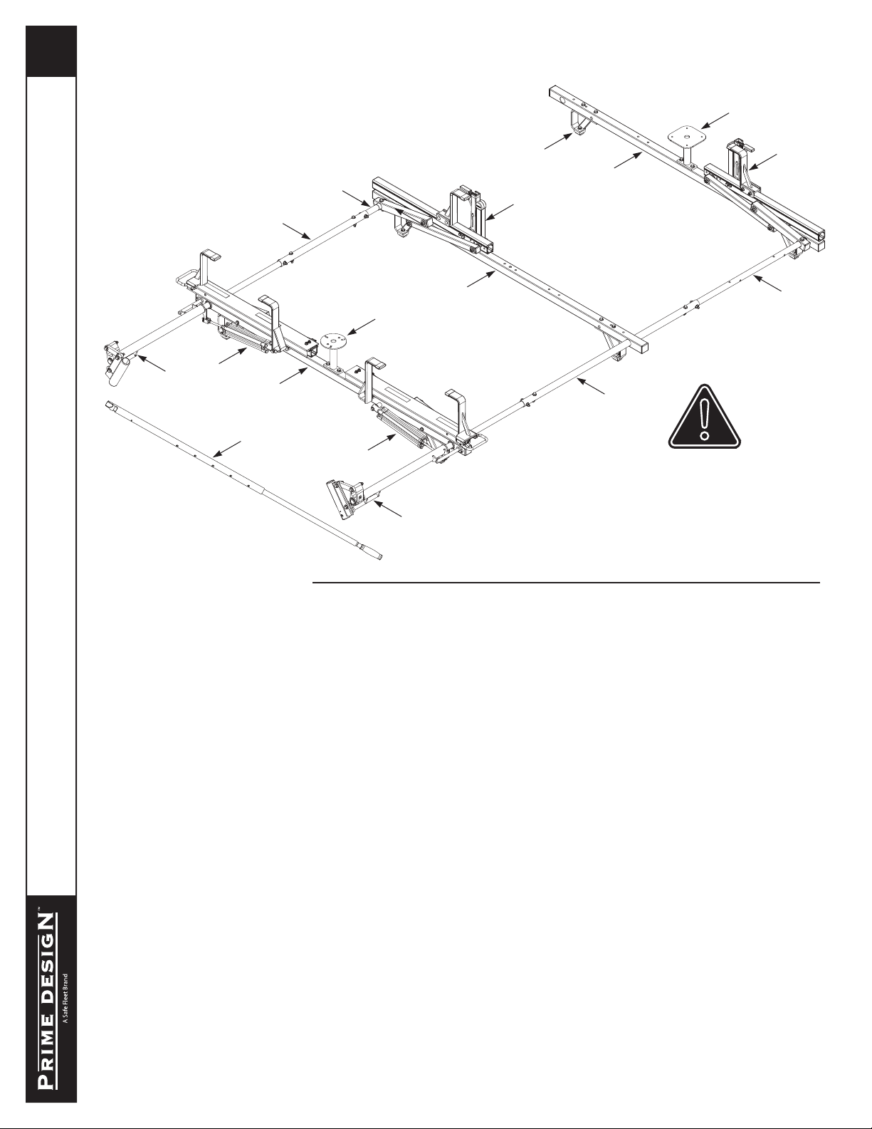
HRR-369-E-CM1 FULLY ASSEMBLED LADDER RACK ILLUSTRATION
TABLE OF CONTENTS
Page 2–6................................................................................................................................................... Packaging Checklist
Page 8–10.................................................................................................................................Mounting Bracket Assemblies
Page 11 ..................................................................................................................................Right Hand Rotation Illustration
Page 12–13 .......................................................................Right Rear Rotation Assembly-Crossbar and Drive Arm Bushing
Page 14–16 .......................................................................................................... Right Rear Rotation Assembly-Drive Shaft
Page 17.................................................................................................................... Right Rotation Assembly-Connecting Bar
Page 18 .............................................................................Right Front Rotation Assembly-Crossbar and Drive Arm Bushing
Page 19–20 ......................................................................................................... Right Front Rotation Assembly-Drive Shaft
Page 21 ................................................................................................................................Final Connecting Bar Adjustment
Page 22–23 ..................................................................Right Rear Rotation Assembly-Cylinder Assembly Rear Installation
Page 24 ...................................................................................................................................... Left Hand Rotation Assembly
Page 25 ................................................................................Left Rear Rotation Assembly-Crossbar and Drive Arm Bushing
Page 26–28 ............................................................................................................ Left Rear Rotation Assembly-Drive Shaft
Page 29 ..................................................................................................................... Left Rotation Assembly-Connecting Bar
Page 30 ...............................................................................Left Front Rotation Assembly-Crossbar and Drive Arm Bushing
Page 31–32 ............................................................................................................Left Front Rotation Assembly-Drive Shaft
Page 33 .......................................................................................................... Left Final Assembly-Connecting Bar Assembly
Page 34–35 .................................................................... Left Rear Rotation Assembly-Cylinder Assembly Rear Installation
Page 36–37 ............................................................................................................Front Right L Post and Z Post Installation
Page 38–39 ..............................................................................................................Front Left L Post and Z Post Installation
Page 40–41.......................................................................................... Front and Rear Accessory Strobe Holder Installation
Page 42 ............................................................................................................................ Final Assembly-Drive Shaft Sealing
Page 43 ............................................................................................... Final Assembly-Cylinder and Auto Clamp Adjustment
NOTE: Assemblies and parts shown in this
manual are representative. Some items
may appear differently than actual parts,
assemblies, or components received.


