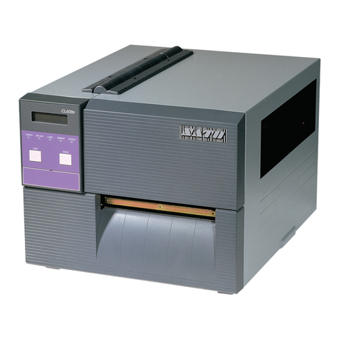
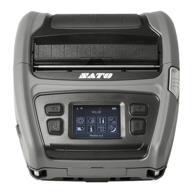
SATO CL6NX User manual

BARCODE PRINTER
CL6NX +Dispenser
(KITTING MANUAL)
APPROVED CHECKED INCHARGE
間下
2015.1.15
白濱
2015.1.15
横山
2015.1.15
15/Jan/2015
Production Engineer Dept
SATO TECHNOLOGY CO.,LTD
PE-E70Z02
原本
WWCL95200: Dispenser kit
WWCL95300: Dispenser kit + Rewind

Rev Date E.O
No. Description Revised Page(s) APR CHK PIC
- 15/Jan/2015 - 初版発行 - - - -
Revision History Model : DISPENSER / DISPENSER + REWIND Kitting (CL6NX)

CL6NX KITTING MANUAL Page. 1
For EXT PCB Assy
D3 REWIND ASSY
D7 DISPENSE ASSY
D4 REWIND CORE
SUB
For RELAY PCB Assy
10 R285180xx
EXT PCB ASSY 1
9 R291150xx
RELAY PCB ASSY 1
12 R288240xx
EXT SIGNAL
CABLE SET 1
S8 MD4300622
PAN SCREW SW+WL
(2JP3006 SW+WL) 4
S7 MD3300622
PAN SCREW SW+WS
(2JP3006 SW+WS) 2
9 P562409xx
MOTOR
COVER(DIS) 1
For Dispense Assy
For Dispense Bar
& DIS Front cover
7 P562405xx
DIS. PLATE 1
For Rewind Assy
8 R322189xx
BASE COVER
SET (DIS) 1
S3 MD4300622
PAN SCREW SW+WL
(2JP3006 SW+WL) 2
2 P554290xx
REWIND SP 1
S4 MD3401028 (Black)
PAN SCREW SW+WS
(8JP4010 SW+WS) 2
For DIS Front cover
S5 MD4300828 (Black)
PAN SCREW SW+WL
(8JP3008 SW+WL) 4
S2 MD4400822
PAN SCREW SW+WL
(2JP4008 SW+WL) 4
For Motor Cover(DIS)
S6 MD4400822
PAN SCREW SW+WL
(2JP4008 SW+WL) 2
13 JG100011A
TIE WRAP 1
DS KIT +RWMODEL only
3 ND0060030
E-SNAP RING
(E-6SU) 1
P047260xx
OILES BEARING
(80B-0810)
1 1
11 P321972xx
EXT POWER
CABLE SET 1

CL6NX KITTING MANUAL Page. 2
For RELAY PCB Assy
9 R291150xx
RELAY PCB ASSY 1
S7 MD3300622
PAN SCREW SW+WS
(2JP3006 SW+WS) 2
D7 DISPENSE ASSY
For Dispense Assy
For Dispense Bar
& DIS Front cover
7 P562405xx
DIS. PLATE 1
8 R322189xx
BASE COVER
SET (DIS) 1
S3 MD4300622
PAN SCREW SW+WL
(2JP3006 SW+WL) 2
S4 MD3401028 (Black)
PAN SCREW SW+WS
(8JP4010 SW+WS) 2
For DIS Front cover
S5 MD4300828 (Black)
PAN SCREW SW+WL
(8JP3008 SW+WL) 4
DS KIT MODEL only

CL6NX KITTING MANUAL
<Preparation tool and Caution>
*Phillips screwdriver +No.2
*Nipper
Please turn OFF the power before assembling the dispenser.
<Procedure (Dismantle)>
1. Open the open-cover, and Head-open
2. Remove (1) screw, and take-out (2) and (3) .
3. Remove (4) screw, and take-out (5) Cover-LH.
(3) FRONT COVER
BOTTOM (LH)
(2) FRONT COVER
BOTTOM
(1) PAN SCREW SW+WL
(MD3401428): 2pcs
Reuse
Disuse
Slide
Disuse
(4) PAN. SCREW SW+WL
(MD4401022)
(5) COVER LH
Reuse
Slide
& Lift up
Reuse
Notes> When remove the cover LH,
Please be careful that the cover does not touch the PCB
↑Deformed Capacitor by contact with the cover
Page. 3
DS KIT +RWMODEL
DS KIT MODEL

CL6NX KITTING MANUAL
5. Remove (6) screw, take out (7).
6. Remove (8) screw, take out (9).
7. Delete (modify) the circle shape of (9)
Use the nipper, please cut the ribs (3-places) of joint.
Modify method
of Label-hold-guide-RH
Delete
After
modification
Joint
Nipper
Notes>Without burr on the cut surface of the LABEL HOLDER
GUIDE -RH
Page. 4
Disuse
(7) DIS BLIND
COVER(RW)
Disuse
(6) PAN SCREW SW+WL
(MD4401022): 2pcs
(8) BIND P-TIGHT SCREW
(MH2300822): 3pcs
Reuse
Slide
(9) LABEL HOLDER
GUIDE -RH
Reuse (Need modify)
DS KIT +RWMODEL only

CL6NX KITTING MANUAL
<Procedure (Assembly)>
8. Attach (10), fix by (11) screw.
9. Attach (12), fix the motor cable.
10. Re-attach (13), fix by (14) screw.
Page. 5
Slide
(13) LABEL HOLDER
GUIDE -RH
(14) BIND P-TIGHT SCREW
(MH2300822): 3pcs
Reuse (modified parts)
Reuse
Torque : 3.5~4.5 Kg・cm
(10) REWIND MOTOR
SUB
KIT items
(11) PAN SCREW SW+WL
(MD4400822): 4pcs
KIT items
Torque : 14.0~16.0 Kg・cm
(12) TIE WRAP
(JG100011A):1pcs
KIT items
Motor cable is in the
shaded area ,do not
overlap
Screwing 4 places
Motor cable , fixed with
TIE WRAP.
Motor cable is in the
shaded area , do not
overlap
Motor cable
Tie wrap Motor cable
Insert the motor cable
Into the hole.
DS KIT +RWMODEL only

CL6NX KITTING MANUAL
11. Pass thru (15), (16), to Rewind-shaft
, and fix by Rewind-lock-plate.
12. Insert a (17) to Rewind core assy.
13. Attach (18) to the Rewind shaft.
14. Attach (19), fix by (20) screw.
15. Attach (22), and fix by (23) screw.
16. Connect the cable (24) and (25) and Dis-motor-cable
to power-supply and EXT-PCB
(16) REWIND CORE
ASSY
(24) DIS-POWER
CABLE (25) DIS-SIGNAL
CABLE
KIT items
KIT items
Page. 6
DIS-POWER CABLE
DIS-SIGNAL CABLE
POWER SUPPLY
( KB cable)
DIS-POWER CABLE DIS-MOTOR CABLE
EXT-PCB
KIT items
(19) EXT PCB
(20) PAN SCREW SW+WL
(MD4300622): 4pcs
KIT items
Torque : 7.0~8.0 Kg・cm
(22) MOTOR
COVER(DIS)
KIT items
KIT items
Torque : 14.0~16.0 Kg・cm
PAN SCREW SW+WL
(MD4400822): 2pcs
(23)
DS KIT +RWMODEL only
KIT items
KIT items
KIT items
OILES BEARING
(80B-0810) 1
(17)
E-SNAP RING
(E-6SU) 1
(18)
OILES BEARING
Fully inserted
The tip of the Rewind-shaft
,and mounting the E-snap ring.
E-snap ring
Fit the shape
(15) SPRING
KIT items
CL6NX KITTING MANUAL
15. Connect the (0) Option-cable on (26) Relay-PCB
* Option-cable is printer-side items.
16. Connect Dispense-unit’s cable (Dispense Sensor-
cable to Relay-PCB
17. Attach (26), fix by (27) screw.
18. Attach (28)
19. Attach (29), fix by (30) screw.
(0) OPTION CABLE
Dispense Sensor cable
(from Dispense Unit)
(28) FROTN COVER
UNDER (LH)
(29) DISPENSE UNIT
Reuse
(30) PAN SCREW SW+WS
(MD4300828): 4pcs
KIT items
KIT items
(26) RELAY-PCB KIT items
(27) PAN SCREW SW+WS
(MD3300622): 2pcs
KIT items
Torque : 3.5~4.5 Kg・cm
Torque : 7.0~8.0 Kg・cm
Page. 7
DS KIT +RWMODEL
DS KIT MODEL

CL6NX KITTING MANUAL
Slide
20. Open the Dispenser-unit.
21. Attach (31), fix by (32) screw.
<Note> Refer to below photo.
Set to match Center-line of Dispense-bar
and ▲mark (of Engine-frame), then fix it by screw.
22. Attach (33), fix by (34) and (35) screw
<Note>A convex protrusion , and placed in a
Front cover under(DS) holes.
23. Close the Dispenser-unit.
24. Attach (36), fix by (37).
Fin (Conversion)
Center line
(31) DISPENSER BAR
(34) PAN SCREW SW+WL
(MD3401028): 2pcs
Open
(35) PAN SCREW SW+WL
(MD4300622): 1pc
(33) FRONT COVER
UNDER (DS)
(32) PAN SCREW SW+WL
(MD4300622): 1pc
KIT items
KIT items
KIT items
KIT items
KIT items

Torque : 14.0~16.0 Kg・cm Torque : 7.0~8.0 Kg・cm
Torque : 7.0~8.0 Kg・cm
(37) PAN. SCREW SW+WL
(MD4401022)
(36) COVER LH
Reuse
Reuse
Torque : 14.0~16.0 Kg・cm
Page. 8
Convex put in the hole
Note
DS KIT +RWMODEL
DS KIT MODEL

CL6NX KITTING MANUAL
Label Route
<Check and adjust after assembly Dispenser-kit>
<Preparation (set the Label, etc)>
(1) Set Pressure roller in center of used label.
(2) Set Label and Ribbon to Printer
Label: Peel off the label (about 50cm) from Label roll
(3) Open the thermal-head
(4) Open the Dispense-unit, pass thru the Label into it.
<Method of mounting the label and ribbon>:see below
Page. 9
①Close the thermal-head
②③ Close the Dispense-unit while pulling
backing-paper
④Confirm that it does not loosen the
backing-paper.
If it has loosen (NG), perform ②③ again.
NG
OK
platen
Thermal
head
Dispense
bar
Pressure
roller
Set Label to Dispenser unit
①
③POINT
②
④
DS KIT MODEL only
Set method of Pressure roller
Pressure-roller
SLIDE
Head pressure adjustment, please refer to
the Operation Manual.

CL6NX KITTING MANUAL
①Pull the Rewind-lever
②Set backing-paper
③Push lever until inner-most
Set method of Label to Dispenser unit
④Close the head
⑤⑥ While winding (pulling) backing-paper
lightly, close the Dispense-unit
<Note>
Confirm that it does not loosen the backing-
paper on Dispense-bar
If it has loosen (NG), perform ⑤⑥ again.
Set method of backing-paper to Rewind-core
①
②③
Rewind-lever
④
⑤
⑥
OK
NG (loosen)
platen
Thermal-head
Dispense-bar
Pressure- roller
Label Route
<Check and adjust after assembly Dispenser-kit>
<Preparation (set the Label, etc)>
(1) Set Pressure roller in center of used label.
(2) Set Label and Ribbon to Printer
Label: Peel off the label (about 30cm) from Label roll
(3) Open the thermal-head
(4) Open the Dispense-unit, pass thru the Label into it.
(5) Clip the edge of backing paper by Rewind-core-lever.
*Winding direction is CCW:refer to below procedure
(6) Close the thermal-head
(7) While winding the Rewind-core (pull backing-paper),
close the Dispense-unit
Set method of Pressure roller
Pressure-roller
SLIDE
Page. 10
DS KIT +RWMODEL only
Head pressure adjustment, please refer to
the Operation Manual.

CL6NX KITTING MANUAL
<Check and adjust after assembly Dispenser-kit>
<Test printing method>
(1) Power ON the CL6NX printer (press 「Power」key)
(2) Clock display confirmation. (DS+RW MODEL only)
(3) Press 「Soft-L」
(4) Press 「Soft-R」,display the “Offline”
(5) Press 「Enter」key, display the “Settings”
(6) Press 「or 」key several times
Change Settings-menu; “Printing” “Tools”
(7) After select “Tools”, press 「Enter」key x 3-times
(8) After display “Factory”, press 「Soft-R」key.
Printer will be start printing the Factory-test-print.
When you want to stop printing, press 「Soft-R」key again.
Power
Soft-R
//
Soft-L
Back
Enter
Navigation
Page. 11
DS KIT +RWMODEL
DS KIT MODEL
20:30
Clock display
confirmation
DS KIT+RW MODEL only
To suit the user label (user ribbon),
please set the print darkness.

CL6NX KITTING MANUAL
<Check and adjust after assembly Dispenser-kit>
<Check contents and adjust>
Ⅰ. Dispense-Sensor function
Confirm that the next-label is printed when peeling-off the label.
(next-label does not printed before peeling-off the label)
Ⅱ. Dispense functions
(1) Confirm the label condition of after peeling-off
If it is a/b (NG) case, please adjust “Offset”
(a) Label is not retained on Dispense-bar (b) It doesn’t take peeling the label easily
NG
Backing-paper
Label OK
NG
2~4mm (Reference)
Power
Soft-R
//
Soft-L
Back
Enter
Navigation
<Adjust method of “Offset”>
(1) Set “Offset” value
In case of (a); Offset value Reduce ( )
(b); Increase ( )
(2) After setting,
By press 「Soft-R」key, printer is issued Test-printing.
When Label-pitch is less than 100mm,
Press 「」x3 times, press the [Soft-R] key.
Confirm the label-stop position is OK or NG.
If it was NG, please perform (1)~(2) again.
Then
If printing-position needs to adjust,
please set it by “Pitch” value.
//
Test-print
Label stop
position adjust
Printing position
adjust
Page.12
DS KIT +RWMODEL
DS KIT MODEL

CL6NX KITTING MANUAL
<Check and adjust after assembly Dispenser-kit>
Ⅱ. Dispense functions
(2) In case of printing (alignment) is slanting, or backing-paper is slant loading by rewind-core.
Adjust the slope angle of Dispense-bar
Adjust method
(1) Loose the screw
(2) After adjust, fix screw
Center line
Page.13
DS KIT +RWMODEL
DS KIT MODEL

CL6NX KITTING MANUAL
Modify the Cushion (Bottom-Front)
+DS & DS+REWIND model
Remove the Cushion piece
from Cushion (Bottom-Front)
•This small piece is not use
for +DS & DS+REWIND model,
please throw away it.
<Packing method>
1. Remove Small-piece from Cushion (Bottom-Front) ~with Dispenser &Dispenser +Rewind model
(1) CUSHION
(BOTTOM-FRONT )
Cushion (Bottom-Rear)
Cushion (Top Front -R)
Cushion (Top Front -L)
Cushion (Top Rear)
DS KIT +RWMODEL
DS KIT MODEL
Page.14

CL6NX KITTING MANUAL
PRINTER
FRONT SIDE
Cushion (B-F)
MODIFIED Cushion (B-R)
SLIT hole
Carton
spacer(FR)
Susunan packing item seperti gambarajah di bawah. Pastikan taping bawah
carton case bentuk “H”.
2 Q046428xx
CARTON
SPACER(FR) 1 5 Q046292xx
CUSHION (B-R) 1
7 Q046289xx
CUSHION (T-F- LH) 1
6 Q046288xx
CUSHION (T-F- RH) 1
8 Q046290xx
CUSHION (T-R) 1 9 Q046294xx
CARTON SPACER 1
1 Q046287xx
CARTON CASE
(PRINT) 1
PRINTER
FRONT SIDE
PRINTER
REAR SIDE
SLIT
3 Q046291xx
CUSHION (B-F) 1
Cushion (T-R)
Cushion (T-F-RH)
Cushion (T-F-LH) Carton Spacer
(tape tidak kelihatan)
PRINTER
front side
DS KIT +RWMODEL
DS KIT MODEL
TOP : H PASTE
BOTTOM : H PASTE
PACKING TAPE
Page.15
PRINTER FRONT SIDE
Direction
Parts No
0505
Parts No
This manual suits for next models
2
Table of contents
Other SATO Barcode Reader manuals

SATO
SATO MB400I User manual

SATO
SATO ARGOX AS-9400DC User manual

SATO
SATO PV4 User manual

SATO
SATO Argox OS-2130D User manual

SATO
SATO PV3 User manual

SATO
SATO ARGOX AS-9400DC User manual

SATO
SATO ARGOX AS-9400 User manual

SATO
SATO Argox P4 Series User manual

SATO
SATO ARGOX AS-9400DC User manual

SATO
SATO TC408 User manual
Popular Barcode Reader manuals by other brands

Datalogic
Datalogic QuickScan L QD 2300 Quick reference guide

Symbol
Symbol MicroKiosk MK1000 Product reference guide

Intermec
Intermec ScanPlus 1800 Getting started guide

Harbor Freight Tools
Harbor Freight Tools ZR8S OBD2 owner's manual

Custom Audio Electronics
Custom Audio Electronics SR500NM user manual

SICK
SICK CLV620 operating instructions