manuals.online logo
Brands
  1. Home
  2. •
  3. Brands
  4. •
  5. Sauder
  6. •
  7. Indoor Furnishing
  8. •
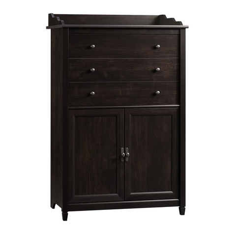
  9. Sauder 408726 User manual

Sauder 408726 User manual

Need help? Visit Sauder.com to view video assembly tips or chat with a live rep.
Prefer the phone? Call 1-800-523-3987.
Share your journey!
sauder.com
For all your
newfangled gadgetry.
NOTE: THIS INSTRUCTION
BOOKLET CONTAINS IMPORTANT
SAFETY INFORMATION.
PLEASE READ AND KEEP FOR
FUTURE REFERENCE.
English pg 1-18
Français pg 19-21
Español pg 22-24
Lot # 372058 05/06/15
Purchased: __________________
Be sure to give us a ring before
making any returns. 1-800-523-3987
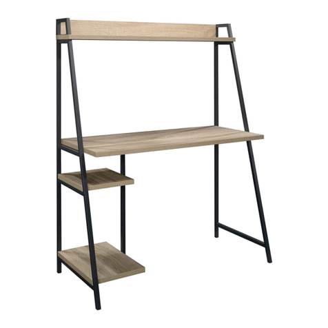
Computer Desk
Beginnnings Collection |Model 408726
Table of Contents Assembly Tools Required
Part Identification
Hardware Identification
Assembly Steps
Français
Español
Safety
Warranty
Hammer
Not actual size
No. 2 Phillips Screwdriver
Tip Shown Actual Size
Skip the power trip.
This time.
3
4
5-18
19-21
22-24
25-26
27
408726 www.sauder.com/servicesPage 2
Part Identification
åWhile not all parts are labeled, some of the parts will have a label or an inked letter on the edge
to help distinguish similar parts from each other. Use this part identification to help identify similar parts.
Now you know
our ABCs.
A2 RIGHT END (1)
B LEFT END (1)
C LOWER RIGHT END (1)
D3 UPRIGHT (1)
E3 SMALL UPRIGHT (1)
F2 TOP (1)
G3 DESK TOP (1)
HH3 SHELF (1)
I BOTTOM (1)
J BACK (1)
K2 SMALL BACK (1)
L MODESTY PANEL (1)
M KEYBOARD SHELF (1)
N DOOR (1)
408726www.sauder.com/services Page 3
A2
B
C
D3
E3
F2
G3
I
J
K2
L
M
N
HH3
Hardware Identification
åScrews are shown actual size. You may receive extra hardware with your unit.
408726 www.sauder.com/servicesPage 4
BLACK 1-1/8" PAN HEAD SCREW - 1
KK
BLACK 7/8" FLAT HEAD SCREW - 2
FF
WASHER - 1
Y
PIVOT HINGE- 2
X
BROWN 7/16" LARGE HEAD SCREW - 2
HH
BLACK 1-7/8" FLAT HEAD SCREW - 8
DD
CAM COVER - 7
BB
CORD CLIP - 1
AA
EE BROWN 1" FLAT HEAD SCREW - 4
SCREW COVER - 11
CC
II GOLD 5/16" FLAT HEAD SCREW - 4
HANDLE -1
Z
MAGNETIC CATCH- 1
V2
BLACK 1/2" FLAT HEAD SCREW - 1
GG
STRIKE PLATE - 1
W
NAIL - 12
JJ
HIDDEN CAM - 10
S2 CAM DOWEL - 10
T2
BLACK 1-15/16" FLAT HEAD SCREW - 7
113S
30AD DRAWER LEFT - 1
30AA CABINET RIGHT - 1 30AC DRAWER RIGHT - 1
30AB CABINET LEFT - 1
Step 1 Look for this icon. It means a
video assembly tip is available at
www.sauder.com/services/tips
å Assemble your unit on a carpeted floor or on the empty
carton to avoid scratching your unit or the floor.
å Push ten HIDDEN CAMS (S2) into the ENDS (A2, B, and C),
UPRIGHT (D3), SMALL UPRIGHT (E3), and SMALL BACK (K2).
Then, insert the metal end of the CAM DOWEL (T2) into each
HIDDEN CAM.
408726www.sauder.com/services Page 5
A2
B
C
D3
E3
K2
Arrow
S2
T2
Do not tighten the HIDDEN CAMS in this step.
Insert the metal end of the CAM
DOWEL into the HIDDEN CAM.
Arrow
Scan this QR code or go to this address:
http://qr.sauder.com/?ID=1093
to watch a video on how to assemble your unit.
å Fasten the CABINET RIGHT (30AA) and CABINET LET (30AB)
to the LEFT END (B) and UPRIGHT (D3). Use four GOLD 5/16"
FLAT HEAD SCREWS (II).
Step 2
408726 www.sauder.com/servicesPage 6
Roller end
Roller end
GOLD 5/16" FLAT HEAD SCREW
(4 used in this step)
II
B
D3
Finished edge
Finished edge
Remember:
Righty tighty.
Lefty loosey.
å Fasten the SMALL UPRIGHT (E3) to the SMALL BACK (K2).
Use a BLACK 1-15/16" FLAT HEAD SCREW (113S).
Step 3
408726www.sauder.com/services Page 7
E3
K2
BLACK 1-15/16" FLAT HEAD SCREW
(1 used in this step)
113S
Finished edge
Finished edge
Surface without
HIDDEN CAM
Surface with
HIDDEN CAM
å Fasten the SMALL UPRIGHT (E3) and SMALL BACK (K2)
to the TOP (F2). Tighten two HIDDEN CAMS.
Step 4
408726 www.sauder.com/servicesPage 8
Surface with
HIDDEN CAM
E3
K2
F2
Start Tighten
Arrow
Minimum
190 degrees
Caution
Risk of damage or
injury. HIDDEN CAMS
must be completely
tightened. HIDDEN
CAMS that are not
completely tightened
may loosen, and parts
may separate. To
completely tighten:
Arrow
Maximum
210 degrees
å Fasten the DESK TOP (G3) to the SMALL UPRIGHT (E3)
and SMALL BACK (K2). Use two BLACK 1-15/16" FLAT
HEAD SCREWS (113S).
Step 5
408726www.sauder.com/services Page 9
E3
K2
BLACK 1-15/16" FLAT HEAD SCREW
(2 used in this step)
113S
Long finished edge
Unfinished surface
G3
For support, place packing
foam and magazines here.
å Carefully turn your unit onto its front edges.
å Fasten the LEFT END (B) and UPRIGHT (D3) to the DESK
TOP (G3). Tighten four HIDDEN CAMS.
Step 6
408726 www.sauder.com/servicesPage 10
B
D3
G3
Unfinished edge
Unfinished edge
Arrow
Minimum
190 degrees
Maximum
210 degrees
å Fasten the MODESTY PANEL (L) to the LEFT END (B)
and UPRIGHT (D3). Use four BLACK 1-7/8" FLAT HEAD
SCREWS (DD).
Step 7
408726www.sauder.com/services Page 11
B
D3
L
Unfinished surface
Notch
BLACK 1-7/8" FLAT HEAD SCREW
(4 used in this step)
DD
DD
å Fasten the RIGHT END (A2) to the TOP (F2). Tighten two
HIDDEN CAMS.
å Fasten the SHELF (HH3) to the RIGHT END (A2) and
UPRIGHT (D3). Use four BLACK 1-15/16" FLAT HEAD
SCREWS (113S).
å Fasten a MAGNETIC CATCH (V2) to the SHELF (HH3).
Use a BLACK 1-1/8" PAN HEAD SCREW (KK).
Step 8
408726 www.sauder.com/servicesPage 12
Arrow
Minimum
190 degrees
Maximum
210 degrees
Unfinished
surface
A2
D3
F2
HH3
Unfinished edge
BLACK 1-15/16" FLAT HEAD SCREW
(4 used in this step)
113S
BLACK 1-1/8" PAN HEAD SCREW
(1 used in this step)
KK
V2
å Fasten the LOWER RIGHT END (C) to the SHELF (HH3).
Tighten two HIDDEN CAMS.
å Fasten the BOTTOM (I) to LOWER RIGHT END (C) and
UPRIGHT (D3). Use four BLACK 1-7/8" FLAT HEAD
SCREWS (DD).
Step 9
408726www.sauder.com/services Page 13
D3
HH3
CI
BLACK 1-7/8" FLAT HEAD SCREW
(4 used in this step)
DD
Unfinished edge
Arrow
Minimum
190 degrees
Maximum
210 degrees
å Make equal margins along all four edges of the BACK (J). Push
on opposite corners of your unit if needed to make it “square”.
å Fasten the BACK (J) to your unit using the NAILS (JJ).
Step 10
408726 www.sauder.com/servicesPage 14
J
Do not stand the unit upright without the
BACK fastened. The unit may collapse.
Caution
NAIL
(12 used in this step)
JJ
å Fasten a PIVOT HINGE (X) to the DOOR (N). Use one
BROWN 7/16" LARGE HEAD SCREW (HH).
å Fasten a STRIKE PLATE (W) to the DOOR (N). Use one
BLACK 1/2" FLAT HEAD SCREW (GG).
å NOTE: The surface of the STRIKE PLATE with “SAUDER”
should be facing up.
Step 11
408726www.sauder.com/services Page 15
BLACK 1/2" FLAT HEAD SCREW
(1 used in this step)
GG
BROWN 7/16" LARGE HEAD SCREW
(1 used for the PIVOT HINGE)
HH
N
W
X
IMPORTANT: ONLY fasten one HINGE to the DOOR in this step.
Now might be a
good time to refresh
your drink.
å Carefully stand your unit upright.
å 1. Insert the remaining PIVOT HINGE (X) into the
WASHER (Y) and into the BOTTOM(I).
å 2. Insert the PIVOT HINGE, which is fastened to the
DOOR (N), into the hole in the SHELF (HH3). You will
need to tilt your DOOR slightly.
å 3. Now, tip the DOOR in and fasten the free HINGE to the
DOOR. Use a BROWN 7/16" LARGE HEAD SCREW (HH)
å Fasten the HANDLE (Z) to the DOOR (N). Use two BLACK
7/8" FLAT HEAD SCREWS (FF).
å NOTE: To make adjustments to the DOOR, loosen the
SCREW in the HINGE, make needed adjustments, and
tighten the SCREW.
Step 12
408726 www.sauder.com/servicesPage 16
31S
BLACK 7/8" FLAT HEAD SCREW
(2 used for the HANDLE)
FF
BROWN 7/16" LARGE HEAD SCREW
(1 used for the PIVOT HINGE)
HH
X
Y
N
I
HH3
Z
1st
2nd
3rd
å Fasten the DRAWER RIGHT (30AC) and DRAWER LEFT (30AD)
to the KEYBOARD SHELF (M). Use four BROWN 1" FLAT
HEAD SCREWS (EE).
å Turn the CORD CLIP (AA) into the KEYBOARD SHELF (M).
å NOTE: The CORD CLIP is used to hold your keyboard
cord against the KEYBOARD SHELF.
Step 13
408726www.sauder.com/services Page 17
AA
BROWN 1" FLAT HEAD SCREW
(4 used in this step)
EE
Finished surface
Roller end
Roller end
M
Almost time to
celebrate! With a nap.
å To insert the KEYBOARD SHELF (M) into your unit, tip the
front of the shelf down and drop the rollers on the shelf
behind the rollers on the unit. Lift the front of the shelf up
and slide it into the unit.
å Push a CAM COVER (BB) onto each HIDDEN CAM.
å Cover the visible SCREWS with a SCREW COVER (CC). Center
a COVER over the head of each SCREW and press firmly.
å NOTE: Please read the back pages of the instruction
booklet for important safety information.
å This completes assembly. Clean with your favorite
furniture polish or a damp cloth. Wipe dry.
Step 14
408726 www.sauder.com/servicesPage 18
M
BB
CC
(11 used)
(7used)
To cover HIDDEN CAMS
To cover screws
15 lbs.
20 lbs.
25 lbs.
30 lbs.
50 lbs.
And to celebrate, why not share your success story?
A l’usage exclusif du
Canada Noter la date
d’achat de cet élément
et conserver le livret
pour future référence.
Pour contacter Sauder
en ce qui concerne cet
élément, faire référence
au numéro de lot et
numéro de modèle en
appelant notre numéro
sans frais.
Lot nº : ____________
Date de
l’achat: ____________
LISTE DE PIÈCES
REFERENCE DESCRIPTION QUANTITÉ
LISTE DE PIÈCES
REFERENCE DESCRIPTION QUANTITÉ
NOUS SOMMES LA POUR VOUS AIDER!
Nous faisons de notre mieux pour nous assurer que votre meuble
arrive dans d’excellentes conditions. Nos représentants du service
Clientèle sont aimables et prêts à vous aider au cas où une pièce
aurait été endommagée ou manquerait (ou si vous aviez besoin
d’aide pour l’assemblage). NE RAMENEZ PAS LE MEUBLE AU
MAGASIN. Au Canada, composez ce numéro d’appel gratuit:
1-800-523-3987
Du lundi au vendredi, de 9 heures du matin à
5:30 heures du soir (horaire Côte Est)
(sauf jours fériés)
Si une pièce a besoin d’être remplacée, la pièce de remplacement
sera envoyée dans les 48 heures. (Sauf week-ends et jours fériés)
Utilisez les instructions d’assemblage en français avec les
schémas étape par étape du manuel d’instruction en anglais.
Chaque étape en français correspond à la même étape
en anglais. La pièce devant être attachée à l’élément est
représentée en gris sur les schémas de chaque étape pour plus
de précision. Comparer la “Liste de pièces” ci-dessous avec
la “PART IDENTIFICATION” du manuel en anglais pour vous
familiariser avec les pièces avant l’assemblage.
REMARQUE : CE MANUEL D’INSTRUCTIONS CONTIENT
D’IMPORTANTES INFORMATIONS RELATIVES À LA SÉCURITÉ.
À LIRE ET CONSERVER POUR TOUTE RÉFÉRENCE FUTURE.
Bureau d’Ordinateur
Z POIGNÉE.............................................................................1
AA CLIP DE CORDON.......................................................1
BB COUVERCLE D’EXCENTRIQUE.......................7
CC COUVERCLE DE VIS...............................................11
DD VIS NOIRE TÊTE PLATE 48 mm ...................8
EE VIS MARRON TÊTE
PLATE 25 mm...............................................................4
FF VIS NOIRE TÊTE PLATE 22 mm.....................2
GG VIS NOIRE TÊTE PLATE 13 mm.......................1
HH VIS MARRON TÊTE
LARGE 11 mm................................................................2
II VIS DORÉE TÊTE PLATE 8 mm .....................4
JJ CLOU ..................................................................................12
KK VIS NOIRE TÊTE GOUTTE DE
SUIF 28 mm.....................................................................1
113S VIS NOIRE TÊTE PLATE 49 mm.....................7
A2 EXTRÉMITÉ DROITE..................................................1
B EXTRÉMITÉ GAUCHE...............................................1
C EXTRÉMITÉ DROITE
INFÉRIEURE......................................................................1
D3 MONTANT..........................................................................1
E3 PETIT MONTANT.........................................................1
F2 DESSUS...............................................................................1
G3 DESSUS DE BUREAU...............................................1
HH3 TABLETTE..........................................................................1
I DESSOUS...........................................................................1
J ARRIÈRE ..............................................................................1
K2 PETIT ARRIÈRE..............................................................1
L VOILE DE FOND...........................................................1
M TABLETTE DE CLAVIER..........................................1
N PORTE...................................................................................1
30AA ÉLÉMENT DROITE.....................................................1
30AB ÉLÉMENT GAUCHE..................................................1
30AC TIROIR DROIT................................................................1
30AD TIROIR GAUCHE.........................................................1
S2 EXCENTRIQUE ESCAMOTABLE..................10
T2 CHEVILLE D’EXCENTRIQUE............................10
V2 LOQUETEAU MAGNÉTIQUE..............................1
W PLAQUE DE BUTÉE....................................................1
X CHARNIÈRE À PIVOT..............................................2
Y RONDELLE........................................................................1
408726www.sauder.com/services Page 19
Modèle 408726
ÉTAPE 9
Fixer l’EXTRÉMITÉ DROITE INFÉRIEURE (C) à la TABLETTE (HH3).
Serrer deux EXCENTRIQUES ESCAMOTABLES. Utiliser un TOURNEVIS
À POINTE DROITE.
Fixer le DESSOUS (I) à l’EXTRÉMITÉ DROITE INFÉRIEURE (C) et au
MONTANT (D3). Utiliser quatre VIS NOIRES TETE PLATE 48 mm (DD).
ÉTAPE 8
Fixer l’EXTRÉMITÉ DROITE (A2) au DESSUS (F2). Serrer deux
EXCENTRIQUES ESCAMOTABLES. Utiliser un TOURNEVIS À
POINTE DROITE.
Fixer la TABLETTE (HH3) à l’EXTRÉMITÉ DROITE (A2) et
MONTANT (D3). Utiliser quatre VIS NOIRES TETE
PLATE 49 mm (113S).
Enfoncer le LOQUETEAU MAGNÉTIQUE (V2) dans le trou de la
TABLETTE (HH3).
ÉTAPE 7
Fixer le VOILE DE FOND (L) à l’EXTRÉMITÉ GAUCHE (B)
et MONTANT (D3). Utiliser quatre VIS NOIRES TETE
PLATE 48 mm (DD).
ÉTAPE 6
Avec précaution, retourner l’élément sur ses chants avant.
Fixer l’EXTRÉMITÉ GAUCHE (B) et MONTANT (D3) au
DESSUS DE BUREAU (G3). Serrer quatre EXCENTRIQUES
ESCAMOTABLES.
ÉTAPE 4
Fixer le PETIT MONTANT (E3) auPETIT ARRIÈRE (K2) et
auDESSUS (F2). Serrer deux EXCENTRIQUES ESCAMOTABLES.
ÉTAPE 5
Fixer le DESSUS DE BUREAU (G3) au PETIT MONTANT (E3) et
au PETIT ARRIÈRE (K2). Utiliser deux VIS NOIRES TÊTE PLATE
49 mm (113S).
ÉTAPE 3
Fixer le PETIT MONTANT (E3) au PETIT ARRIÈRE (K2). Utiliser
une VIS NOIRE TÊTE LARGE 49 mm (113S).
ÉTAPE 2
Fixer l'ÉLÉMENT DROITE (30AA) et l'ÉLÉMENT GAUCHE (30AB)
à l’EXTRÉMITÉ GAUCHE (B) et au MONTANT (D3). Utiliser quatre
VIS DORÉES TÊTE PLATE 8 mm (II).
ÉTAPE 1
Assembler l’élément sur un sol à moquette ou sur le carton vide
pour éviter d’endommager l’élément ou le sol.
Enfoncer dix EXCENTRIQUES ESCAMOTABLES (S2) dans
les EXTRÉMITÉS (A2, B et C), le MONTANT (D3), le PETIT
MONTANT (E3) et le PETIT ARRIÈRE (K2). Ensuite, insérer une
CHEVILLE D’EXCENTRIQUE (T2) dans chaque EXCENTRIQUE
ESCAMOTABLE.
408726 www.sauder.com/servicesPage 20

Other manuals for 408726

2

Other Sauder Indoor Furnishing manuals

Sauder Harvest Mill 404962 User manual

Sauder

Sauder Harvest Mill 404962 User manual

Sauder 420612 User manual

Sauder

Sauder 420612 User manual

Sauder Jaclyn Smith Gatsby 415693 User manual

Sauder

Sauder Jaclyn Smith Gatsby 415693 User manual

Sauder 420011 User manual

Sauder

Sauder 420011 User manual

Sauder Cannery Bridge 426140 User manual

Sauder

Sauder Cannery Bridge 426140 User manual

Sauder HomePlus 422428 User manual

Sauder

Sauder HomePlus 422428 User manual

Sauder Shoal Creek 422191 User manual

Sauder

Sauder Shoal Creek 422191 User manual

Sauder Office Works Affirm 427450 User manual

Sauder

Sauder Office Works Affirm 427450 User manual

Sauder Soft Modern 414969 User manual

Sauder

Sauder Soft Modern 414969 User manual

Sauder Harbor View 420474 User manual

Sauder

Sauder Harbor View 420474 User manual

Sauder worksense MASON PEAK Credenza 427805 User manual

Sauder

Sauder worksense MASON PEAK Credenza 427805 User manual

Sauder Carson Forge 419575 User manual

Sauder

Sauder Carson Forge 419575 User manual

Sauder 419119 User manual

Sauder

Sauder 419119 User manual

Sauder 414443 User manual

Sauder

Sauder 414443 User manual

Sauder 414724 User manual

Sauder

Sauder 414724 User manual

Sauder Dakota Pass 418268 User manual

Sauder

Sauder Dakota Pass 418268 User manual

Sauder Canal Street 420494 User manual

Sauder

Sauder Canal Street 420494 User manual

Sauder Palladia Hutch 412308 User manual

Sauder

Sauder Palladia Hutch 412308 User manual

Sauder 422807 User manual

Sauder

Sauder 422807 User manual

Sauder Hudson 427873 User manual

Sauder

Sauder Hudson 427873 User manual

Sauder Cannery Bridge 429512 User manual

Sauder

Sauder Cannery Bridge 429512 User manual

Sauder 101785 User manual

Sauder

Sauder 101785 User manual

Sauder 402159 User manual

Sauder

Sauder 402159 User manual

Sauder 423109 User manual

Sauder

Sauder 423109 User manual

Popular Indoor Furnishing manuals by other brands

Cooper Lighting Lumark VL Specification sheet

Cooper Lighting

Cooper Lighting Lumark VL Specification sheet

Mocka Reese Assembly instructions

Mocka

Mocka Reese Assembly instructions

Lightolier Calculite C4CFL18 specification

Lightolier

Lightolier Calculite C4CFL18 specification

Furinno 12078 Assembly instruction

Furinno

Furinno 12078 Assembly instruction

Mocka Trestle Desk Assembly instructions

Mocka

Mocka Trestle Desk Assembly instructions

Argos 473/8639 Assembly instructions

Argos

Argos 473/8639 Assembly instructions

True 9212 operating instructions

True

True 9212 operating instructions

Greentouch Scott Living 1053VA-54-221 Assembly / care & use instructions

Greentouch

Greentouch Scott Living 1053VA-54-221 Assembly / care & use instructions

JR Home IF-DK225 Assembly instructions

JR Home

JR Home IF-DK225 Assembly instructions

Lifely Pebble Series Assembly instructions

Lifely

Lifely Pebble Series Assembly instructions

Living Spaces revive owner's manual

Living Spaces

Living Spaces revive owner's manual

Maintal Figaro EB SH52 OHNE Assembly instructions

Maintal

Maintal Figaro EB SH52 OHNE Assembly instructions

Southern Enterprises CM5071 Assembly instructions

Southern Enterprises

Southern Enterprises CM5071 Assembly instructions

Costway JV10615US-DK user manual

Costway

Costway JV10615US-DK user manual

Walker Edison BWTLD46 Assembly instructions

Walker Edison

Walker Edison BWTLD46 Assembly instructions

Zoovilla TOY0133710000 quick start guide

Zoovilla

Zoovilla TOY0133710000 quick start guide

Elle Decor Stara 6773809 Assembly instructions and warranty information

Elle Decor

Elle Decor Stara 6773809 Assembly instructions and warranty information

la vie vert P1 Assembly instruction

la vie vert

la vie vert P1 Assembly instruction

manuals.online logo
manuals.online logoBrands
  • About & Mission
  • Contact us
  • Privacy Policy
  • Terms and Conditions

Copyright 2025 Manuals.Online. All Rights Reserved.