manuals.online logo
Brands
  1. Home
  2. •
  3. Brands
  4. •
  5. Sauder
  6. •
  7. Indoor Furnishing
  8. •
  9. Sauder 433242 User manual

Sauder 433242 User manual

sauder.com
NOTE: THIS INSTRUCTION
BOOKLET CONTAINS IMPORTANT
SAFETY INFORMATION.
PLEASE READ AND KEEP FOR
FUTURE REFERENCE.
sauder.com
CONTACT US FIRST
BEFORE MAKING ANY RETURNS TO THE STORE.
sauder.com
CONTACT US FIRST
BEFORE MAKING ANY RETURNS TO THE RETAILER.
Visit sauder.com/service to order replacement parts, view video assembly tips, or chat with a live rep.
Prefer the phone? Give us a ring at 1-800-445-1527.
Customer Service is available Monday-Friday - 9 a.m. to 5:30 p.m. EST (except holidays)
Sauder.com
Share your journey!
English pg 1-18
Français pg 19-21
Español pg 22-24
Lot # 578195 02/18/22
Purchased: __________________
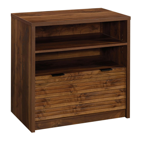
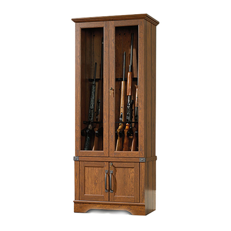
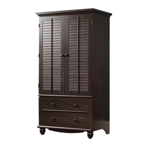
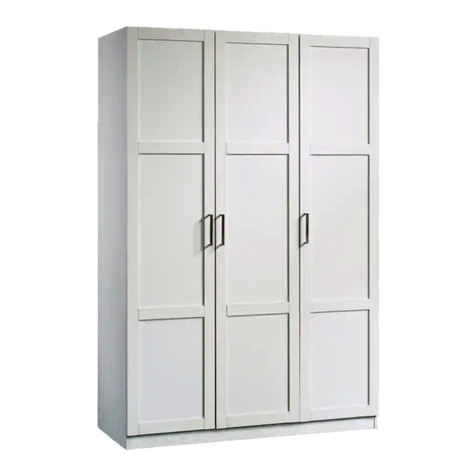
Storage Cabinet
Model 433242
Store behind
closed doors.
Part Identification
Hardware Identification
Hardware Usage Guide
Assembly Steps
Français
Español
Safety
Warranty
Table of Contents Assembly Tools Required
Hammer
Not actual size
No. 2 Phillips Screwdriver
Tip Shown Actual Size
3
4
5
6-18
19-21
22-24
25-26
27
Page 2 www.sauder.com/service 433242
Electric drill with 1/8" or 3/8" bit
(ONLY in indicated step)
Pencil
Part Identification
åWhile not all parts are labeled, some of the parts will have a label or an inked letter on the edge
to help distinguish similar parts from each other. Use this part identification to help identify similar parts.
Now you know
our ABCs.
A LEFT END (1)
B RIGHT END (1)
C TOP (1)
D BOTTOM (1)
E SHELF (1)
F ADJUSTABLE SHELF (2)
G LEFT DOOR (1)
H RIGHT DOOR (1)
J BACK (1)
Page 3www.sauder.com/service433242
A
B
C
D
E
F
G
H
J
F
Hardware Identification
åScrews are shown actual size. You may receive extra hardware with your unit.
Page 4 www.sauder.com/service 433242
HIDDEN CAM - 8
1CAM SCREW - 8
2WOOD DOWEL - 12
3PULL - 2
4
HINGE - 6
7
SHELF PIN - 8
5NAIL - 30
6
5/8" MACHINE SCREW - 4
11
2" FLAT HEAD SCREW - 4
10
1/2" FLAT HEAD SCREW - 12
12
APPLIQUE CARD - 1
8BUMPER CARD - 1
9FURNITURE TIPPING
RESTRAINT KIT - 1
96
Hardware Usage Guide
HOW TO USE A HIDDEN CAM & CAM SCREW OR CAM DOWEL
NOTE: Various CAM SCREWS or a CAM DOWEL may be used.
Cam Screws Cam Dowel
Turn the CAM SCREW or
gently tap the CAM DOWEL
until the shoulder is against
the surface of the part.
1.
3.
1
2
Insert the CAM SCREW or CAM DOWEL into the
HIDDEN CAM. Tighten the HIDDEN CAM.
Hidden Cam
Arrow
Push a HIDDEN CAM into
the part. The arrow in the
HIDDEN CAM must point
toward the hole in the
edge of the board.
Hole
2.
Page 5www.sauder.com/service433242
å Assemble your unit on a carpeted floor or on the
empty carton to avoid scratching your unit or the floor.
å Push eight HIDDEN CAMS (1) into the BOTTOM (D)
and SHELF (E).
å Turn four CAM SCREWS (2) into the LEFT END (A).
Look for this icon. It means a video assembly tip is
available at www.sauder.com/service/tips
Find the numbered video or scan the QR code.
Step 1
Page 6 www.sauder.com/service 433242
2
1
1
Arrow
1
Arrow
A
D
E
These holes
must be here.
å Insert four WOOD DOWELS (3) into the LEFT END (A).
å Fasten the BOTTOM (D) and SHELF (E) to the LEFT
END (A). Tighten four HIDDEN CAMS.
å NOTE: Be sure the WOOD DOWELS in the END insert
into the BOTTOM and SHELF.
Step 2
Page 7www.sauder.com/service433242
3
Do not stand the unit upright without the
BACK fastened. The unit may collapse.
Caution
1
A
E
Surface with
HIDDEN CAMS
These holes
must be here.
Unfinished edge
D
Surface with
HIDDEN CAMS
Unfinished edge
Step 3
Page 8 www.sauder.com/service 433242
å Turn four CAM SCREWS (2) into the RIGHT END (B).
å Insert four WOOD DOWELS (3) into the RIGHT END (B).
å Fasten the RIGHT END (B) to the BOTTOM (D) and
SHELF (E). Tighten four HIDDEN CAMS.
å NOTE: Be sure the WOOD DOWELS in the END insert
into the BOTTOM and SHELF.
3
1
2
3
B
E
DB
Just think. The sooner
you do this, the sooner
you do something else.
These holes
must be here.
å Open the FURNITURE TIPPING RESTRAINT KIT (96),
and fasten the SAFETY STRAP to the TOP (C). Use the
provided SHORT SCREW.
å Insert four WOOD DOWELS (3) into the TOP (C).
å Fasten the TOP (C) to the ENDS (A and B). Use four 2"
FLAT HEAD SCREWS (10).
å NOTE: You should start each SCREW a few turns before
completely tightening any of them.
Step 4
Page 9www.sauder.com/service433242
96
3
3
C
A
B
C
Use the SHORT SCREW
from the RESTRAINT KIT.
SAFETY STRAP
2" FLAT HEAD SCREW
(4 used in this step)
10
The SAFETY
STRAP should be
closer to this edge.
Surface with
more holes
Surface with fewer holes
Step 5
Page 10 www.sauder.com/service 433242
å Unfold the BACK (J) and lay it over your unit.
å Make equal margins along the top and bottom edges of
the BACK (J). Then, make equal margins along the side
edges of the BACK (J). Push on opposite corners of your
unit if needed to make it "square".
å Fasten the BACK (J) to your unit using the NAILS (6).
å NOTE: Be sure to tap NAILS into the holes that line up
over the SHELF (E).
Do not stand the unit upright without the
BACK fastened. The unit may collapse.
Caution
Unfinished
surface
These holes must line
up over the SHELF (E).
NAIL
(30 used in this step)
6
8
J
Step 6
Page 11www.sauder.com/service433242
1st
Electric drill with 1/8" bit
2nd
96
å Carefully stand your unit upright against the wall in its final location.
å NOTE: The following instructions show your unit being fastened to a wall stud. If you are not fastening your unit to a
wall stud, go to the next step now.
å 1st- Locate the center of a stud in your wall near your unit and mark it with a pencil.
å 2nd- Drill a 1/8" hole on the mark and into the stud in your wall.
å 3rd-
Fasten the unit to the wall. Use the LONG SCREW through the other end of the SAFETY STRAP and into the 1/8" hole.
3rd
Mark and drill
a 1/8" hole into
the wall stud.
Step 7
Page 12 www.sauder.com/service 433242
4th
96
1st
Electric drill with 3/8" bit
2nd
3rd
Mark and drill
a 3/8" hole
into the wall.
å 1st- With your pencil, strike a mark through the center of the hole in the SAFETY STRAP.
å 2nd- Drill a 3/8" hole on the mark.
å 3rd- While you squeeze the wings together, gently tap the WALL ANCHOR from the FURNITURE TIPPING
RESTRAINT KIT (96) into the hole until it is even with the surface of the wall.
å 4th- Turn the LONG SCREW through the hole in the SAFETY STRAP and into the WALL ANCHOR.
å NOTE: You will need to turn the LONG SCREW multiple turns to completely tighten and secure your unit to the wall.
å Insert the SHELF PINS (5) into the hole locations of your
choice in the ENDS (A and B). Set the ADJUSTABLE
SHELVES (F) onto the SHELF PINS.
Step 8
Page 13www.sauder.com/service433242
(8 used)
B
F
A
F
5
å Fasten the HINGES (7) to the DOORS (G and H). Use
twelve 1/2" FLAT HEAD SCREWS (12).
Step 9
Page 14 www.sauder.com/service 433242
7
H
G
7
1/2" FLAT HEAD SCREW
(12 used in this step)
12
17
Step 10
Page 15www.sauder.com/service433242
17
å Before fastening the DOOR to your unit, be sure the
mounting screw is against the stops as shown in the
right diagram. If it isn't, loosen the adjusting screw and
mounting screw to slide it against the stops. Then tighten
the mounting screw.
å Fasten the LEFT DOOR (G) to the LEFT END (A) as shown
in the lower diagram. Use the screws in the HINGES. You
should start each SCREW a few turns before completely
tightening any of them.
å Fasten one PULL (4) to the LEFT DOOR (G). Use two 5/8"
MACHINE SCREWS (11).
å Repeat this step for the RIGHT DOOR (H).
å See the next step for DOOR adjustments.
Mounting
screw
Stop
Hinge
Adjusting
screw
A
B
H
G4
4
5/8" MACHINE SCREW
(4 used for the PULLS)
11
Step 11
Page 16 www.sauder.com/service 433242
å Refer to the enlarged diagram to identify the parts on the HINGE.
å The DOOR may need some adjustments. Follow the text below
to make needed adjustments.
å DOOR ADJUSTMENTS:
To adjust the DOOR from side to side (horizontal), turn the
adjusting screw in or out.
å To adjust the DOOR up and down (vertical), loosen both vertical
adjustment screws. Move the DOOR up or down to the desired
location. Tighten the screws after making adjustments.
å To adjust the DOOR in or out (depth), loosen the mounting screw
one turn and move the DOOR in or out, as needed. Tighten the
mounting screw after making adjustments.
(vertical adjustment)
Adjusting screw (horizontal)
Mounting screw (depth)
17
å Peel APPLIQUES from the APPLIQUE CARD (8) and stick
them onto each PULL SCREW head in the DOORS (G and H).
å Peel BUMPERS from the BUMPER CARD (9) and stick them
onto the bottom corner of each DOOR (G and H) where the
DOOR comes into contact with the BOTTOM (D).
Step 12
Page 17www.sauder.com/service433242
Almost time to
celebrate! With a nap.
8
9
H
G
D
Step 13
Page 18 www.sauder.com/service 433242
å NOTE: Please read the back pages of the instruction booklet for important safety information.
å This completes assembly. Clean with a damp cloth. Wipe dry.
And to celebrate, why not share your success story at sauder.com or
25 lbs.
50 lbs.
No load
25 lbs.
25 lbs.
Noter la date d’achat
de cet élément et
conserver le livret pour
future référence. Pour
contacter Sauder en
ce qui concerne cet
élément, faire référence
au numéro de lot et
numéro de modèle en
appelant notre numéro
sans frais.
Lot nº : ____________
Date de
l'achet : ____________
LISTE DE PIÈCES
REFERENCE DESCRIPTION QUANTITÉ
LISTE DE PIÈCES
REFERENCE DESCRIPTION QUANTITÉ
NOUS CONTACTER EN PREMIER
AVANT D'EFFECTUER TOUT RETOUR AU MAGASIN.
Nous faisons de notre mieux pour nous assurer que votre meuble
arrive dans d’excellentes conditions. Nos représentants du service
Clientèle sont aimables et prêts à vous aider au cas où une pièce
aurait été endommagée ou manquerait (ou si vous aviez besoin
d’aide pour l’assemblage). Composez ce numéro d’appel gratuit:
1-800-445-1527
Du lundi au vendredi, de 9 heures du matin à
5:30 heures du soir (horaire Côte Est)
(sauf jours fériés)
Si une pièce a besoin d’être remplacée, la pièce de remplacement
sera envoyée dans les 48 heures. (Sauf week-ends et jours fériés)
Utilisez les instructions d’assemblage en français avec les
schémas étape par étape du manuel d’instruction en anglais.
Chaque étape en français correspond à la même étape en
anglais. Comparer la “Liste de pièces” ci-dessous avec la “PART
IDENTIFICATION” du manuel en anglais pour vous familiariser
avec les pièces avant l’assemblage.
REMARQUE : CE MANUEL D’INSTRUCTIONS CONTIENT
D’IMPORTANTES INFORMATIONS RELATIVES À LA SÉCURITÉ.
À LIRE ET CONSERVER POUR TOUTE RÉFÉRENCE FUTURE.
1 EXCENTRIQUE ESCAMOTABLE.....................8
2 VIS D'EXCENTRIQUE ...............................................8
3 CHEVILLE EN BOIS.................................................12
4 POIGNÉE............................................................................2
5 GOUPILLE DE TABLETTE.....................................8
6 CLOU ................................................................................30
7 CHARNIÈRE.....................................................................6
8 FICHE D'APPLIQUÉS................................................1
9 FICHE AVEC TAMPONS.........................................1
96 KIT DE RETENUE ANTI-BASCULEMENT
POUR MOBILIER...........................................................1
10 VIS TÊTE PLATE 51 mm........................................4
11 VIS À MÉTAUX 16 mm............................................4
12 VIS TÊTE PLATE 13 mm......................................12
A EXTRÉMITÉ GAUCHE...............................................1
B EXTRÉMITÉ DROITE..................................................1
C DESSUS...............................................................................1
D DESSOUS...........................................................................1
E TABLETTE..........................................................................1
F TABLETTE RÉGLABLE............................................2
G PORTE GAUCHE..........................................................1
H PORTE DROITE .............................................................1
J ARRIÈRE ..............................................................................1
Meuble de rangementModèle 433242
Page 19www.sauder.com/service433242
ÉTAPE 4
Ouvrir le KIT DE RETENUE ANTI-BASCULEMENT POUR
MOBILIER (96), et fixer la SANGLE DE SÉCURITÉ au DESSUS (C).
Utiliser la VIS COURTE fournie.
Insérer quatre CHEVILLES EN BOIS (3) dans le DESSUS (C).
Fixer le DESSUS (C) aux EXTRÉMITÉS (A et B). Utiliser quatre VIS
TÊTE PLATE 51 mm (10).
REMARQUE : Il est préférable de donner quelques tours de
tournevis à chaque VIS avant de les serrer toutes à bloc.
ÉTAPE 5
Attention : Ne pas relever l'élément dans sa position verticale
avant d'avoir fixé l’ARRIÈRE. L'élément risque de s'eondrer.
Déplier l'ARRIÈRE (J) et le placer sur l'élément.
Veiller à avoir des marges égales le long des bords supérieur et
inférieur de l'ARRIÈRE (J). Ensuite, veiller à avoir des marges égales
le long des bords latéraux de l'ARRIÈRE (J). Si besoin est, enfoncer
sur les coins opposés de l'unité pour s'assurer d'être « d'équerre ».
Fixer l'ARRIÈRE (J) à l'élément à l'aide des CLOUS (6).
REMARQUE : S'assurer de bien enfoncer les CLOUS dans les
trous qui sont alignés au-dessus la TABLETTE (E).
ÉTAPE 6
Relever, avec précaution, l'élément dans sa position verticale et
placer l'élément dans son emplacement final.
REMARQUE : Les instructions suivantes montrent votre meuble
fixé à un montant mural. Si vous ne fixe pas le meuble à un
montant mural, passer à l’étape suivante maintenant.
1-Repérer le centre d’un montant dans le mur près de votre unité
et le marquer avec un crayon.
2-Percer un trou de 3 mm sur la marque et dans le montant dans
le mur.
3-Fixer l’unité au mur. Utiliser la VIS LONGUE à travers l'autre
extrémité de la SANGLE DE SÉCURITÉ et dans le trou de 3 mm.
ÉTAPE 1
Assembler l'élément sur un sol à moquette ou sur le carton vide
pour éviter d'endommager l'élément ou le sol.
Enfoncer huit EXCENTRIQUES ESCAMOTABLES (1) dans le
DESSOUS (D) et la TABLETTE (E).
Serrer quatre VIS D'EXCENTRIQUE (2) dans
l’EXTRÉMITÉ GAUCHE (A).
ÉTAPE 2
Attention : Ne pas relever l'élément dans sa position verticale
avant d'avoir fixé l’ARRIÈRE. L'élément risque de s'eondrer.
Insérer quatre CHEVILLES EN BOIS (3) dans
l’EXTRÉMITÉ GAUCHE (A).
Fixer le DESSOUS (D) et la TABLETTE (E) à l'EXTRÉMITÉ
GAUCHE (A). Serrer quatre EXCENTRIQUES ESCAMOTABLES.
REMARQUE : S’assurer d’insérer les CHEVILLES EN BOIS
d’EXTRÉMITÉ dans le DESSOUS et la TABLETTE.
ÉTAPE 3
Faire tourner quatre VIS D'EXCENTRIQUE (2) dans
l'EXTRÉMITÉ DROITE (B).
Insérer quatre CHEVILLES EN BOIS (3) dans
l'EXTRÉMITÉ DROITE (B).
Fixer l'EXTRÉMITÉ GAUCHE (B) au DESSOUS (D) et à la
TABLETTE (E). Serrer quatre EXCENTRIQUES ESCAMOTABLES.
REMARQUE : S’assurer d’insérer les CHEVILLES EN BOIS
d’EXTRÉMITÉ dans le DESSOUS et la TABLETTE.
Guide d'utilisation de la visserie
UTILISATION DE LA EXCENTRIQUE ESCAMOTABLE ET DE LA
VIS D'EXCENTRIQUE OU DE LA CHEVILLE D’EXCENTRIQUE
1. REMARQUE : Plusieurs VIS D'EXCENTRIQUE ou une CHEVILLE
D’EXCENTRIQUE peut être utilisé.
Faire tourner la VIS D'EXCENTRIQUE ou taper doucement la
CHEVILLE D'EXCENTRIQUE jusqu'à ce que l'épaulement repose
sur la surface de la pièce.
2. Enfoncer un EXCENTRIQUE ESCAMOTABLE dans la partie. La
flèche dans l’EXCENTRIQUE ESCAMOTABLE doit être dirigée vers
le trou dans le chant de la planche.
3. Insérer la VIS D'EXCENTRIQUE ou la CHEVILLE
D’EXCENTRIQUE dans l’EXCENTRIQUE ESCAMOTABLE.
Serrer l’EXCENTRIQUE ESCAMOTABLE.
Page 20 www.sauder.com/service 433242

Other Sauder Indoor Furnishing manuals
Sauder Barrister Lane 414724 User manual

Sauder

Sauder Barrister Lane 414724 User manual

Sauder 404958 User manual

Sauder

Sauder 404958 User manual

Sauder Trestle 424127 User manual

Sauder

Sauder Trestle 424127 User manual

Sauder Via 419613 User manual

Sauder

Sauder Via 419613 User manual

Sauder Edge Water 414856 User manual

Sauder

Sauder Edge Water 414856 User manual

Sauder Mates Bed 423003 User manual

Sauder

Sauder Mates Bed 423003 User manual

Sauder Whitaker Point 429366 User manual

Sauder

Sauder Whitaker Point 429366 User manual

Sauder Cornerstone 404972 User manual

Sauder

Sauder Cornerstone 404972 User manual

Sauder Hudson 427873 User manual

Sauder

Sauder Hudson 427873 User manual

Sauder Orchard Hills 401346 User manual

Sauder

Sauder Orchard Hills 401346 User manual

Sauder 418645 User manual

Sauder

Sauder 418645 User manual

Sauder 419188 User manual

Sauder

Sauder 419188 User manual

Sauder Palladia 422002 User manual

Sauder

Sauder Palladia 422002 User manual

Sauder 412321 User manual

Sauder

Sauder 412321 User manual

Sauder 411312 User manual

Sauder

Sauder 411312 User manual

Sauder worksense Bergen Circle 426278 User manual

Sauder

Sauder worksense Bergen Circle 426278 User manual

Sauder Harbor View 420474 User manual

Sauder

Sauder Harbor View 420474 User manual

Sauder Via 419610 User manual

Sauder

Sauder Via 419610 User manual

Sauder Anywhere Console 419230 User manual

Sauder

Sauder Anywhere Console 419230 User manual

Sauder 413081 User manual

Sauder

Sauder 413081 User manual

Sauder Via 419708 User manual

Sauder

Sauder Via 419708 User manual

Sauder Barrister Lane 414723 User manual

Sauder

Sauder Barrister Lane 414723 User manual

Sauder 109830 User manual

Sauder

Sauder 109830 User manual

Sauder 420566 User manual

Sauder

Sauder 420566 User manual

Popular Indoor Furnishing manuals by other brands

NOA & NANI Halmstad 22815 Assembly instructions

NOA & NANI

NOA & NANI Halmstad 22815 Assembly instructions

Virtu USA GD-50060 installation instructions

Virtu USA

Virtu USA GD-50060 installation instructions

Surewood Cabinetry BBC3642 Assembly instructions

Surewood Cabinetry

Surewood Cabinetry BBC3642 Assembly instructions

Walker Edison BS52OPH Assembly instructions

Walker Edison

Walker Edison BS52OPH Assembly instructions

LDI Safco Reve 6803 Assembly instructions

LDI

LDI Safco Reve 6803 Assembly instructions

Bohle Verifix BO 5590300 operating instructions

Bohle

Bohle Verifix BO 5590300 operating instructions

Venjakob 3932 Assembly instructions

Venjakob

Venjakob 3932 Assembly instructions

IKEA FRAMSTA BASIC UNIT 47X12" instructions

IKEA

IKEA FRAMSTA BASIC UNIT 47X12" instructions

Furniture of America CM5053-TV Assembly instructions

Furniture of America

Furniture of America CM5053-TV Assembly instructions

College Bed Lofts Slatted Headboard Assembly guide

College Bed Lofts

College Bed Lofts Slatted Headboard Assembly guide

Home Decor HD-9552 manual

Home Decor

Home Decor HD-9552 manual

Donco 2103 Assembly instructions

Donco

Donco 2103 Assembly instructions

modway EEI-2774 manual

modway

modway EEI-2774 manual

Germania 0266 Assembly instruction

Germania

Germania 0266 Assembly instruction

Rauch 74738.0000 Assembly instructions

Rauch

Rauch 74738.0000 Assembly instructions

Germania 1360 Assembly instruction

Germania

Germania 1360 Assembly instruction

SCIEM BD10406 Assembly instructions

SCIEM

SCIEM BD10406 Assembly instructions

Riverside Furniture 34809 Assembly instructions

Riverside Furniture

Riverside Furniture 34809 Assembly instructions

manuals.online logo
manuals.online logoBrands
  • About & Mission
  • Contact us
  • Privacy Policy
  • Terms and Conditions

Copyright 2025 Manuals.Online. All Rights Reserved.