manuals.online logo
Brands
  1. Home
  2. •
  3. Brands
  4. •
  5. Sauder
  6. •
  7. Indoor Furnishing
  8. •
  9. Sauder 430237 User manual

Sauder 430237 User manual

sauder.com
NOTE: THIS INSTRUCTION
BOOKLET CONTAINS IMPORTANT
SAFETY INFORMATION.
PLEASE READ AND KEEP FOR
FUTURE REFERENCE.
sauder.com
CONTACT US FIRST
BEFORE MAKING ANY RETURNS TO THE STORE.
sauder.com
CONTACT US FIRST
BEFORE MAKING ANY RETURNS TO THE RETAILER.
Visit sauder.com/service to order replacement parts, view video assembly tips, or chat with a live rep.
Prefer the phone? Give us a ring at 1-800-523-3987.
Customer Service is available Monday-Friday - 9 a.m. to 5:30 p.m. EST (except holidays)
Sauder.com
Share your journey!
English pg 1-63
Français pg 64-72
Español pg 73-80
Lot # 565217 05/24/21
Purchased: __________________
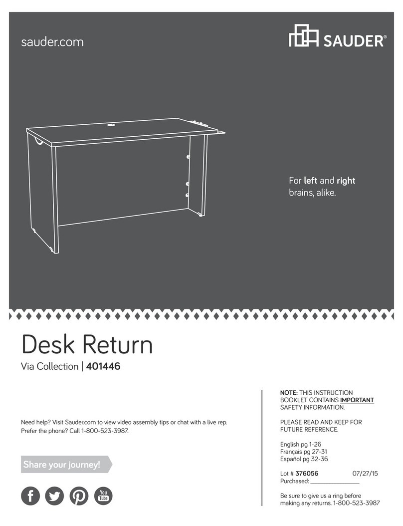
Corner Desk
Costa Collection | Model 430237
Sit and surf.
Table of Contents Assembly Tools Required
Part Identification
Hardware Identification
Hardware Usage Guide
Assembly Steps
Français
Español
Safety
Warranty
No. 2 Phillips Screwdriver
Tip Shown Actual Size
2-3
4-5
7, 34, 52
6-63
64-72
73-80
81-82
83
åWhile not all parts are labeled, some of the parts will have a label or an inked letter on the edge
to help distinguish similar parts from each other. Use this part identification to help identify similar parts.
A RIGHT END (1)
B LEFT END (1)
B61 DRAWER BOTTOM (1)
C SMALL TOP (1)
D TOP (1)
D78 DRAWER BACK (1)
D583 RIGHT DRAWER SIDE (1)
D584 LEFT DRAWER SIDE (1)
E END (1)
F END MOLDING (3)
G LEFT PANEL (1)
H RIGHT FRONT LEG (2)
J BOTTOM MOLDING (1)
K ADJUSTABLE SHELF (1)
L SHELF (1)
M BOTTOM (1)
N BACK (1)
O RIGHT PANEL (1)
P LEFT FRONT LEG (2)
Q LEFT MODESTY PANEL (1)
R RIGHT MODESTY PANEL (1)
S RIGHT REAR LEG (1)
T LEFT REAR LEG (1)
U DRAWER FRONT (1)
Now you know
our ABCs.
Part Identification
Electric drill with 1/8"
(ONLY in indicated step)
Masking Tape
Scissors
430237 www.sauder.com/servicePage 2
Part Identification
A
B
C
D
E
F
F
F
G
H
H
J
K
L
M
N
O
P
P
Q
R
S
T
U
B61
D78 D583
D584
430237www.sauder.com/service Page 3
Hardware Identification
åScrews are shown actual size. You may receive extra hardware with your unit.
1P GROMMET
CAP - 1
1R METAL PIN - 4
8F CAM SCREW - 22 15F WOOD DOWEL - 12
10P GROMMET - 2
1F HIDDEN CAM - 29
2F CAM DOWEL - 7
2R RUBBER
SLEEVE - 4
KNOB SET - 1
136K
37F TWIST-LOCK®
FASTENER - 19
14G CONNECTOR PLATE - 1
(EXTENSION SET SHOWN SEPARATED)
VEXTENSION
RAIL - 2 WEXTENSION
SLIDE - 2
93P APPLIQUE
CARD - 3
FILE GLIDE - 2
23B
4P CORD CLIP - 2
430237 www.sauder.com/servicePage 4
Hardware Identification
åScrews are shown actual size. You may receive extra hardware with your unit.
9S BLACK 1-1/8" PAN HEAD SCREW - 6
21S BLACK 1-1/8" MACHINE SCREW - 1
1S BLACK 9/16" LARGE HEAD SCREW - 8
6S BROWN 7/16" LARGE HEAD SCREW - 4
32S BLACK 9/16" FLAT HEAD SCREW - 6 BLACK 1-15/16" FLAT HEAD SCREW - 7
113S
30S BLACK 1-9/16" FLAT HEAD SCREW - 4
3S GOLD 5/16" FLAT HEAD SCREW - 4
430237www.sauder.com/service Page 5
Step 1 Look for this icon. It means a video assembly tip is
available at www.sauder.com/service/tips
Find the numbered video or scan the QR code. 0
å Assemble your unit on a carpeted floor or on the empty carton to avoid scratching your
unit or the floor.
å Turn two BLACK 9/16" FLAT HEAD SCREWS (32S) into the LEFT END (B) until the
shoulders of the SCREWS rest on the surface of the LEFT END.
å NOTE: Do not overtighten the SCREWS.
å Slide one of the END MOLDINGS (F) onto the LEFT END (B). Line up the groove in the
MOLDING over the heads of the SCREWS in the LEFT END.
å NOTE: The MOLDING should be even on both edges of the LEFT END.
å NOTE: If the MOLDING comes up o of the SCREWS, remove it and slide it on again.
Shoulder
Apply pressure with your hands
as you guide the MOLDING over
the SCREWS and onto the END.
BLACK 9/16" FLAT HEAD SCREW
(2 used in this step)
32S
BF
Surface with fewer holes
430237 www.sauder.com/servicePage 6
Hardware Usage Guide
1. Insert the dowel end of the FASTENER into the
hole of the adjoining part.
NOTE: The dowel end of the FASTENER must
remain fully inserted in the hole of the adjoining
part while locking the FASTENER.
2. Tighten the FASTENER with a Phillips
screwdriver as tight as possible.
Dowel end
2.
Push a TWIST-LOCK® FASTENER
into the large hole in the part.
1.
HOW TO USE A TWIST-LOCK®FASTENER
Cam Screw
Hidden Cam
Arrow
Push a HIDDEN CAM into
the part. The arrow in the
HIDDEN CAM must point
toward the hole in the
edge of the board.
Hole
2. 3.
1
2
Insert the CAM SCREW into the HIDDEN CAM.
Tighten the HIDDEN CAM.
HOW TO USE A HIDDEN CAM & CAM SCREW
Turn the CAM SCREW until
the shoulder is against the
surface of the part.
1.
430237www.sauder.com/service Page 7
Step 2
å Push two SAUDER TWIST-LOCK® FASTENERS (37F) into
the large holes in the LEFT END (B).
å Push six HIDDEN CAMS (1F) into the LEFT END (B).
37F
2
Do not tighten the TWIST-LOCK® FASTENERS in this step.
B
1
1F
Arrow
1F
Arrow
1
2
430237 www.sauder.com/servicePage 8
å Turn eight CAM SCREWS (8F) into one of the LEFT
FRONT LEGS (P) and the LEFT REAR LEG (T).
Step 3
T
P
1
8F
8F
430237www.sauder.com/service Page 9
Step 4
å Insert one WOOD DOWEL (15F) into the LEFT FRONT LEG (P).
å Fasten the LEFT END (B) to the LEFT FRONT LEG (P). Tighten three HIDDEN CAMS.
å Insert one WOOD DOWEL (15F) into the LEFT REAR LEG (T).
å Fasten the LEFT REAR LEG (T) to the LEFT END (B). Tighten three HIDDEN CAMS.
å NOTE: Be sure the WOOD DOWELS in the LEGS insert into the LEFT END.
15F
Surface with HIDDEN CAMS
B
P
T
1
These surfaces
should be even.
Edge with
TWIST-LOCK®
FASTENERS End without hole
End without hole
These surfaces
should be even.
430237 www.sauder.com/servicePage 10
å Separate the EXTENSION SLIDES (W) from the EXTENSION RAILS (V) as shown in the upper diagram below.
Be prepared, the parts are greasy.
å Fasten one EXTENSION RAIL (V) to the LEFT END (B). Use two GOLD 5/16" FLAT HEAD SCREWS (3S).
å NOTE: For the EXTENSION RAIL, turn a SCREW into the hole shown in the enlarged diagram. Then, slide the
inner cartridge of the EXTENSION RAIL in to find the other hole that lines up with the hole in the END.
Turn a SCREW into this hole.
å NOTE: The EXTENSION SLIDES will be used later for the DRAWER.
Step 5
B
V
Push the black lever in and pull the SLIDE from the RAIL.
W
V
Open end
Leg with CAM SCREWS
7
430237www.sauder.com/service Page 11
GOLD 5/16" FLAT HEAD SCREW
(2 used in this step)
3S
Step 6
å Push one SAUDER TWIST-LOCK® FASTENER (37F) into
the large hole in the BACK (N).
å Push four HIDDEN CAMS (1F) into the BACK (N).
37F
2
Do not tighten the TWIST-LOCK® FASTENERS in this step.
N
1
1F
Arrow
1F
Arrow
1
2
430237 www.sauder.com/servicePage 12
å Insert one GROMMET (10P) into the large hole
in the BACK (N).
å Fasten the BACK (N) to the LEFT REAR LEG (T). Tighten two
HIDDEN CAMS.
Step 7
Do not stand the unit upright without the
BACK fastened. The unit may collapse.
Caution
N
1
Surface with HIDDEN CAMS
Edge with
TWIST-LOCK®
FASTENERS
10P
430237www.sauder.com/service Page 13
T
å Push eight SAUDER TWIST-LOCK® FASTENERS (37F)
into the large holes in the SHELF (L) and BOTTOM (M).
Step 8
L
M
37F
37F
2
Do not tighten the TWIST-LOCK® FASTENERS in this step.
430237 www.sauder.com/servicePage 14
å Fasten the SHELF (L) and BOTTOM (M) to the LEFT END (B).
Tighten four TWIST-LOCK® FASTENERS.
å Fasten the BOTTOM (M) to the BACK (N). Use one BLACK
1-15/16" FLAT HEAD SCREW (113S).
Step 9
L
B
M
Notched edge
Surface with
TWIST-LOCK®
FASTENERS
Surface with
TWIST-LOCK®
FASTENERS
2
BLACK 1-15/16" FLAT HEAD SCREW
(1 used in this step)
113S
N
430237www.sauder.com/service Page 15
Finished edge
Step 10
å Slide the BOTTOM MOLDING* (J) onto the notched edge
of the BOTTOM (M).
å *U.S. Patent No. 5,499,886
M
J
Slide the BOTTOM MOLDING (J)
onto the notched edge.
The groove
is closer to
this edge.
Notched edge
These surfaces should be even.
430237 www.sauder.com/servicePage 16
Step 11
å Turn two BLACK 9/16" FLAT HEAD SCREWS (32S) into the RIGHT END (A) until the
shoulders of the SCREWS rest on the surface of the RIGHT END.
å NOTE: Do not overtighten the SCREWS.
å Slide one END MOLDING (F) onto the RIGHT END (A). Line up the groove in the
MOLDING over the heads of the SCREWS in the RIGHT END.
å NOTE: The MOLDING should be even on both edges of the RIGHT END.
å NOTE: If the MOLDING comes up o of the SCREWS, remove it and slide it on again.
Shoulder
Apply pressure with your hands
as you guide the MOLDING over
the SCREWS and onto the END.
BLACK 9/16" FLAT HEAD SCREW
(2 used in this step)
32S
AF
Surface with fewer holes
430237www.sauder.com/service Page 17
Step 12
å Push two SAUDER TWIST-LOCK® FASTENERS (37F) into
the large holes in the RIGHT END (A).
å Push six HIDDEN CAMS (1F) into the RIGHT END (A).
37F
2
Do not tighten the TWIST-LOCK® FASTENERS in this step.
A
1
1F
Arrow
1F
Arrow
1
2
430237 www.sauder.com/servicePage 18
Step 13
å Turn eight CAM SCREWS (8F) into one of the RIGHT
FRONT LEGS (H) and the RIGHT REAR LEG (S).
H
S
1
8F
8F
430237www.sauder.com/service Page 19
Step 14
H
A
S
å Insert one WOOD DOWEL (15F) into the RIGHT REAR LEG (S).
å Fasten the RIGHT END (A) to the RIGHT REAR LEG (S). Tighten three HIDDEN CAMS.
å Insert one WOOD DOWEL (15F) into the RIGHT FRONT LEG (H).
å Fasten the RIGHT FRONT LEG (H) to the RIGHT END (A). Tighten three HIDDEN CAMS.
å NOTE: Be sure the WOOD DOWELS in the LEGS insert into the RIGHT END.
15F
Surface with HIDDEN CAMS
1
These surfaces
should be even.
Edge with
TWIST-LOCK®
FASTENERS End without hole
End without hole
These surfaces
should be even.
430237 www.sauder.com/servicePage 20

Other Sauder Indoor Furnishing manuals
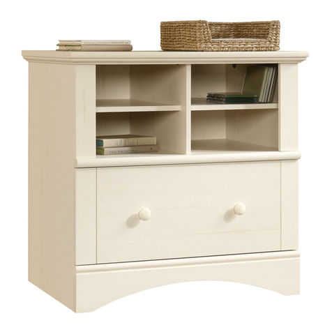
Sauder 401822 User manual

Sauder

Sauder 401822 User manual

Sauder 430628 User manual

Sauder

Sauder 430628 User manual

Sauder Carson Forge 415520 User manual
Sauder

Sauder Carson Forge 415520 User manual

Sauder Harbor View 401685 User manual

Sauder

Sauder Harbor View 401685 User manual

Sauder 423493 User manual

Sauder

Sauder 423493 User manual

Sauder Beginnings 415544 User manual

Sauder

Sauder Beginnings 415544 User manual

Sauder HomePlus 422428 User manual

Sauder

Sauder HomePlus 422428 User manual

Sauder 422807 User manual

Sauder

Sauder 422807 User manual

Sauder OFFICE WORKS AFFIRM 427431 User manual

Sauder

Sauder OFFICE WORKS AFFIRM 427431 User manual

Sauder Edge Water Series User manual

Sauder

Sauder Edge Water Series User manual

Sauder Harbor View 158015 User manual

Sauder

Sauder Harbor View 158015 User manual

Sauder Anywhere Console 419230 User manual

Sauder

Sauder Anywhere Console 419230 User manual

Sauder Craft Pro 421405 User manual

Sauder

Sauder Craft Pro 421405 User manual

Sauder Briarbrook 430077 User manual

Sauder

Sauder Briarbrook 430077 User manual
Sauder Edge Water 409047 User manual

Sauder

Sauder Edge Water 409047 User manual

Sauder Portage Park 427478 User manual

Sauder

Sauder Portage Park 427478 User manual

Sauder 419119 User manual

Sauder

Sauder 419119 User manual

Sauder Stockbridge 409128 User manual

Sauder

Sauder Stockbridge 409128 User manual

Sauder 413044 User manual

Sauder

Sauder 413044 User manual

Sauder 433242 User manual

Sauder

Sauder 433242 User manual

Sauder 412091 User manual

Sauder

Sauder 412091 User manual

Sauder 419198 User manual

Sauder

Sauder 419198 User manual

Sauder Soft Modern 415007 User manual

Sauder

Sauder Soft Modern 415007 User manual

Sauder WHISKER User manual

Sauder

Sauder WHISKER User manual

Popular Indoor Furnishing manuals by other brands

KIMANO QUBA MOD.132 manual

KIMANO

KIMANO QUBA MOD.132 manual

Donco 215 Assembly & instruction manual

Donco

Donco 215 Assembly & instruction manual

Safavieh Furniture Jamison AMH1535A quick start guide

Safavieh Furniture

Safavieh Furniture Jamison AMH1535A quick start guide

CAMERICH STILTS-07 Install Instruction

CAMERICH

CAMERICH STILTS-07 Install Instruction

Belmont D Series installation manual

Belmont

Belmont D Series installation manual

Emmezeta BUGK231B Assembling Instruction

Emmezeta

Emmezeta BUGK231B Assembling Instruction

Micasa Mood manual

Micasa

Micasa Mood manual

Winners Only T2-VT100S-G Assembly instructions

Winners Only

Winners Only T2-VT100S-G Assembly instructions

Westwood Design Donnington Assembly instruction

Westwood Design

Westwood Design Donnington Assembly instruction

Better Homes and Gardens DOVER BH17-084-098-28 Assembly instructions

Better Homes and Gardens

Better Homes and Gardens DOVER BH17-084-098-28 Assembly instructions

Union Home ALDEN DIN00197 quick start guide

Union Home

Union Home ALDEN DIN00197 quick start guide

Habitat Sofia 817707 manual

Habitat

Habitat Sofia 817707 manual

Pfister DELTA 29197 quick start guide

Pfister

Pfister DELTA 29197 quick start guide

Next BRONX 635747 Assembly instructions

Next

Next BRONX 635747 Assembly instructions

MOEBE Frame Assembly instructions

MOEBE

MOEBE Frame Assembly instructions

Dorel Home Products 4071449 manual

Dorel Home Products

Dorel Home Products 4071449 manual

Core Products HARVARD HR902 manual

Core Products

Core Products HARVARD HR902 manual

Rauch 45698.1130 Assembly instructions

Rauch

Rauch 45698.1130 Assembly instructions

manuals.online logo
manuals.online logoBrands
  • About & Mission
  • Contact us
  • Privacy Policy
  • Terms and Conditions

Copyright 2025 Manuals.Online. All Rights Reserved.