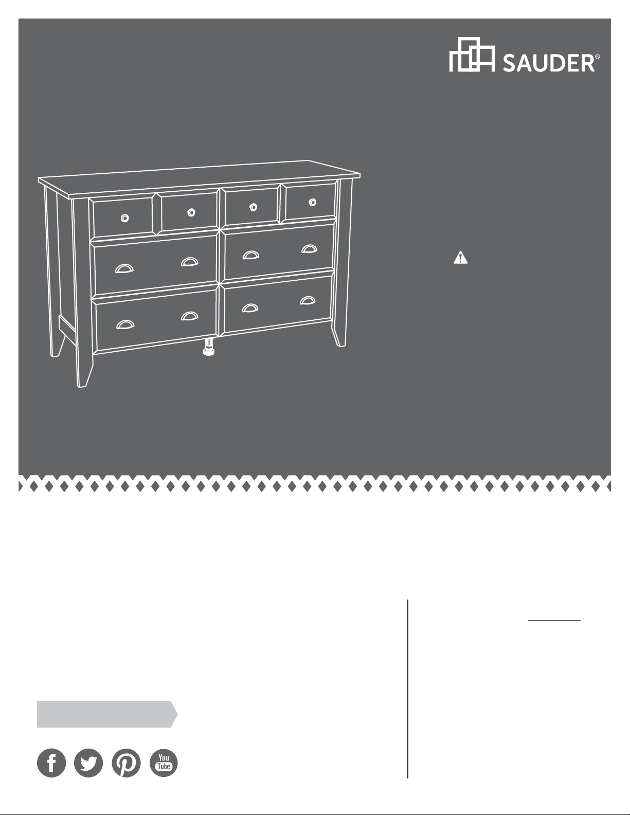
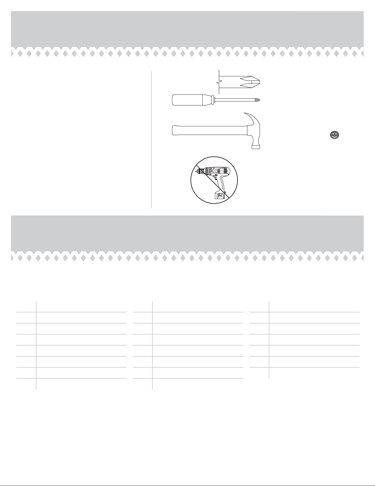
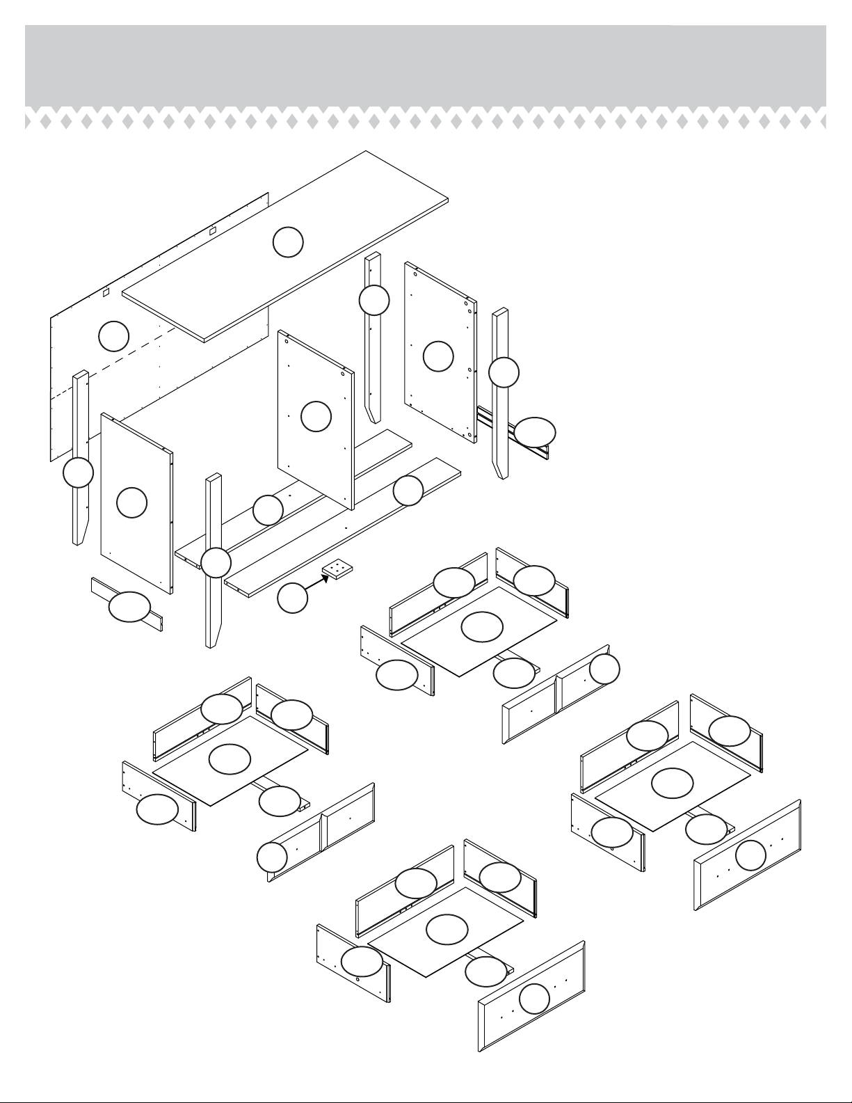
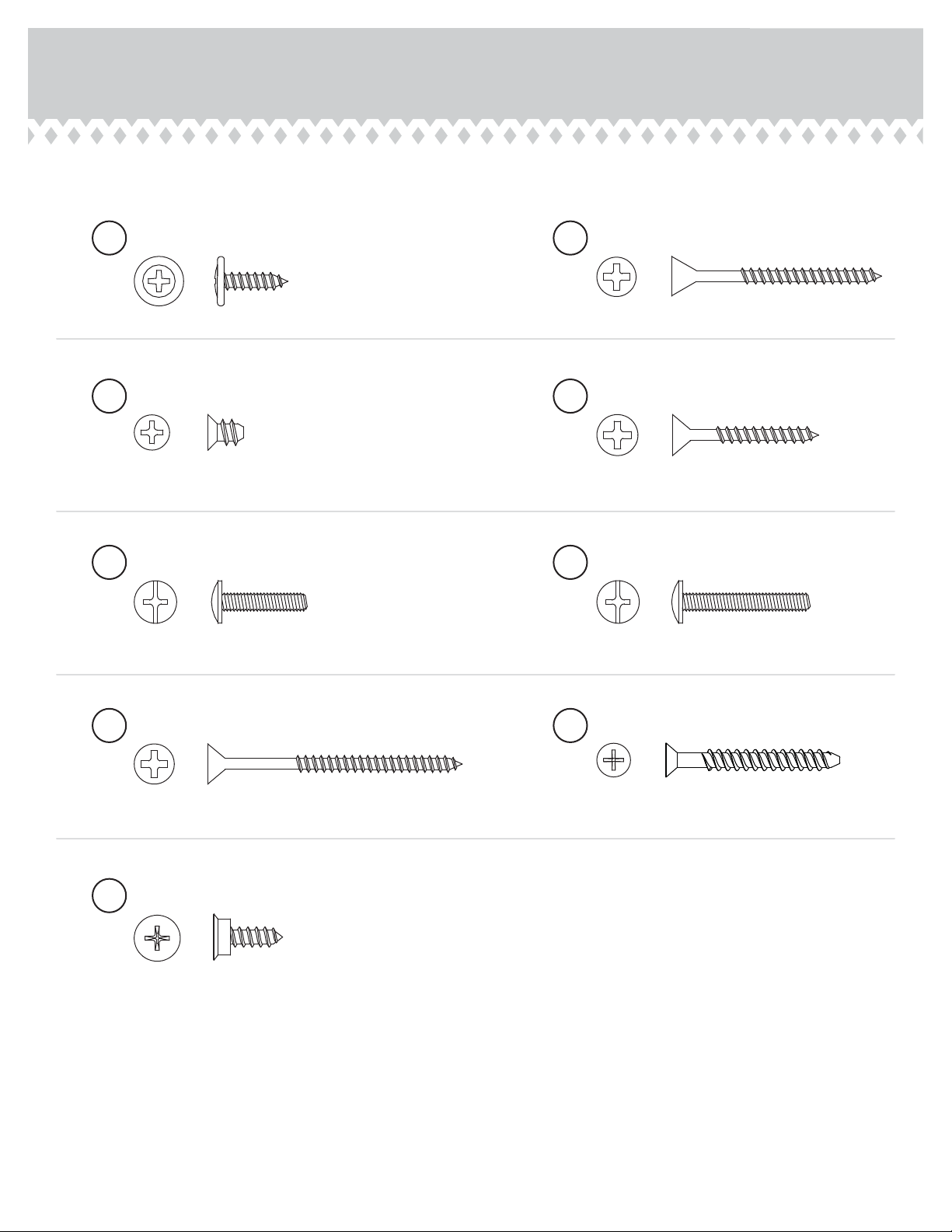
Sauder Shoal Creek 411201 User manual
Other Sauder Indoor Furnishing manuals

Sauder
Sauder Shoal Creek 418655 User manual

Sauder
Sauder Whitaker Point 429366 User manual

Sauder
Sauder 423392 User manual

Sauder
Sauder Worksense BERGEN CIRCLE 426289 User manual

Sauder
Sauder Corner Entertainment Credenza 403818 User manual

Sauder
Sauder Edge Water Credenza 415321 User manual

Sauder
Sauder 402159 User manual

Sauder
Sauder Worksense BERGEN CIRCLE 426906 User manual

Sauder
Sauder Primary Street 418388 User manual

Sauder
Sauder North Avenue 422097 User manual

Sauder
Sauder Soft Modern 415007 User manual

Sauder
Sauder OfficeWorks AFFIRM 426285 User manual

Sauder
Sauder Carson Forge Collection 415117 User manual

Sauder
Sauder Cannery Bridge 429556 User manual

Sauder
Sauder Boulevard Cafe 427354 User manual

Sauder
Sauder 420567 User manual

Sauder
Sauder Cannery Bridge 429554 User manual

Sauder
Sauder North Avenue 426016 User manual

Sauder
Sauder worksense BERGEN CIRCLE 426290 User manual

Sauder
Sauder worksense Bergen Circle 426278 User manual


Popular Indoor Furnishing manuals by other brands

Regency
Regency LWMS3015 Assembly instructions

Furniture of America
Furniture of America CM7751C Assembly instructions

Safavieh Furniture
Safavieh Furniture Estella CNS5731 manual

PLACES OF STYLE
PLACES OF STYLE Ovalfuss Assembly instruction

Trasman
Trasman 1138 Bo1 Assembly manual

Costway
Costway JV10856 manual