manuals.online logo
Brands
  1. Home
  2. •
  3. Brands
  4. •
  5. Sauder
  6. •
  7. Indoor Furnishing
  8. •
  9. Sauder Cannery Bridge 424192 User manual

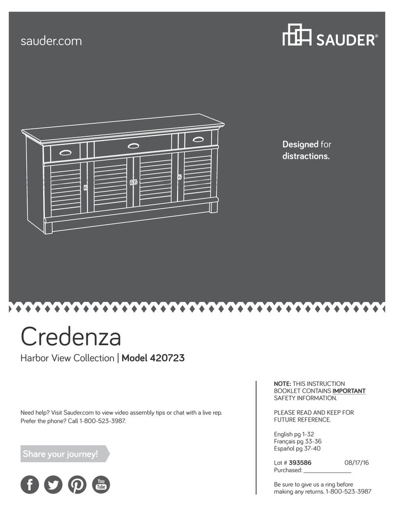
Sauder Cannery Bridge 424192 User manual

NOTE: THIS INSTRUCTION
BOOKLET CONTAINS IMPORTANT
SAFETY INFORMATION.
PLEASE READ AND KEEP FOR
FUTURE REFERENCE.
English pg 1-22
Français pg 23-25
Español pg 26-28
Lot # 529913 06/13/19
Purchased: __________________
Be sure to give us a ring before
making any returns. 1-800-523-3987
Storage Wall
Cannery Bridge Collection | Model 424192
Need help? Visit Sauder.com to view video assembly tips or chat with a live rep.
Prefer the phone? Call 1-800-523-3987.
Share your journey!
sauder.com
Knick-knack
paddywhack,
give your stu a home.
Table of Contents Assembly Tools Required
2-3
4
5-22
23-25
26-28
29-30
31
Part Identification
Hardware Identification
Assembly Steps
Français
Español
Safety
Warranty
Hammer
Not actual size
No. 2 Phillips Screwdriver
Tip Shown Actual Size
424192 www.sauder.com/servicesPage 2
Part Identification
åWhile not all parts are labeled, some of the parts will have a label or an inked letter on the edge
to help distinguish similar parts from each other. Use this part identification to help identify similar parts.
A RIGHT END (1)
B LEFT END (1)
C RIGHT UPRIGHT (1)
D LEFT UPRIGHT (1)
E LARGE UPRIGHT (2)
F3 TOP (1)
G2 BOTTOM (1)
H2 SHELF (1)
I BACK (1)
J DOOR (3)
K ADJUSTABLE SHELF (6)
L FRONT LEG (2)
M REAR LEG (2)
N BASE (1)
P UPRIGHT MOLDING (2)
Q UPPER END MOLDING (2)
R SHELF MOLDING (2)
S SUPPORT (1)
T SIDE SUPPORT (2)
U END MOLDING (2)
Part Identification Now you know
our ABCs.
424192www.sauder.com/services Page 3
A
B
C
D
E
F3
G2
H2
I
J
K
L
M
N
U
P
Q
R
S
T
J
J
T
U
Q
L
M
E
P
K
R
K
K
K
K
Hardware Identification
åScrews are shown actual size. You may receive extra hardware with your unit.
424192 www.sauder.com/servicesPage 4
LARGE METAL
BRACKET - 2
1G
BLACK 9/16" LARGE HEAD SCREW - 26
1S
BLACK 7/8" MACHINE SCREW - 3
37S
RUBBER
SLEEVE - 24
2R
METAL
PIN - 24
1R
BLACK 1/2" FLAT HEAD SCREW - 12
11S
BLACK 9/16" FLAT HEAD SCREW - 8
32S
CAM SCREW - 14
8F
DOOR STOP - 3
4I
NAIL - 82
1N
HIDDEN CAM - 30
1F CAM DOWEL - 16
2F
100S BLACK 2-3/4" FLAT HEAD SCREW - 8 BLACK 1-15/16" FLAT HEAD SCREW - 12
113S
METAL
BRACKET - 11
4G
14H CURVED HINGE - 4 40H HINGE - 2 KNOB - 3
178K
APPLIQUE
CARD - 2
91P FURNITURE TIPPING
RESTRAINT KIT - 1
97
Step 1 Look for this icon. It means a
video assembly tip is available at
www.sauder.com/services/tips
å Assemble your unit on a carpeted floor or on the empty
carton to avoid scratching your unit or the floor.
å Push sixteen HIDDEN CAMS (1F) into the UPRIGHTS (C
and D), TOP (F3), BOTTOM (G2), and SHELF (H2). Then,
insert the metal end of a CAM DOWEL (2F) into each
HIDDEN CAM.
424192www.sauder.com/services Page 5
Insert the metal end of the CAM
DOWEL into the HIDDEN CAM.
Arrow
Do not tighten the HIDDEN CAMS in this step.
C
D
F3
G2
H2
Arrow
1F
2F
(16 used)
Step 2
424192 www.sauder.com/servicesPage 6
8F
å Push fourteen HIDDEN CAMS (1F) into the holes in the
ENDS (A and B) and LARGE UPRIGHTS (E).
å Turn fourteen CAM SCREWS (8F) into the FRONT
LEGS (L) and UPRIGHT MOLDINGS (P).
Remember:
Righty tighty.
Lefty loosey.
(14 used)
L
P
L
P
Arrow
1F
1F
Arrow
A
B
Arrow
Ex 2
(14 used) Hole
The arrow in the HIDDEN
CAM must point toward the
hole in the edge of the board.
Step 3
424192www.sauder.com/services Page 7
å Turn the ENDS (A and B) over.
å Turn eight BLACK 9/16" FLAT HEAD SCREWS (32S) into the ENDS (A and B) until the shoulders of the SCREWS rest on
the surfaces of the ENDS.
å Slide the MOLDINGS (Q and U) onto the ENDS (A and B). Line up the grooves in the MOLDINGS over the heads of the
SCREWS in the ENDS.
å NOTE: The END MOLDINGS (U) are wider than the UPPER END MOLDINGS (Q).
å NOTE: Be sure to place the MOLDINGS in the exact locations shown below.
These edges
should be even.
These edges
should be even.
These edges
should be even.
Shoulder
BLACK 9/16" FLAT HEAD SCREW
(8 used in this step)
32S
BLACK 9/16" FLAT HEAD SCREW
32S
A
B
U
Q
U
Q
Surface
without
HIDDEN
CAMS
Surface
without
HIDDEN
CAMS
Edge with smaller holes
Apply pressure with your hands
as you guide the MOLDINGS over
the SCREWS and onto the ENDS.
Step 4
424192 www.sauder.com/servicesPage 8
å Fasten the LEFT END (B) to a FRONT LEG (L) as shown in the upper diagram. Tighten four HIDDEN CAMS.
å Fasten a REAR LEG (M) to the LEFT END (B). Use four BLACK 2-3/4" FLAT HEAD SCREWS (100S).
å Repeat this step using the RIGHT END (A) as shown in the lower diagram.
L
L
A
B
M
M
This hole
must be here.
These surfaces
should be even.
These surfaces
should be even.
This hole
must be here.
BLACK 2-3/4" FLAT HEAD SCREW
(8 used in this step)
100S
1
2
Surface with HIDDEN CAMS
Step 5
424192www.sauder.com/services Page 9
Start Tighten
Arrow
Minimum
190 degrees
Caution
Risk of damage or
injury. HIDDEN CAMS
must be completely
tightened. HIDDEN
CAMS that are not
completely tightened
may loosen, and parts
may separate. To
completely tighten:
Arrow
Maximum
210 degrees
å Open the FURNITURE TIPPING RESTRAINT KIT (97) and
fasten the SAFETY STRAP to the TOP (F3). Use the provided
BLACK 9/16" LARGE HEAD SCREW.
å NOTE: Position the SAFETY STRAP exactly as shown.
å Fasten the TOP (F3) and SHELF (H2)
to the LEFT END (B). Tighten
four HIDDEN CAMS.
L
B
Surface with
HIDDEN CAMS
H2
F3
F3
Surface without
HIDDEN CAMS
Notched edge
Notched edge
Surface with
HIDDEN CAMS
Do not stand the unit upright without the
BACK fastened. The unit may collapse.
Caution
BLACK 9/16" LARGE HEAD SCREW
(1 used in this step)
Safety strap
97
Surface with
HIDDEN CAMS
Step 6
424192 www.sauder.com/servicesPage 10
H2
F3
Notched edge
Notched edge
å Slide the SHELF MOLDINGS* (R) onto the notched edges
of the TOP (F3) and SHELF (H2).
å *U.S. Patent No. 5,499,886
Slide the SHELF MOLDING (R) onto the notched edge.
Slide the SHELF MOLDING (R)
onto the notched edge.
R
R
The large
groove is closer
to this edge.
å Fasten the LARGE UPRIGHTS (E) to the TOP (F3) and
SHELF (H2). Use eight BLACK 1-15/16" FLAT
HEAD SCREWS (113S).
å Fasten the UPRIGHT MOLDINGS (P) to the LARGE
UPRIGHTS (E). Tighten six HIDDEN CAMS.
Step 7
424192www.sauder.com/services Page 11
H2
F3
E
P
E
P
Surface with HIDDEN CAMS
Surface with
HIDDEN CAMS
Edge with HIDDEN CAMS
BLACK 1-15/16" FLAT HEAD SCREW
(8 used in this step)
113S
BLACK 1-15/16" FLAT HEAD SCREW
113S
Step 8
å Fasten the UPRIGHTS (C and D) to the SHELF (H2).
Tighten four HIDDEN CAMS.
424192 www.sauder.com/servicesPage 12
Arrow
Minimum
190 degrees
Maximum
210 degrees
C
H2
Surface with
HIDDEN CAMS
Surface with
HIDDEN CAMS
D
Finished edge
Don't worry. It isn't
Rome. This can be built
in a day.
å Fasten the BOTTOM (G2) to the LEFT END (B). Tighten
two HIDDEN CAMS.
å Fasten the BOTTOM (G2) to the UPRIGHTS (C and D).
Use four BLACK 1-15/16" FLAT HEAD SCREWS (113S).
å Push the DOOR STOPS (4I) into the holes in
the UPRIGHTS (C and D).
Step 9
424192www.sauder.com/services Page 13
Arrow
Minimum
190 degrees
Maximum
210 degrees
Surface with
HIDDEN CAMS
G2
D
C
4I
4I
These holes
must be here.
B
BLACK 1-15/16" FLAT HEAD SCREW
(4 used in this step)
113S
Step 10
å Fasten the RIGHT END (A) to the TOP (F3), BOTTOM (G2),
and SHELF (H2). Tighten six HIDDEN CAMS.
424192 www.sauder.com/servicesPage 14
L
A
Surface without
HIDDEN CAMS
H2
F3
G2
Arrow
Minimum
190 degrees
Maximum
210 degrees
å Fasten the LARGE METAL BRACKETS (1G) to the BASE (N).
Use two BLACK 9/16" LARGE HEAD SCREWS (1S).
å Fasten three METAL BRACKETS (4G) to the BOTTOM (G2).
Use three BLACK 9/16" LARGE HEAD SCREWS (1S).
å NOTE: Be sure the METAL BRACKETS are even with the
long edge of the BOTTOM.
å Fasten the BASE (N) to the ENDS (A and B). Use two BLACK
9/16" LARGE HEAD SCREWS (1S) through the lower set of
holes in the LARGE METAL BRACKETS and into the ENDS.
å NOTE: You will fasten the BASE to the BOTTOM in the
next step.
Step 11
424192www.sauder.com/services Page 15
A
B
G2
BLACK 9/16" LARGE HEAD SCREW
(7 used in this step)
1S
1G
1G
N
N
4G
Step 12
424192 www.sauder.com/servicesPage 16
å Carefully turn your unit over onto its front edges. Fasten the
BASE (N) to the BOTTOM (G2). Use three BLACK 9/16" LARGE
HEAD SCREWS (1S) through the LARGE METAL BRACKETS
and into the BASE.
å NOTE: You may need help from another person to help get your
back centered on the unit.
å Unfold the BACK (I) and lay it over your unit.
å Make equal margins along the top and bottom edges of the
BACK (I). Then, make equal margins along the side edges of
the BACK (I). Push on opposite corners of your unit if needed to
make it "square".
å Fasten the BACK (I) to your unit using the NAILS (1N).
å NOTE: Be sure to tap NAILS into the holes that line up over the
UPRIGHTS (C, D, and E) and SHELF (H2).
Unfinished
surface
NAIL
(82 used for the BACK)
1N
These holes must line up over the
UPRIGHTS (C, D, and E) and SHELF (H2).
I
Do not stand the unit upright without the
BACK fastened. The unit may collapse.
Caution
BLACK 9/16" LARGE HEAD SCREW
(3 used for the BASE)
1S
G2
N
å Fasten eight METAL BRACKETS (4G) to the
SUPPORTS (S and T). Use eight BLACK 9/16" LARGE
HEAD SCREWS (1S).
å NOTE: Be sure the METAL BRACKETS are even with
the edges of the SUPPORTS.
å Fasten the SUPPORTS (S and T) to the BOTTOM (G2).
Use six BLACK 9/16" LARGE HEAD SCREWS (1S)
through the METAL BRACKETS and into the BOTTOM.
å Fasten the SIDE SUPPORTS (T) to the SUPPORT (S).
Use two BLACK 9/16" LARGE HEAD SCREWS (1S)
through the METAL BRACKETS and into the SUPPORT.
Step 13
424192www.sauder.com/services Page 17
S
T
T
S
T
T
G2
BLACK 9/16" LARGE HEAD SCREW
(16 used in this step)
1S
(8 used)
4G
4G
4G
Step 14
å Fasten four CURVED HINGES (14H) to two DOORS (J). Use
eight BLACK 1/2" FLAT HEAD SCREWS (11S).
å Fasten two HINGES (40H) to the remaining DOOR (J). Use
four BLACK 1/2" FLAT HEAD SCREWS (11S).
424192 www.sauder.com/servicesPage 18
BLACK 1/2" FLAT HEAD SCREW
(12 used in this step)
11S
14H
J
J
J
HINGE
CURVED HINGE
40H
Step 15
424192www.sauder.com/services Page 19
å Carefully stand your unit upright.
å Before fastening the DOOR to your unit, be sure the mounting
screw is against the stops as shown in the right diagram. If it isn't,
loosen the mounting screw to slide it against the stops. Then tighten
the mounting screw.
å First, fasten the DOOR (J) with HINGES (40H) to the RIGHT
UPRIGHT (C). Use the screws in the HINGES. You should start each
SCREW a few turns before completely tightening any of them.
å NOTE: Tighten the adjusting SCREWS completely in to center this
DOOR between the UPRIGHTS.
å Fasten the DOORS (J) with CURVED HINGES (14H) to the ENDS (A and B).
Use the screws in the HINGES. You should start each SCREW a few turns
before completely tightening any of them.
å Fasten a KNOB (178K) to each DOOR (J). Use three BLACK 7/8"
MACHINE SCREW (37S).
å See the next step for additional
DOOR adjustments.
BLACK 7/8" MACHINE SCREW
(3 used for the KNOBS)
37S
Pro Tip: Lift with your
legs. And, you know,
your arms.
C
A
DOOR (J)
with CURVED
HINGES (14H)
DOOR (J)
with CURVED
HINGES (14H)
JJ
J
B
OR
Adjusting
screw
Mounting
screw
Stop
Hinge
Curved
edge
DOOR (J) with HINGES (40H)
178K
178K
Step 16
424192 www.sauder.com/servicesPage 20
å Refer to the enlarged diagram to identify the parts on the HINGES.
å The DOORS may need some adjustments. Follow the text below to make needed adjustments.
å DOOR ADJUSTMENTS:
To adjust the DOORS from side to side (horizontal), turn the adjusting screw in or out.
å To adjust the DOORS up and down (vertical), loosen both vertical adjustment screws. Move the DOORS up or down to the
desired location. Tighten the screws after making adjustments.
å To adjust the DOORS in or out (depth), loosen the mounting screw one turn and move the DOORS in or out, as needed.
Tighten the mounting screw after making adjustments.
(vertical adjustment)
Adjusting screw (horizontal)
Mounting screw (depth)

Other Sauder Indoor Furnishing manuals
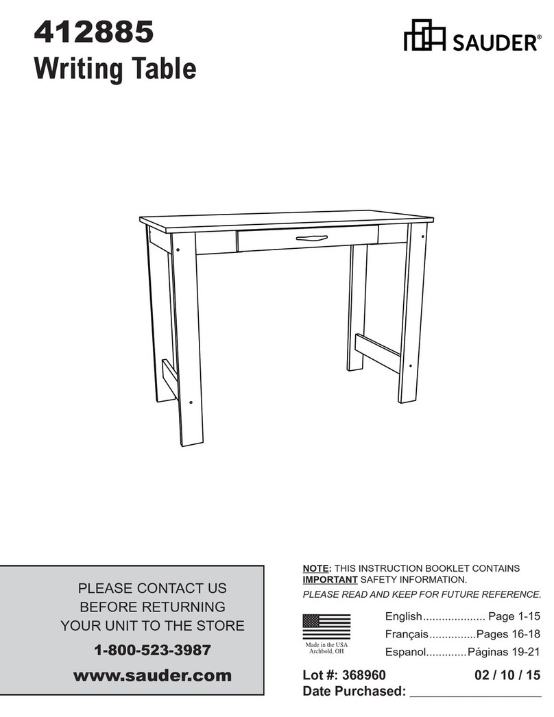
Sauder Camden 101730 User manual

Sauder

Sauder Camden 101730 User manual

Sauder Cottage Road 416039 User manual

Sauder

Sauder Cottage Road 416039 User manual

Sauder North Avenue 420032 User manual

Sauder

Sauder North Avenue 420032 User manual

Sauder Hammond 423531 User manual

Sauder

Sauder Hammond 423531 User manual

Sauder Beginnings Series User manual

Sauder

Sauder Beginnings Series User manual

Sauder WHISKER User manual

Sauder

Sauder WHISKER User manual

Sauder Hammond 430786 User manual

Sauder

Sauder Hammond 430786 User manual

Sauder 403785 User manual

Sauder

Sauder 403785 User manual

Sauder 416821 User manual

Sauder

Sauder 416821 User manual

Sauder Edge Water 422406 User manual

Sauder

Sauder Edge Water 422406 User manual

Sauder Carson Forge 412921 User manual

Sauder

Sauder Carson Forge 412921 User manual

Sauder North Avenue 422313 User manual

Sauder

Sauder North Avenue 422313 User manual

Sauder Steel River 427855 User manual

Sauder

Sauder Steel River 427855 User manual

Sauder Whitaker Point 429374 User manual

Sauder

Sauder Whitaker Point 429374 User manual

Sauder 422293 User manual

Sauder

Sauder 422293 User manual

Sauder Clifford Place 433360 User manual

Sauder

Sauder Clifford Place 433360 User manual

Sauder North Avenue 420050 User manual

Sauder

Sauder North Avenue 420050 User manual

Sauder Rollingwood 431407 User manual

Sauder

Sauder Rollingwood 431407 User manual

Sauder 419119 User manual

Sauder

Sauder 419119 User manual

Sauder Shoal Creek 409733 User manual

Sauder

Sauder Shoal Creek 409733 User manual

Sauder OfficeWorks AFFIRM 427422 User manual

Sauder

Sauder OfficeWorks AFFIRM 427422 User manual

Sauder 420449 User manual

Sauder

Sauder 420449 User manual

Sauder Briarbrook 430072 User manual

Sauder

Sauder Briarbrook 430072 User manual

Sauder The Edge Water 409045 User manual

Sauder

Sauder The Edge Water 409045 User manual

Popular Indoor Furnishing manuals by other brands

Regency LWMS3015 Assembly instructions

Regency

Regency LWMS3015 Assembly instructions

Furniture of America CM7751C Assembly instructions

Furniture of America

Furniture of America CM7751C Assembly instructions

Safavieh Furniture Estella CNS5731 manual

Safavieh Furniture

Safavieh Furniture Estella CNS5731 manual

PLACES OF STYLE Ovalfuss Assembly instruction

PLACES OF STYLE

PLACES OF STYLE Ovalfuss Assembly instruction

Trasman 1138 Bo1 Assembly manual

Trasman

Trasman 1138 Bo1 Assembly manual

Costway JV10856 manual

Costway

Costway JV10856 manual
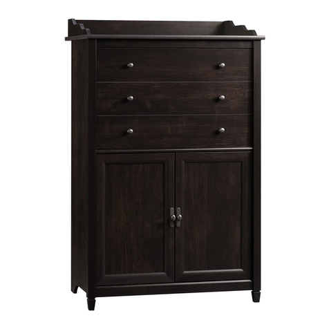
moss DESIGN Caisson Credenza Assembly instructions

moss DESIGN

moss DESIGN Caisson Credenza Assembly instructions

Aquaglide FULL DECK 15.0 owner's manual

Aquaglide

Aquaglide FULL DECK 15.0 owner's manual

AREBOS AR-HE-SW30 user manual

AREBOS

AREBOS AR-HE-SW30 user manual

Till-Hilft Fulda 87005.330 Assembly instructions

Till-Hilft

Till-Hilft Fulda 87005.330 Assembly instructions

Twoey Outside 2010 quick start guide

Twoey Outside

Twoey Outside 2010 quick start guide

Hettich Easys 200 operating instructions

Hettich

Hettich Easys 200 operating instructions

The bedboss RELAX 404 Series owner's manual

The bedboss

The bedboss RELAX 404 Series owner's manual

Oeseder Möbelindustrie Bern 991 720 Assembly instructions

Oeseder Möbelindustrie

Oeseder Möbelindustrie Bern 991 720 Assembly instructions

Costway HW68469 user manual

Costway

Costway HW68469 user manual

Next ALIX A27743 Assembly instructions

Next

Next ALIX A27743 Assembly instructions

BROSA Hans Assembly guide

BROSA

BROSA Hans Assembly guide

Prodigg MINIKA PBA015T-FUR installation manual

Prodigg

Prodigg MINIKA PBA015T-FUR installation manual

manuals.online logo
manuals.online logoBrands
  • About & Mission
  • Contact us
  • Privacy Policy
  • Terms and Conditions

Copyright 2025 Manuals.Online. All Rights Reserved.