manuals.online logo
Brands
  1. Home
  2. •
  3. Brands
  4. •
  5. Sauder
  6. •
  7. Indoor Furnishing
  8. •
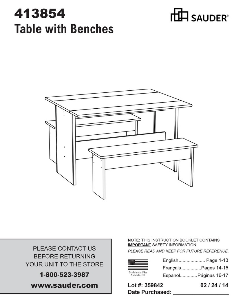
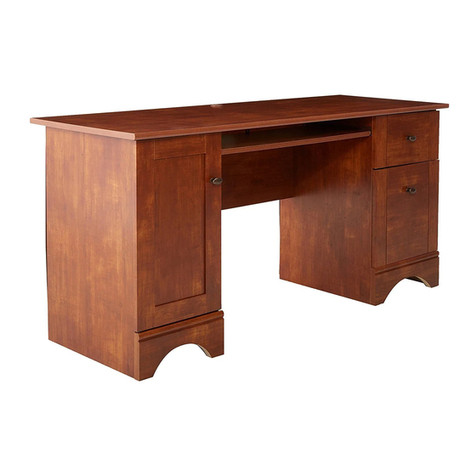
  9. Sauder Carson Forge 415572 User manual

Sauder Carson Forge 415572 User manual

Need help? Visit Sauder.com to view video assembly tips or chat with a live rep.
Prefer the phone? Call 1-800-523-3987.
Share your journey!
sauder.com
NOTE: THIS INSTRUCTION
BOOKLET CONTAINS IMPORTANT
SAFETY INFORMATION.
PLEASE READ AND KEEP FOR
FUTURE REFERENCE.
Enlish p 1-28
Français p 29-32
Español p 33-36
Lot # 387319 01/21/16
Purchased: __________________
Be sure to ive us a rin before
makin any returns. 1-800-523-3987
Credenza
Carson Fore Collection | 415572
Entertaining what
entertains you.
Table of Contents Assembly Tools Required
Part Identification
Hardware Identification
Assembly Steps
Français
Español
Safety
Warranty
Hammer
Not actual size
No. 2 Phillips Screwdriver
Tip Shown Actual Size
Skip the power trip.
This time.
3-4
5-6
7-28
29-32
33-36
37-38
39
WARNING
!
Use of a TV that is too heavy or lare is hazardous. A TV that is too heavy will create a risk of a tip-over that can cause severe injury or
death. A TV that is too lare for the available space miht be accidentally pushed or bumped o the furniture, or subject to tip-over.
• Check the size and weiht of your TV. Compare it to the diaram below – before you begin assembly!
• This Sauder unit is desined for use with televisions weihin less than 135 pounds. Never use with a TV that weihs more.
• The size of the television, front-to-back and side-to-side, must fit within the space defined in the diaram.
• Never place the front ede of the TV past the front ede of the TV support shelf (or stop moldin – if equipped)
• Never allow the sides of the TV to extend past the side edes of the TV support surface.
• If the TV has a CRT picture tube, the picture tube cone may extend past the rear of the support shelf.
• Be sure to apply the warnin label as instructed in the last assembly step. The label provides important safety related information.
72-1/2"
23"
135 lbs.
415572 www.sauder.com/servicesPae 2
Part Identification
åWhile not all parts are labeled, some of the parts will have a label or an inked letter on the ede
to help distinuish similar parts from each other. Use this part identification to help identify similar parts.
Now you know
our ABCs.
A RIGHT END (1)
B LEFT END (1)
C RIGHT UPRIGHT (1)
D LEFT UPRIGHT (1)
E TOP (1)
F BOTTOM (1)
G LARGE BACK (1)
H SMALL BACK (2)
M CENTER ADJUSTABLE SHELF (2)
N ADJUSTABLE SHELF (2)
O BACK SKIRT (1)
P SKIRT (1)
Q RIGHT SKIRT (1)
R LEFT SKIRT (1)
V FRONT MOLDING (1)
W RIGHT MOLDING (1)
X LEFT MOLDING (1)
Y MOLDING (1)
Z BACK MOLDING (2)
AA RIGHT END MOLDING (1)
BB LEFT END MOLDING (1)
CC END MOLDING (4)
DD SHELF MOLDING (2)
EE CENTER SHELF MOLDING (2)
FF SUPPORT FOOT (4)
415572www.sauder.com/services Pae 3
A
B
D
E
F
H
N
Z
H
M
N
C
AA
CC
W
G
XY
CC
Z
CC
DD
P
Q
R
O
EE
EE
M
V
DD
BB
CC
FF
Part Identification
åWhile not all parts are labeled, some of the parts will have a label or an inked letter on the ede
to help distinuish similar parts from each other. Use this part identification to help identify similar parts.
I DRAWER BRACE (1)
J MIDDLE DOOR (1)
K GLASS DOOR (1)
L OUTER DOOR (2)
S RIGHT DRAWER FRONT (1)
T LEFT DRAWER FRONT (1)
U CENTER DRAWER FRONT (1)
D20 RIGHT DRAWER SIDE (3)
D21 LEFT DRAWER SIDE (3)
D63 DRAWER BACK (2)
D169 MIDDLE DRAWER BACK (1)
D733 MIDDLE DRAWER BOTTOM (1)
D968 DRAWER BOTTOM (2)
415572 www.sauder.com/servicesPae 4
I
J
L
D169
L
D733
D968
D968
S
T
U
K
D20
D20
D20
D21
D21
D21
D63
D63
Hardware Identification
åScrews are shown actual size. You may receive extra hardware with your unit.
415572www.sauder.com/services Pae 5
SLIDE CAM - 6
10A
MOLDING CONNECTOR - 2
17F
CAM DOWEL - 17
2F
HIDDEN CAM - 17
1F METAL BRACKET - 10
4G
5E CORNER
CAP - 2 6E FOOT BRACKET - 2 8E CORNER ACCENT - 2
40CB CABINET LEFT - 3
40CA CABINET RIGHT - 3 40CC DRAWER RIGHT - 3 40CD DRAWER LEFT - 3
NAIL - 66
1N
KNOB - 3
52K
METAL PIN - 16
1R
14H CURVED HINGE - 4 DOOR STOP - 3
4I
CAM COVER - 8
12P
PULL - 3
53K
40H HINGE - 2CORNER BRACKET - 4
31G
WARNING
Never use this furniture with a TV that is too
large or too heavy. Severe injury or death
can occur.The TV and furniture will be
unstable and may tip.
-The TV must less than 135 lbs.
-The base of the TV must be able to sit
completely on this shelf.
-Refer to instruction book for complete safety
information.
Note: This is a permanent label. Do not try
to remove. Surface will be damaged.
02/ 02 2 6 9 2 3 2 269232
WARNING LABEL - 1
4L
(Refer to step 20 for proper
location and application)
RUBBER SLEEVE - 16
2R
3M ANTI-SKID PAD - 1
Hardware Identification
åScrews are shown actual size. You may receive extra hardware with your unit.
415572 www.sauder.com/servicesPae 6
SILVER 5/8" MACHINE SCREW - 8
15S BLACK 1-1/8" MACHINE SCREW - 3
21S
GOLD 5/16" FLAT HEAD SCREW - 24
3S BLACK 1-1/4" FLAT HEAD SCREW - 8
7S
BROWN 1" FLAT HEAD SCREW - 8
12S
BLACK 1/2" FLAT HEAD SCREW - 12
11S
BLACK 9/16" LARGE HEAD SCREW - 50
1S BLACK 1-7/8" FLAT HEAD SCREW - 8
2S
30S BLACK 1-9/16" FLAT HEAD SCREW - 13
Step 1 Look for this icon. It means a
video assembly tip is available at
www.sauder.com/services/tips
å Assemble your unit on a carpeted floor or on the empty
carton to avoid scratchin your unit or the floor.
å Push seventeen HIDDEN CAMS (1F) into the ENDS (A
and B), UPRIGHTS (C and D) and DRAWER BRACE (I).
Then, insert the metal end of a CAM DOWEL (2F) into
each HIDDEN CAM.
415572www.sauder.com/services Pae 7
A
B
C
D
I
Arrow
1F
2F
Arrow
1F
2F
1F
2F
Arrow
(17 used)
Do not tihten the HIDDEN CAMS in this step.
Insert the metal end of the CAM
DOWEL into the HIDDEN CAM.
Arrow
Some assembly
(and snacks) required.
å Tap two MOLDING CONNECTORS (17F) into the notches
in the MOLDINGS (W, X, and V).
Step 2
415572 www.sauder.com/servicesPae 8
X
V
W
17F
17F
Flat end
Use your hammer to tap the MOLDING CONNECTORS (17F) into the notches in the MOLDINGS.
Flat end
å Fasten the MOLDINGS (W, X, and V) to the TOP (E). Use
eiht BLACK 1-1/4" FLAT HEAD SCREWS (7S).
Step 3
415572www.sauder.com/services Pae 9
E
Surface with holes
W
X
V
Finished surface
Rounded ede
BLACK 1-1/4" FLAT HEAD SCREW
(8 used in this step)
7S
å Fasten the CABINET RIGHT (40CA) and CABINET
LEFT (40CB) to the ENDS (A and B). Use four GOLD
5/16" FLAT HEAD SCREWS (3S) throuh holes #1 and #3.
Step 4
415572 www.sauder.com/servicesPae 10
A
B
Surface with
HIDDEN CAMS
Surface with
HIDDEN CAMS
GOLD 5/16" FLAT HEAD SCREW
(4 used in this step)
3S
1
2
3
4
1
2
34
Roller end
Roller end
Ede with
HIDDEN CAMS
å Fasten two CABINET RIGHTS (40CA) and two CABINET
LEFTS (40CB) to the UPRIGHTS (C and D). Use eiht
GOLD 5/16" FLAT HEAD SCREWS (3S) throuh holes #1
and #3.
Step 5
415572www.sauder.com/services Pae 11
C
D
Surface with
HIDDEN CAMS
Surface with
HIDDEN CAMS
Roller end
1
2
3
4
3
4
GOLD 5/16" FLAT HEAD SCREW
(8 used in this step)
3S
Finished ede
1
2
34
Roller end
1
2
3
Finished edeRoller end
å Fasten the ACCENT CORNERS (8E) to the END MOLDINGS (AA and BB). Use two SILVER 5/8" MACHINE SCREWS (15S).
å Fasten the MOLDINGS (Z, AA, and BB) to the ENDS (A and B). Tihten eiht HIDDEN CAMS.
Step 6
415572 www.sauder.com/servicesPae 12
Start Tighten
Arrow
Minimum
190 derees
Caution
Risk of damae or
injury. HIDDEN CAMS
must be completely
tihtened. HIDDEN
CAMS that are not
completely tihtened
may loosen, and parts
may separate. To
completely tihten:
Arrow
Maximum
210 derees
Surface with
HIDDEN CAMS Surface with
HIDDEN CAMS
Z
BB
Z
AA
A
B
8E
AA
BB
SILVER 5/8" MACHINE SCREW
(2 used for the PULLS)
15S
These surfaces
should be even.
These surfaces
should be even.
These surfaces
should be even.
Surface with
CORNER ACCENT
Surface with
CORNER ACCENT
å Fasten the ENDS (A and B) to the MOLDINGS (W and X)
on the TOP (E). Tihten four HIDDEN CAMS.
å Fasten the UPRIGHTS (C and D) to the TOP (E). Tihten
four HIDDEN CAMS.
Step 7
415572www.sauder.com/services Pae 13
A
B
C
D
E
Surface with
HIDDEN CAMS
Surface without
HIDDEN CAMS
Surface with
HIDDEN CAMS
Surface without
HIDDEN CAMS
BB
AA
Surface with holes
X
W
Arrow
Minimum
190 derees
Maximum
210 derees
Do not stand the unit upriht without the
BACK fastened. The unit may collapse.
Caution
Finished ede
å Fasten the BOTTOM (F) to the ENDS (A and B) and
UPRIGHTS (C and D). Use eiht BLACK 1-7/8" FLAT
HEAD SCREWS (2S).
å Fasten the END MOLDINGS (CC) to the ENDS (A and B).
Use eiht BROWN 1" FLAT HEAD SCREWS (12S).
Step 8
415572 www.sauder.com/servicesPae 14
A
B
C
D
F
CC
CC
CC
CC
Surface with more holes
Rounded ede
BLACK 1-7/8" FLAT HEAD SCREW
(8 used for the BOTTOM)
2S
BROWN 1" FLAT HEAD SCREW
(8 used for the END MOLDINGS)
12S
å Fasten four METAL BRACKETS (4G) to the ENDS (A
and B) and UPRIGHTS (C and D). Use four BLACK 9/16"
LARGE HEAD SCREWS (1S).
å Fasten the MOLDING (Y) to the ENDS (A and B) and
UPRIGHTS (C and D). Use four BLACK 9/16" LARGE
HEAD SCREWS (1S) throuh the METAL BRACKETS and
into the MOLDING.
å Insert two DOOR STOPS (4I) into the holes in the
UPRIGHTS (C and D).
Step 9
415572www.sauder.com/services Pae 15
4G
Y
4G
4I
A
B
C
D
BLACK 9/16" LARGE HEAD SCREW
(8 used in this step)
1S
(4 used)
(2 used)
Rounded ede
Don't worry. It isn't
Rome. This can be built
in a day.
å Fasten six METAL BRACKETS (4G) to the SKIRT (P) and
BACK SKIRT (O). Use six BLACK 9/16" LARGE HEAD
SCREWS (1S).
å Fasten four CORNER BRACKETS (31G) to the SKIRTS (O
and P). Use eiht BLACK 9/16" LARGE HEAD SCREWS (1S).
Step 10
415572 www.sauder.com/servicesPae 16
O
P
31G
31G
BLACK 9/16" LARGE HEAD SCREW
(14 used in this step)
1S
(6 used)
4G
å Fasten the SKIRTS (O and P) to the BOTTOM (F). Use
fourteen BLACK 9/16" LARGE HEAD SCREWS (1S)
throuh the BRACKETS and into the BOTTOM.
å Fasten the RIGHT SKIRT (Q) and LEFT SKIRT (R) to the
SKIRTS (O and P). Use eiht BLACK 9/16" LARGE HEAD
SCREWS (1S) throuh the CORNER BRACKETS and into
the RIGHT SKIRT (Q) and LEFT SKIRT (R).
Step 11
415572www.sauder.com/services Pae 17
O
P
Q
R
F
BLACK 9/16" LARGE HEAD SCREW
(22 used in this step)
1S
å Carefully turn the unit over onto its front edes. Unfold the LARGE BACK (G). Lay the LARGE BACK (G) and the SMALL
BACKS (H) over the unit. Nail the BACKS (G and H) to the unit alon the edes of the TOP (E), BOTTOM (F), ENDS (A
and B) and UPRIGHTS (C and D). Use sixty-six NAILS (1N).
å NOTE: Be sure to tap the NAILS (1N) into the holes that line up over the UPRIGHTS (C and D).
å NOTE: The backs will overlap each other alon the edes of the UPRIGHTS (C and D).
å NOTE: Perforations have been provided for access throuh the BACKS (G and H). Carefully cut out the holes needed.
å Fasten the FOOT BRACKETS (6E) to the BOTTOM (F). Use six BLACK 9/16" LARGE HEAD SCREWS (1S).
å Slide the SUPPORT FEET (FF) onto the FOOT BRACKETS (6E).
å Firmly push the CORNER CAPS (5E) onto the SUPPORT FEET (FF).
Step 12
415572 www.sauder.com/servicesPae 18
Do not stand the unit upriht without the
BACK fastened. The unit may collapse.
Caution
G
H
H
A
B
E
F
6E
6E
FF
FF
5E
5E
Unfinished
surface
6E
BLACK 9/16" LARGE HEAD SCREW
(6 used for the FOOT BRACKETS)
1S
NAIL
(66 used in this step)
1N
These holes must line
up over the UPRIGHTS.
These perforated
holes must be here.
å NOTE: You have the option of fastenin the MIDDLE
DOOR (J) or the GLASS DOOR (K) to the center of the
unit. Also, the door can open either to the riht or the left.
The followin steps will show the GLASS DOOR (K) bein
fastened to the unit.
Step 13
415572www.sauder.com/services Pae 19
J
K
Openin to the left
Openin to the riht
MIDDLE DOOR
GLASS DOOR
å Fasten the HINGES (40H) to the MIDDLE DOOR (J) or
GLASS DOOR (K). Use four BLACK 1/2" FLAT HEAD
SCREWS (11S).
Step 14
415572 www.sauder.com/servicesPae 20
J
K
40H
40H
BLACK 1/2" FLAT HEAD SCREW
(4 used in this step)
11S

Other Sauder Indoor Furnishing manuals

Sauder 416091 User manual

Sauder

Sauder 416091 User manual

Sauder Shoal Creek 420166 User manual

Sauder

Sauder Shoal Creek 420166 User manual

Sauder Costa 419958 User manual

Sauder

Sauder Costa 419958 User manual

Sauder Costa 428724 User manual

Sauder

Sauder Costa 428724 User manual

Sauder Costa 421934 User manual

Sauder

Sauder Costa 421934 User manual

Sauder Edge Water 414856 User manual

Sauder

Sauder Edge Water 414856 User manual

Sauder 409942 User manual

Sauder

Sauder 409942 User manual

Sauder Summer Home Pantry 401867 User manual

Sauder

Sauder Summer Home Pantry 401867 User manual

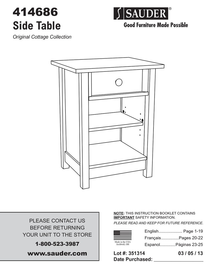
Sauder Worksense MASON PEAK 427835 User manual
Sauder

Sauder Worksense MASON PEAK 427835 User manual

Sauder Armoire 419451 User manual

Sauder

Sauder Armoire 419451 User manual

Sauder North Avenue User manual

Sauder

Sauder North Avenue User manual

Sauder Pinwheel Collection 422600 User manual

Sauder

Sauder Pinwheel Collection 422600 User manual

Sauder 419198 User manual

Sauder

Sauder 419198 User manual

Sauder 425024 User manual

Sauder

Sauder 425024 User manual

Sauder Englewood 426484 User manual

Sauder

Sauder Englewood 426484 User manual

Sauder Manhattan Gate 429257 User manual

Sauder

Sauder Manhattan Gate 429257 User manual

Sauder International Lux 421434 User manual

Sauder

Sauder International Lux 421434 User manual

Sauder Shoal Creek 411201 User manual

Sauder

Sauder Shoal Creek 411201 User manual

Sauder Shoal Creek 409937 User manual

Sauder

Sauder Shoal Creek 409937 User manual

Sauder Carson Forge 412921 User manual

Sauder

Sauder Carson Forge 412921 User manual

Sauder Entertainment Credenza 412922 User manual

Sauder

Sauder Entertainment Credenza 412922 User manual

Sauder OfficeWorks AFFIRM 427424 User manual

Sauder

Sauder OfficeWorks AFFIRM 427424 User manual

Sauder STEADFAST 402932 User manual

Sauder

Sauder STEADFAST 402932 User manual

Sauder Orchard Hills 401292 User manual

Sauder

Sauder Orchard Hills 401292 User manual

Popular Indoor Furnishing manuals by other brands

Hillsdale Furniture NORWOOD 4935-826S quick start guide

Hillsdale Furniture

Hillsdale Furniture NORWOOD 4935-826S quick start guide

Next T29053 Assembly instructions

Next

Next T29053 Assembly instructions

PAIDI Fionn 131 1011 instructions

PAIDI

PAIDI Fionn 131 1011 instructions

Furniture of America FOA7887D-M Assembly instructions

Furniture of America

Furniture of America FOA7887D-M Assembly instructions

dams R1090TC manual

dams

dams R1090TC manual

FMD CHAT 229-001 Assembly guide

FMD

FMD CHAT 229-001 Assembly guide

Habitat Macadam 904536 manual

Habitat

Habitat Macadam 904536 manual

FIAM. GRAPH 2280 manual

FIAM.

FIAM. GRAPH 2280 manual

sidhil 3012/LO user guide

sidhil

sidhil 3012/LO user guide

SEI Mirage CM915700TX Assembly instructions

SEI

SEI Mirage CM915700TX Assembly instructions

Takara Belmont W SWING YUME operating instructions

Takara Belmont

Takara Belmont W SWING YUME operating instructions

Home Decorators Collection COLTON 760-100 Use and care guide

Home Decorators Collection

Home Decorators Collection COLTON 760-100 Use and care guide

Studio Designs HOME CORBEL 74000 Assembly instructions

Studio Designs

Studio Designs HOME CORBEL 74000 Assembly instructions

FMD Möbel Sideboard Assembly instruction

FMD Möbel

FMD Möbel Sideboard Assembly instruction

Glideware Not-So-Lazy Susan installation instructions

Glideware

Glideware Not-So-Lazy Susan installation instructions

Pineapple RYNO CHAIR Assembly instructions

Pineapple

Pineapple RYNO CHAIR Assembly instructions

Home Decorators 24 in. Base Cabinet installation guide

Home Decorators

Home Decorators 24 in. Base Cabinet installation guide

VIPACK AMORI AMHB9014 Assembly instructions

VIPACK

VIPACK AMORI AMHB9014 Assembly instructions

manuals.online logo
manuals.online logoBrands
  • About & Mission
  • Contact us
  • Privacy Policy
  • Terms and Conditions

Copyright 2025 Manuals.Online. All Rights Reserved.