manuals.online logo
Brands
  1. Home
  2. •
  3. Brands
  4. •
  5. Sauder
  6. •
  7. Indoor Furnishing
  8. •
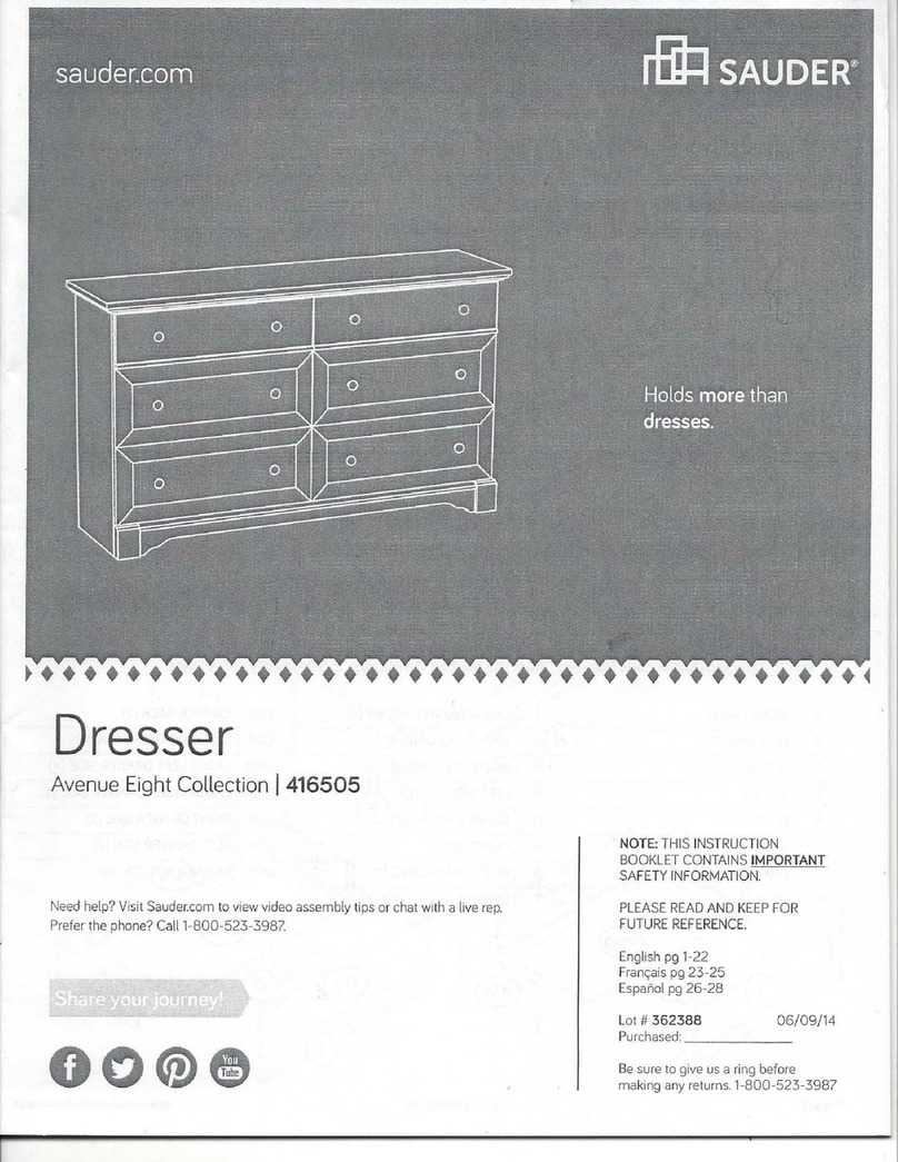
  9. Sauder Edge Water 418796 User manual

Sauder Edge Water 418796 User manual

NOTE: THIS INSTRUCTION
BOOKLET CONTAINS IMPORTANT
SAFETY INFORMATION.
PLEASE READ AND KEEP FOR
FUTURE REFERENCE.
English pg 1-22
Français pg 23-25
Español pg 26-28
Lot # 385950 10/26/15
Purchased: __________________
Be sure to give us a ring before
making any returns. 1-800-523-3987
Lateral File
Edge Water Collection | Model 418796
Need help? Visit Sauder.com to view video assembly tips or chat with a live rep.
Prefer the phone? Call 1-800-523-3987.
Share your journey!
sauder.com
Get all organized
and stu.
Table of Contents Assembly Tools Required
2-3
4-5
6-22
23-25
26-28
29-30
31
Part Identification
Hardware Identification
Assembly Steps
Français
Español
Safety
Warranty
Hammer
Not actual size
No. 2 Phillips Screwdriver
Tip Shown Actual Size
418796 www.sauder.com/servicesPage 2
Part Identification
åWhile not all parts are labeled, some of the parts will have a label or an inked letter on the edge
to help distinguish similar parts from each other. Use this part identification to help identify similar parts.
A RIGHT END (1)
B LEFT END (1)
C TOP (1)
D BOTTOM (1)
E BACK (1)
F2 LEG (2)
G DRAWER FRONT (2)
K BOTTOM MOLDING (1)
L FOOT (2)
D225 DRAWER SIDE (4)
D243 DRAWER BOX FRONT (4)
D928 DRAWER BOTTOM (2)
Part Identification
418796www.sauder.com/services Page 3
A
B
C
D
E
F2
G
F2
G
KL
L
D225
D225
D225
D225
D243
D243
D243
D243
D928
D928
Hardware Identification
åScrews are shown actual size. You may receive extra hardware with your unit.
(EXTENSION SET SHOWN SEPARATED)
EXTENSION RAIL - 4
MEXTENSION SLIDE - 4
N
FILE GLIDE - 4
5B
20G DRAWER STOP - 2
FILE BRACKET - 4
11B
FILE BAR - 4
1B FILE ROD - 4
9B
INTERLOCK TRACK - 1
22G
HIDDEN CAM - 18
1F CAM DOWEL - 12
2F CAM SCREW - 6
8F
418796 www.sauder.com/servicesPage 4
29G SAFETY STOP - 2 124K KNOB - 4
METAL BRACKET - 3
4G
Hardware Identification
åScrews are shown actual size. You may receive extra hardware with your unit.
BLACK 1-1/4" FLAT HEAD SCREW - 16
7S
BLACK 1-1/8" MACHINE SCREW - 4
21S
BLACK 7/8" LARGE HEAD SCREW - 8
17S
BLACK 9/16" LARGE HEAD SCREW - 6
1S
BROWN 7/16" LARGE HEAD SCREW - 8
6S
3S GOLD 5/16" FLAT HEAD SCREW - 16
418796www.sauder.com/services Page 5
16S BLACK 1-7/8" PAN HEAD SCREW - 2
Step 1 Look for this icon. It means a
video assembly tip is available at
www.sauder.com/services/tips
å Assemble your unit on a carpeted floor or on the empty
carton to avoid scratching your unit or the floor.
å Push eighteen HIDDEN CAMS (1F) into the
ENDS (A and B), BOTTOM (D), and BACK (E). Then, insert
the metal end of a CAM DOWEL (2F) into each HIDDEN
CAM, except in the long edge of the ENDS.
418796 www.sauder.com/servicesPage 6
Do not tighten the HIDDEN CAMS in this step.
(18 used)
(12 used)
Arrow
1F
2F
Insert the metal end of the CAM
DOWEL into the HIDDEN CAM.
Arrow
Arrow
Arrow
1F
The arrow in the HIDDEN
CAM must point toward the
hole in the edge of the board.
Hole
Do not insert CAM
DOWELS into this edge.
A
B
D
E
Do not insert CAM
DOWELS into this edge.
Scan this QR code or go to this address:
http://qr.sauder.com/?ID=1460
to watch a video on how to assemble your unit.
StepStep 2
å Insert two SAFETY STOPS (29G) into the holes shown in
the RIGHT END (A).
418796www.sauder.com/services Page 7
A
29G
This pin must insert
into the location holes
in the RIGHT END (A).
29G
Step 3
å Diagram 1. Cut out and use the "spacer" at the top of this page to measure 2-1/2" from one end of the
INTERLOCK TRACK (22G). Position the INTERLOCK TRACK as shown.
å ACTUATOR / TRACK ATTACHMENT:
å Diagram 2. Tilt the first edge of the INTERLOCK TRACK (22G) into the SAFETY STOP (29G).
å Diagram 3. Rotate the INTERLOCK TRACK and apply force to engage the second edge into the
SAFETY STOP.
å Diagram 4. Repeat the SAFETY STOP / TRACK ATTACHMENT for the next SAFETY STOP while
holding the previously completed SAFETY STOP in its location hole. Repeat these steps until all SAFETY
STOPS have been attached.
å Visually check that all INTERLOCK TRACK edges have been engaged into the SAFETY STOP as shown
in diagram 3. Then, remove the INTERLOCK TRACK assembly from the END.
418796 www.sauder.com/servicesPage 8
A
1.
4.
3.2.
Cut out this rectangle to use as a "spacer"
2-1/2"
2-1/2"
22G 22G
29G
29G
29G
22G
29G
Surface with
HIDDEN CAMS
Do not slide the CABINET ACTUATORS
onto the INTERLOCK TRACK.
22G
å Turn six CAM SCREWS (8F) into the LEGS (F2).
å Fasten the LEGS (F2) to the ENDS (A and B). Tighten six
hidden cams.
å Fasten the FEET (L) to the LEGS (F2). Use two BLACK
1-7/8" PAN HEAD SCREWS (16S).
Step 4
418796www.sauder.com/services Page 9
A
B
L
F2
F2
F2
F2
L
12
8F
(6 used)
These surfaces must be even.
Surface with
HIDDEN CAMS
Surface with
HIDDEN CAMS
BLACK 1-7/8" PAN HEAD SCREW
(2 used in this step)
16S
View after the FOOT is fastened
Step 5
å Insert the INTERLOCK TRACK (22G) with SAFETY STOPS (29G) into
the groove in the RIGHT END (A) exactly as shown.
å Separate the EXTENSION SLIDES (N) from the EXTENSION RAILS (M)
as shown in the upper diagram below. Be prepared, the parts are greasy.
å Fasten two EXTENSION RAILS (M) to each END (A and B). Use eight
GOLD 5/16" FLAT HEAD SCREWS (3S).
å NOTE: For each EXTENSION RAIL, turn a SCREW into the hole
shown in the enlarged diagram. Then, slide the inner cartridge of the
EXTENSION RAIL out to find the other hole that lines up with the hole in
the END. Turn a SCREW into this hole.
418796 www.sauder.com/servicesPage 10
A
M
B
M
M
M
M
N
GOLD 5/16" FLAT HEAD SCREW
(8 used in this step)
3S
Hole
Open end
Open end
29G
22G
Push the black lever in and pull the SLIDE from the RAIL.
After fastening the RAILS to the ENDS, rest
the INTERLOCK TRACK assembly against the
RAILS. There should be no more than a 1/16"
gap between all ACTUATORS and RAILS.
Remember:
Righty tighty.
Lefty loosey.
å Fasten the LEFT END (B) to the BACK (E). Tighten two
HIDDEN CAMS.
Step 6
418796www.sauder.com/services Page 11
B
E
Surface with HIDDEN CAMS
These edges must be even.
Start Tighten
Arrow
Minimum
190 degrees
Caution
Risk of damage or
injury. HIDDEN CAMS
must be completely
tightened. HIDDEN
CAMS that are not
completely tightened
may loosen, and parts
may separate. To
completely tighten:
Arrow
Maximum
210 degrees
F2
Surface
with
HIDDEN
CAMS
Step 7
å Fasten the BOTTOM (D) to the LEFT END (B). Tighten two
HIDDEN CAMS.
å Fasten the RIGHT END (A) to the BOTTOM (D) and
BACK (E). Tighten four HIDDEN CAMS.
418796 www.sauder.com/servicesPage 12
A
E
D
Surface with HIDDEN CAMS
Arrow
Minimum
190 degrees
Maximum
210 degrees
B
Surface without
HIDDEN CAMS
These holes must be here.
å Fasten three METAL BRACKETS (4G) to the BOTTOM (D).
Use three BLACK 9/16" LARGE HEAD SCREWS (1S).
å NOTE: Be sure the BRACKETS are even with the edges of
the BOTTOM.
å Fasten the BOTTOM MOLDING (K) to the METAL
BRACKETS (4G). Use three BLACK 9/16" LARGE
HEAD SCREWS (1S).
Step 8
418796www.sauder.com/services Page 13
D
K
BLACK 9/16" LARGE HEAD SCREW
(6 used in this step)
1S
Curved edge
4G
Step 9
å Carefully stand your unit upright.
å Fasten the TOP (C) to the ENDS (A and B). Tighten four
HIDDEN CAMS.
418796 www.sauder.com/servicesPage 14
A
C
Arrow
Minimum
190 degrees
Maximum
210 degrees
B
Finished surface
Rounded edge
Pro Tip: Lift with your
legs. And, you know,
your arms.
å Fasten two DRAWER SIDES (D225) to one of the
DRAWER BOX FRONTS (D243). Use four BLACK 1-1/4"
FLAT HEAD SCREWS (7S).
å Repeat this step for the other drawer.
Step 10
418796www.sauder.com/services Page 15
D225
D225
D243
BLACK 1-1/4" FLAT HEAD SCREW
(8 used in this step)
7S
Be sure the grooves in each
part line up with each other
on the inside of the drawer.
Step 11
å Slide a DRAWER BOTTOM (D928) into the grooves in the
DRAWER SIDES (D225).
å Fasten a DRAWER BOX FRONT (D243) to the DRAWER
SIDES (D225). Use four BLACK 1-1/4" FLAT
HEAD SCREWS (7S).
å Repeat this step for the other drawer.
418796 www.sauder.com/servicesPage 16
D225
D225
D243
D243
D928
BLACK 1-1/4" FLAT HEAD SCREW
(8 used in this step)
7S
Finished surface
å Fasten a DRAWER FRONT (G) to one of the DRAWER
BOX FRONTS (D243). Use four BLACK 7/8" LARGE
HEAD SCREWS (17S).
å Fasten two KNOBS (124K) to the DRAWER FRONT (G).
Use two BLACK 1-1/8" MACHINE SCREW (21S).
å NOTE: The hole on back surface of the DRAWER FRONT
must be close to the bottom edge.
å Repeat this step for the other drawer.
Step 12
418796www.sauder.com/services Page 17
G
D243
BLACK 7/8" LARGE HEAD SCREW
(8 used for the DRAWER FRONTS)
17S
BLACK 1-1/8" MACHINE SCREW
(4 used for the KNOBS)
21S
The hole on the opposite surface
must be close to the bottom edge.
124K
Step 13
å Stand one of the drawers upright onto the RIGHT
DRAWER SIDE (D225).
å Fasten one of the EXTENSION SLIDES (N) through holes
#2 and #4 to the LEFT DRAWER SIDE (D225). Use two
GOLD 5/16" FLAT HEAD SCREWS (3S).
418796 www.sauder.com/servicesPage 18
D225
D225
N
1
2
34
GOLD 5/16" FLAT HEAD SCREW
(4 used in this step)
3S
Open end
2.
å Flip the drawer over onto the left DRAWER SIDE (D225).
å Diagram 1. Insert the tabs on a DRAWER STOP (20G) into the
slots in a EXTENSION SLIDE (N). You may need to insert one
tab first, then the other.
å Diagram 2. Visually check that the DRAWER STOP (20G) is
seated in the EXTENSION SLIDE (N).
å Diagram 3. If the DRAWER STOP is not seated, use your
hammer to gently tap the SLIDE until the tabs are properly
seated in the slots.
å Now, fasten this EXTENSION SLIDE (N) to the right DRAWER
SIDE (D225). Use two GOLD 5/16" FLAT HEAD SCREWS (3S).
å Repeat steps 13 and 14 for the other drawer.
Step 14
418796www.sauder.com/services Page 19
GOLD 5/16" FLAT HEAD SCREW
(4 used in this step)
3S
D225
D225
N
D225
20G
N
3.
1.
Open end
20G
20G
Seated
Post
Slots
These tabs must
insert into the slots.
Step
å Fasten two FILE BRACKETS (11B) to the DRAWER BOX
FRONTS (D243). Use four BROWN 7/16" LARGE
HEAD SCREWS (6S).
å Repeat this step for the other drawer.
Step 15
418796 www.sauder.com/servicesPage 20
11B
D243
11B
BROWN 7/16" LARGE HEAD SCREW
(8 used in this step)
6S

Other Sauder Indoor Furnishing manuals

Sauder SmartCenter Edge Water 413092 User manual

Sauder

Sauder SmartCenter Edge Water 413092 User manual

Sauder Adept 418085 User manual

Sauder

Sauder Adept 418085 User manual

Sauder Center City 425653 User manual

Sauder

Sauder Center City 425653 User manual

Sauder Via 419708 User manual

Sauder

Sauder Via 419708 User manual

Sauder Costa 428724 User manual

Sauder

Sauder Costa 428724 User manual

Sauder Orchard Hills 418651 User manual

Sauder

Sauder Orchard Hills 418651 User manual

Sauder Heritage Hill Lateral File 102702 User manual

Sauder

Sauder Heritage Hill Lateral File 102702 User manual

Sauder OfficeWorks AFFIRM 426279 User manual

Sauder

Sauder OfficeWorks AFFIRM 426279 User manual

Sauder OFFICE WORKS AFFIRM 427868 User manual

Sauder

Sauder OFFICE WORKS AFFIRM 427868 User manual

Sauder Harbor View 158015 User manual

Sauder

Sauder Harbor View 158015 User manual

Sauder Whitaker Point 429369 User manual

Sauder

Sauder Whitaker Point 429369 User manual

Sauder Barrister Lane 416798 User manual

Sauder

Sauder Barrister Lane 416798 User manual

Sauder Clifford Place 429501 User manual

Sauder

Sauder Clifford Place 429501 User manual

Sauder 414129 User manual

Sauder

Sauder 414129 User manual

Sauder 414724 User manual

Sauder

Sauder 414724 User manual

Sauder Worksense MASON PEAK 427827 User manual

Sauder

Sauder Worksense MASON PEAK 427827 User manual

Sauder Bridge Acre 427324 User manual

Sauder

Sauder Bridge Acre 427324 User manual

Sauder Corner Entertainment Credenza 403818 User manual

Sauder

Sauder Corner Entertainment Credenza 403818 User manual

Sauder 402159 User manual

Sauder

Sauder 402159 User manual

Sauder Pogo 417675 User manual

Sauder

Sauder Pogo 417675 User manual

Sauder Shoal Creek 409733 User manual

Sauder

Sauder Shoal Creek 409733 User manual

Sauder Parklane Series User manual

Sauder

Sauder Parklane Series User manual

Sauder 411312 User manual

Sauder

Sauder 411312 User manual

Sauder Worksense MASON PEAK 427835 User manual

Sauder

Sauder Worksense MASON PEAK 427835 User manual

Popular Indoor Furnishing manuals by other brands

BLACK RED WHITE NFC-713/396 LV/PV Assembly manual

BLACK RED WHITE

BLACK RED WHITE NFC-713/396 LV/PV Assembly manual

Outbound 076-3200 instruction manual

Outbound

Outbound 076-3200 instruction manual

Wellis my line Ginger 60 Series installation guide

Wellis

Wellis my line Ginger 60 Series installation guide

RTA KODIAK RTA-8830 Assembly instruction

RTA

RTA KODIAK RTA-8830 Assembly instruction

BIG FURNITURE WAREHOUSE COLONIAL CORNER WALL SHELF Assembly instructions

BIG FURNITURE WAREHOUSE

BIG FURNITURE WAREHOUSE COLONIAL CORNER WALL SHELF Assembly instructions

Jysk BROBY 3674157 manual

Jysk

Jysk BROBY 3674157 manual

IKEA BOLLSIDAN manual

IKEA

IKEA BOLLSIDAN manual

Home Decorators Collection PPLNKWHT36DM Use and care guide

Home Decorators Collection

Home Decorators Collection PPLNKWHT36DM Use and care guide

Sunnydaze Decor AGR-348 manual

Sunnydaze Decor

Sunnydaze Decor AGR-348 manual

leolux Quantissimo Assembly instructions

leolux

leolux Quantissimo Assembly instructions

Coaster 183437 Assembly instructions

Coaster

Coaster 183437 Assembly instructions

Better Homes and Gardens BH18-084-097-30 manual

Better Homes and Gardens

Better Homes and Gardens BH18-084-097-30 manual

AVF SDC1140 Assembly instructions

AVF

AVF SDC1140 Assembly instructions

Castleton Home DD-KHB8270-1CR manual

Castleton Home

Castleton Home DD-KHB8270-1CR manual

BRW LOFT B156-KOM2D2S/150 Assembly

BRW

BRW LOFT B156-KOM2D2S/150 Assembly

JWA GATES 75266 Assembly instruction

JWA

JWA GATES 75266 Assembly instruction

Coolaroo Easy Release instruction manual

Coolaroo

Coolaroo Easy Release instruction manual

UPC 3637A Assembly instructions

UPC

UPC 3637A Assembly instructions

manuals.online logo
manuals.online logoBrands
  • About & Mission
  • Contact us
  • Privacy Policy
  • Terms and Conditions

Copyright 2025 Manuals.Online. All Rights Reserved.