manuals.online logo
Brands
  1. Home
  2. •
  3. Brands
  4. •
  5. Sauder
  6. •
  7. Indoor Furnishing
  8. •
  9. Sauder Graham Hill 422811 User manual

Sauder Graham Hill 422811 User manual

NOTE: THIS INSTRUCTION
BOOKLET CONTAINS IMPORTANT
SAFETY INFORMATION.
PLEASE READ AND KEEP FOR
FUTURE REFERENCE.
English pg 1-20
Français pg 21-24
Español pg 25-28
Lot # 509676 10/11/17
Purchased: __________________
Be sure to give us a ring before
making any returns. 1-800-523-3987
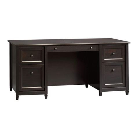
Desk
Graham Hill Collection | Model 422811
Need help? Visit Sauder.com to view video assembly tips or chat with a live rep.
Prefer the phone? Call 1-800-523-3987.
Share your journey!
sauder.com
For all your
newfangled gadgetry.
Table of Contents Assembly Tools Required
2-3
4
5-22
23-25
26-28
29-30
31
Part Identification
Hardware Identification
Assembly Steps
Français
Español
Safety
Warranty
Hammer
Not actual size
No. 2 Phillips Screwdriver
Tip Shown Actual Size
422811 www.sauder.com/servicesPage 2
Part Identification
åWhile not all parts are labeled, some of the parts will have a label or an inked letter on the edge
to help distinguish similar parts from each other. Use this part identification to help identify similar parts.
A RIGHT END (1)
B LEFT END (1)
C2 UPRIGHT (1)
D2 RIGHT UPRIGHT (2)
D14 LARGE RIGHT DRAWER SIDE (1)
D15 LARGE LEFT DRAWER SIDE (1)
D78 LARGE DRAWER BACK (1)
D107 RIGHT DRAWER SIDE (1)
D108 LEFT DRAWER SIDE (1)
D109 DRAWER BACK (1)
D707 LARGE DRAWER BOTTOM (1)
D716 DRAWER BOTTOM (1)
E2 LEFT UPRIGHT (1)
F TOP (1)
G HUTCH TOP (1)
H2 MODESTY PANEL (1)
I SHELF (1)
J HUTCH BACK (1)
K BACK (1)
L BRACE (2)
M SIDE BASE (2)
N BASE (1)
O LARGE DRAWER FRONT (1)
T DRAWER FRONT (1)
Electric drill with 1/4" bit
(ONLY in indicated step)
Part Identification Now you know
our ABCs.
422811www.sauder.com/services Page 3
A
B
C2
D2
E2 F
G
H2
I
J
K
L
M
N
O
T
D2
LM
D107
D109
D707
D108
D78 D14
D15
D716
Hardware Identification
åScrews are shown actual size. You may receive extra hardware with your unit.
422811 www.sauder.com/servicesPage 4
40CA CABINET RIGHT - 1 40CB CABINET LEFT - 1
40CC DRAWER RIGHT - 1 40CD DRAWER LEFT - 1
NAIL - 44
1N
30S BLACK 1-9/16" FLAT HEAD SCREW - 8
(EXTENSION SET SHOWN SEPARATED)
EXTENSION RAIL - 2
35MA EXTENSION SLIDE - 2
35MC
FILE GLIDE - 2
4B
SILVER 3/4" MACHINE SCREW - 1
20S
ANGLE BRACKET - 4
27G
BLACK 9/16" LARGE HEAD SCREW - 8
1S
15S SILVER 5/8" MACHINE SCREW - 1
10F TWIST-LOCK®
FASTENER - 21
12S BROWN 1" FLAT HEAD SCREW - 4
3S GOLD 5/16" FLAT HEAD SCREW - 16
METAL PIN - 4
1R
10A SLIDE CAM - 4
BLACK 1-15/16" FLAT HEAD SCREW - 8
113S
PULL - 2
161K
Step 1 Look for this icon. It means a
video assembly tip is available at
www.sauder.com/services/tips
å Assemble your unit on a carpeted floor or on the empty
carton to avoid scratching your unit or the floor.
å To begin assembly, push twenty-one SAUDER
TWIST-LOCK® FASTENER (10F) into the large holes in the
RIGHT END (A), LEFT END (B), UPRIGHTS (C2, D2, and
E2), MODESTY PANEL (H2), SHELF (I), and BRACES (L).
422811www.sauder.com/services Page 5
(21 used)
10F
10F
10F
Do not tighten the TWIST-LOCK® FASTENERS in this step.
A
B
C2
E2
D2 x 2
Lx 2
H2
I
Step 2
å Separate the EXTENSION SLIDES (35MC) from the EXTENSION RAILS (35MA) as
shown in the upper diagram below. Be prepared, the parts are greasy.
å Fasten the EXTENSION RAILS (35MA) to the LEFT END (B) and UPRIGHT (C2). Use
four GOLD 5/16" FLAT HEAD SCREWS (3S).
å NOTE: For each EXTENSION RAIL, turn a SCREW into the hole shown in the
enlarged diagram. Then, slide the inner cartridge of the EXTENSION RAIL out to find
the other hole that lines up with the hole in the END and UPRIGHT. Turn a SCREW
into this hole.
å NOTE: The EXTENSION SLIDES (35MC) will be used later for the DRAWERS.
å Fasten the CABINET RIGHT (40CA) to the UPRIGHT (C2) and CABINET LEFT (40CB)
to the LEFT END (B). Use four GOLD 5/16" FLAT HEAD SCREWS (3S) through holes
#1 and #3.
422811 www.sauder.com/servicesPage 6
B
Open end
Open end
Remember:
Righty tighty.
Lefty loosey.
Surface with
TWIST-LOCK®
FASTENERS
Surface with
TWIST-LOCK®
FASTENERS
Roller end
Roller end GOLD 5/16" FLAT HEAD SCREW
(8 used in this step)
3S
Push the black lever in and pull the SLIDE from the RAIL.
35MA
35MC
1
2
3
4
1
2
34C2
å Fasten the UPRIGHTS (D2 and E2) to the HUTCH TOP (G).
Tighten three TWIST-LOCK® FASTENERS.
Step 3
422811www.sauder.com/services Page 7
How to use the SAUDER TWIST-LOCK®FASTENER
1. Insert the dowel end of the FASTENER into the hole of the
adjoining part.
NOTE: The dowel end of the FASTENER must remain fully
inserted in the hole of the adjoining part while locking
the FASTENER.
2. Tighten the FASTENER with a Phillips screwdriver as tight
as possible.
Dowel end
G
D2
D2
E2
Curved edge
Unfinished edge
Curved edge
Curved edge
Step 4
å Finish drilling the six holes shown in the bottom surface of
the TOP (F) using a 1/4" or 6.5mm drill bit.
å Next, fasten the TOP (F) to the UPRIGHTS (D2 and E2).
Use six BLACK 1-15/16" FLAT HEAD SCREWS (113S).
F
D2
D2
E2
Unfinished surface
Long rounded edge
Finish drilling the holes from
the bottom surface. Use a
1/4" or 6.5mm drill bit. Then,
use six BLACK 1-15/16" FLAT
HEAD SCREWS (113S).
422811 www.sauder.com/servicesPage 8
BLACK 1-15/16" FLAT HEAD SCREW
(6 used in this step)
113S
å Insert four METAL PINS (1R) into the BRACES (L).
å Fasten the BRACES (L) and SHELF (I) to the LEFT END (B).
Tighten four TWIST-LOCK® FASTENERS.
å NOTE: Be sure the METAL PINS insert into the holes in the
LEFT END.
Step 5
422811www.sauder.com/services Page 9
Curved edge
L
B
Surface with
TWIST-LOCK®
FASTENERS
Surface with
TWIST-LOCK®
FASTENERS
Surface with
TWIST-LOCK®
FASTENERS
These holes
must be here.
These holes
must be here.
1R
1R
Do not stand the unit upright without the
BACK fastened. The unit may collapse.
Caution
L
I
Rounded edge
Step 6
å Fasten the UPRIGHT (C2) to the BRACES (L) and SHELF (I).
Tighten four TWIST-LOCK® FASTENERS.
å NOTE: Be sure the METAL PINS in the BRACES insert
into the UPRIGHT.
C2
L
LI
Surface without TWIST-LOCK® FASTENERS
Curved edge
422811 www.sauder.com/servicesPage 10
Step 7
å Fasten the SIDE BASES (M) to the LEFT END (B)
and UPRIGHT (C2). Use four BROWN 1" FLAT
HEAD SCREWS (12S).
Surface with
TWIST-LOCK®
FASTENERS
C2
B
I
M
M
BROWN 1" FLAT HEAD SCREW
(4 used in this step)
12S
Surface without holes
Long unfinished edge
Curved edge
422811www.sauder.com/services Page 11
Step
å Carefully turn the assembly onto its front edges.
å Fasten four ANGLE BRACKETS (27G) to the LEFT END (B),
UPRIGHT (C2), and BRACE (L). Use four BLACK 9/16" LARGE
HEAD SCREWS (1S).
å NOTE: Be sure the edges of the ANGLE BRACKETS are even
with the edges of the END, UPRIGHT, and BRACE.
å Fasten the BASE (N) to the LEFT END (B), UPRIGHT (C2), and
BRACE (L). Use four BLACK 9/16" LARGE HEAD SCREWS (1S).
Step 8
C2
B
L
N
BLACK 9/16" LARGE HEAD SCREW
(8 used in this step)
1S
27G
27G
27G
(4 used)
422811 www.sauder.com/servicesPage 12
StepStep 9
å You will need someone’s help in this step.
å Carefully stand the assembly upright.
å Fasten the RIGHT END (A) to the MODESTY PANEL (H2).
Tighten two TWIST-LOCK® FASTENERS.
å NOTE: Be sure to support the MODESTY PANEL until it is
fastened to the UPRIGHT (C2).
å Fasten the MODESTY PANEL (H2) to the UPRIGHT (C2).
Use two BLACK 1-15/16" FLAT HEAD SCREWS (113S).
Pro Tip: Lift with your
legs. And, you know,
your arms.
Surface without
TWIST-LOCK®
FASTENERS
C2
H2
A
Edge with TWIST-LOCK® FASTENERS
Curved edge
BLACK 1-15/16" FLAT HEAD SCREW
(2 used in this step)
113S
422811www.sauder.com/services Page 13
Surface with
TWIST-LOCK®
FASTENERS
Step
å You will need someone’s help in this step.
å Fasten the TOP (F) to the ENDS (A and B),
UPRIGHT (C2), and MODESTY PANEL (H2).
Tighten eight TWIST-LOCK® FASTENERS.
Step 10
A
F
C2
H2
B
Long rounded edge
422811 www.sauder.com/servicesPage 14
StepStep 11
å Carefully turn your unit over onto its front edges. Lay the
BACKS (J and K) over your unit.
å Make equal margins along all four edges of the BACKS (J and K).
å Fasten the BACKS (J and K) to your unit using the NAILS (1N).
å NOTE: Be sure to tap NAILS into the holes that line up over
the UPRIGHT (D2).
å NOTE: Perforations have been provided for access through
the BACK. Carefully cut out the holes needed.
Do not stand the unit upright without the
BACK fastened. The unit may collapse.
Caution
Unfinished surface
These holes must line up
over the UPRIGHT (D2).
NAIL
(44 used in this step)
1N
Unfinished
surface
Cut-out
J
K
422811www.sauder.com/services Page 15
StepStep 12 VIEW THE T-LOCK BOX VIDEO
å Fasten the LARGE DRAWER BACK (D78) to the LARGE DRAWER
SIDES (D14 and D15). Use four BLACK 1-9/16" FLAT HEAD SCREWS (30S).
å NOTE: Be sure the DRAWER BOTTOM (D716) inserts into the groove of the LARGE DRAWER BACK (D78).
12
3
å Insert the LARGE DRAWER SIDES (D14 and D15)
at an angle into the slot at each end of the LARGE
DRAWER FRONT (O).
å Slide the DRAWER BOTTOM (D716) into the grooves in
the LARGE DRAWER SIDES (D14 and D15) and LARGE
DRAWER FRONT (O).
The tabs should insert freely
into the slots. Gently tilt the
DRAWER SIDES side to side
until the tabs slip into the slots.
Groove
Be sure the DRAWER
BOTTOM inserts into the
DRAWER FRONT groove.
D14
D15
D716
D716
D14
D15
D78
D15
O
O
Unfinished
surface
With the palm of
your hand, tap the
DRAWER BOTTOM
down into the groove.
D14
Start each screw a few turns before
completely tightening any of them.
BLACK 1-9/16" FLAT HEAD SCREW
(4 used in this step)
30S
422811 www.sauder.com/servicesPage 16
Step 13
With the palm of
your hand, tap
the DRAWER
BOTTOM down
into the groove.
VIEW THE T-LOCK BOX VIDEO
å Fasten the DRAWER BACK (D109) to the DRAWER SIDES (D107 and D108). Use four BLACK 1-9/16" FLAT
HEAD SCREWS (30S).
å NOTE: Be sure the LARGE DRAWER BOTTOM (D707) inserts into the groove of the DRAWER BACK (D109).
12
3
å Insert the DRAWER SIDES (D107 and D108) at an
angle into the slot at each end of the DRAWER FRONT (T).
å Slide the LARGE DRAWER BOTTOM (D707) into the grooves in
the DRAWER SIDES (D107 and D108) and DRAWER FRONT (T).
The tabs should insert freely
into the slots. Gently tilt the
DRAWER SIDES side to side
until the tabs slip into the slots.
Groove
30S
Start each screw a few turns before
completely tightening any of them.
BLACK 1-9/16" FLAT HEAD SCREW
(4 used in this step)
Be sure the DRAWER
BOTTOM inserts into the
DRAWER FRONT groove.
TT
Unfinished
surface
Be sure the
DRAWER
BOTTOM inserts
into the DRAWER
BACK groove.
D107
D107
D707
D108
D107
D109
D707
D108 D108
422811www.sauder.com/services Page 17
Step 14
å Insert the SLIDE CAMS (10A) into the large holes in the
LARGE DRAWER SIDES (D14 and D15).
å Fasten the EXTENSION SLIDES (35MC) to the LARGE
DRAWER SIDES (D14 and D15). Use four GOLD 5/16"
FLAT HEAD SCREWS (3S) through holes #1 and #3.
å NOTE: The screw head in the CAM must be visible
through the slotted hole in the SLIDE.
Open end
1
2
3
Open end
1
2
3
Screw head - turn CAM to line up holes in
the SLIDES with holes in DRAWER SIDES
10A
10A
D14
D15
GOLD 5/16" FLAT HEAD SCREW
(4 used in this step)
3S
422811 www.sauder.com/servicesPage 18
Step 15
å Fasten a PULL (161K) to the LARGE DRAWER FRONT (O). Use a
SILVER 3/4" MACHINE SCREW (20S).
å Push the FILE GLIDES (4B) onto the DRAWER SIDES (D14 and D15).
O
4B
4B
D14
D15
SILVER 3/4" MACHINE SCREW
(1 used for the PULL)
20S
422811www.sauder.com/services Page 19
161K
Step 16
å Insert a SLIDE CAM (10A) into each DRAWER SIDE (D107 and D108).
å Fasten the DRAWER RIGHT (40CC) and DRAWER LEFT (40CD) to
the DRAWER SIDES (D107 and D108). Use four GOLD 5/16" FLAT
HEAD SCREWS (3S) through holes #1 and #4.
å NOTE: The screw head in the CAM must be visible through the
slotted hole in the SLIDE.
å Fasten a PULL (161K) to the DRAWER FRONT (T). Use a SILVER 5/8"
MACHINE SCREW (15S).
Screw head - turn CAM to line up holes in
the SLIDES with holes in DRAWER SIDES
10A
10A
GOLD 5/16" FLAT HEAD SCREW
(4 used in this step)
3S
D107
D108
T1
2
3
4
Roller end
Roller end
1
2
3
4
SILVER 5/8" MACHINE SCREW
(1 used for the PULL)
15S
422811 www.sauder.com/servicesPage 20
161K

Other Sauder Indoor Furnishing manuals

Sauder 401291 User manual

Sauder

Sauder 401291 User manual

Sauder Office Port 408293 User manual

Sauder

Sauder Office Port 408293 User manual

Sauder Shoal Creek Night Stand 410412 User manual

Sauder

Sauder Shoal Creek Night Stand 410412 User manual

Sauder 412314 User manual

Sauder

Sauder 412314 User manual

Sauder 409944 User manual

Sauder

Sauder 409944 User manual
Sauder 410627 User manual

Sauder

Sauder 410627 User manual

Sauder Palladia 420613 User manual

Sauder

Sauder Palladia 420613 User manual

Sauder Harbor View 415002 User manual

Sauder

Sauder Harbor View 415002 User manual

Sauder Transit 414417 User manual

Sauder

Sauder Transit 414417 User manual

Sauder Avenue Eight 416505 User manual

Sauder

Sauder Avenue Eight 416505 User manual

Sauder Orchard Hills 418648 User manual

Sauder

Sauder Orchard Hills 418648 User manual

Sauder 403932 User manual

Sauder

Sauder 403932 User manual

Sauder Beginnings 415544 User manual

Sauder

Sauder Beginnings 415544 User manual

Sauder 409086 User manual

Sauder

Sauder 409086 User manual

Sauder Original Cottage 414183 User manual

Sauder

Sauder Original Cottage 414183 User manual

Sauder Tremont Row 427971 User manual

Sauder

Sauder Tremont Row 427971 User manual

Sauder Boulevard Cafe 422420 User manual

Sauder

Sauder Boulevard Cafe 422420 User manual

Sauder SmartCenter Edge Water 413092 User manual

Sauder

Sauder SmartCenter Edge Water 413092 User manual

Sauder Lateral File Pacific View 427360 User manual

Sauder

Sauder Lateral File Pacific View 427360 User manual

Sauder 408761 User manual

Sauder

Sauder 408761 User manual

Sauder Pogo 417675 User manual

Sauder

Sauder Pogo 417675 User manual

Sauder Via 401443 User manual

Sauder

Sauder Via 401443 User manual

Sauder Cannery Bridge 429515 User manual

Sauder

Sauder Cannery Bridge 429515 User manual

Sauder Cottage Road L Desk 431264 User manual

Sauder

Sauder Cottage Road L Desk 431264 User manual

Popular Indoor Furnishing manuals by other brands

Kvik MH560,060 Assembly manual

Kvik

Kvik MH560,060 Assembly manual

Kenroy Home RYKER 60682 Use and care guide

Kenroy Home

Kenroy Home RYKER 60682 Use and care guide

Linon 826302AWHT01U manual

Linon

Linon 826302AWHT01U manual

ikonic Patio Bolt Assembly instruction

ikonic

ikonic Patio Bolt Assembly instruction

Monarch Specialties I 7023 Assembly instructions

Monarch Specialties

Monarch Specialties I 7023 Assembly instructions

Wenger 187A001 owner's manual

Wenger

Wenger 187A001 owner's manual

Whittier Wood Furniture McKenzie 1326AFGACe Assembly instructions

Whittier Wood Furniture

Whittier Wood Furniture McKenzie 1326AFGACe Assembly instructions

convenience concepts 157010 Assembly instructions

convenience concepts

convenience concepts 157010 Assembly instructions

Rauch M2624 Assembly instructions

Rauch

Rauch M2624 Assembly instructions

MDB Family 5954 Assembly and operation manual

MDB Family

MDB Family 5954 Assembly and operation manual

fantastic furniture Bridge manual

fantastic furniture

fantastic furniture Bridge manual

Furniture of America CM-BN823 Assembly instructions

Furniture of America

Furniture of America CM-BN823 Assembly instructions

Forte HRKT141 Assembling Instruction

Forte

Forte HRKT141 Assembling Instruction

Strictly Beds & Bunks Avalon Assembly instructions

Strictly Beds & Bunks

Strictly Beds & Bunks Avalon Assembly instructions

Gymax 3 Pcs Wicker Set user manual

Gymax

Gymax 3 Pcs Wicker Set user manual

BUSH FURNITURE kathy ireland HOME WC65566 Assembly instructions

BUSH FURNITURE

BUSH FURNITURE kathy ireland HOME WC65566 Assembly instructions

Alvin Chair DC410 Assembly instructions

Alvin

Alvin Chair DC410 Assembly instructions

TIMBER ART DESIGN TV 900045 Assembly instructions

TIMBER ART DESIGN

TIMBER ART DESIGN TV 900045 Assembly instructions

manuals.online logo
manuals.online logoBrands
  • About & Mission
  • Contact us
  • Privacy Policy
  • Terms and Conditions

Copyright 2025 Manuals.Online. All Rights Reserved.