manuals.online logo
Brands
  1. Home
  2. •
  3. Brands
  4. •
  5. Sauder
  6. •
  7. Indoor Furnishing
  8. •
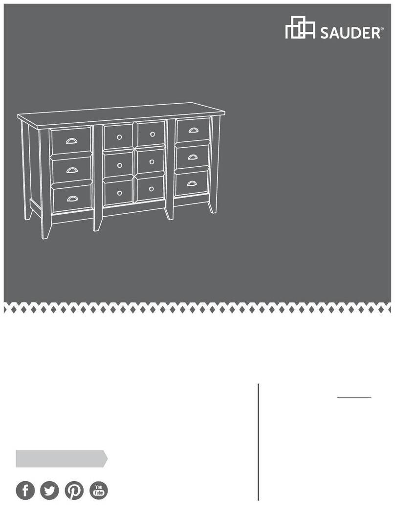
  9. Sauder Harbor View 401323 User manual

Sauder Harbor View 401323 User manual

NOTE: THIS INSTRUCTION
BOOKLET CONTAINS IMPORTANT
SAFETY INFORMATION.
PLEASE READ AND KEEP FOR
FUTURE REFERENCE.
Enlish p 1-24
Français p 25-28
Español p 29-32
Lot # 388805 02/18/16
Purchased: __________________
Be sure to ive us a rin before
makin any returns. 1-800-523-3987
5-Drawer Chest
Harbor View Collection | Model 401323
Need help? Visit Sauder.com to view video assembly tips or chat with a live rep.
Prefer the phone? Call 1-800-523-3987.
Share your journey!
sauder.com
Don't et cauht with
your pants on the
round.
Table of Contents Assembly Tools Required
2-3
4-5
6-24
25-28
29-32
33-34
35
Part Identification
Hardware Identification
Assembly Steps
Français
Español
Safety
Warranty
Hammer
Not actual size
No. 2 Phillips Screwdriver
Tip Shown Actual Size
Skip the power trip.
This time.
401323 www.sauder.com/servicesPae 2
Part Identification
åWhile not all parts are labeled, some of the parts will have a label or an inked letter on the ede
to help distinuish similar parts from each other. Use this part identification to help identify similar parts.
A3 RIGHT END (1)
B3 LEFT END (1)
C TOP (1)
D LOWER BRACE (2)
D24 SMALL DRAWER RIGHT SIDE (1)
D25 SMALL DRAWER LEFT SIDE (1)
D30 LARGE DRAWER RIGHT SIDE (4)
D31 LARGE DRAWER LEFT SIDE (4)
D170 SMALL DRAWER BACK (1)
D171 LARGE DRAWER BACK (4)
D945 DRAWER BOTTOM (5)
E UPPER BRACE (1)
F2 BACK (3)
G2
LARGE MIDDLE DRAWER FRONT (3)
H2
LARGE BOTTOM DRAWER FRONT (1)
L2 SMALL DRAWER FRONT (1)
M57 SKIRT (1)
M67 DRAWER BRACE (5)
Q UPPER BRACE MOLDING (1)
R BOTTOM MOLDING (1)
T FRONT MOLDING (1)
U RIGHT MOLDING (1)
V LEFT MOLDING (1)
BB FOOT (2)
Part Identification Now you know
our ABCs.
401323www.sauder.com/services Pae 3
A3
B3
C
D
E
F2
G2
H2
L2
Q
R
T
U
V
BB
BB
F2
F2
D
D170
D24
D945
D25
D171 D30
D945
D31
D171 D30
D945
D31 M67
M67
M67
M57
Hardware Identification
åScrews are shown actual size. You may receive extra hardware with your unit.
401323 www.sauder.com/servicesPae 4
HIDDEN CAM - 11
1F CAM DOWEL - 11
2F WASHER - 1
13M
SAFETY STRAP - 1
Locate this nylon SAFETY
STRAP (60M) to be used
later in assembly. Do not
accidentally throw away.
60M SAFETY DRYWALL
ANCHOR - 1
61M
XX WARNING LABEL - 1
(Refer to Step 18 for proper
location and application)
WARNING
Serious or fatal crushing injuries can occur
from furniture tip-over. To help prevent
tip-over:
• Place heaviest items in the lowest drawers.
• Unless specifically desined to accommodate, do not
set TVs or other heavy objects on top of this product.
• Never allow children to climb or han on drawers,
doors, or shelves.
• Never open more than one drawer at a time.
• If equipped with a drawer interlock system, do not
defeat or remove it.
Use of tip-over restraints may only reduce, but not
eliminate, the risk of tip-over.
This is a permanent label. Do not attempt to remove!
04/10 332296
MM SLIDE CAM - 10METAL PIN - 10
HH
MOLDING
CONNECTOR - 2
GG
DD TWIST-LOCK®FASTENER - 11
FOOT SCREW - 2
CC
KNOB - 10
EE
35AA UNIVERSAL CABINET RAIL - 10 35AC DRAWER RIGHT - 5 35AD DRAWER LEFT - 5
Hardware Identification
åScrews are shown actual size. You may receive extra hardware with your unit.
401323www.sauder.com/services Pae 5
BLACK 2-1/4" FLAT HEAD SCREW - 4
NN BLACK 1-7/8" FLAT HEAD SCREW - 2
OO
BLACK 1-5/8" PAN HEAD SCREW - 7
PP BLACK 1-1/4" FLAT HEAD SCREW - 10
QQ
BLACK 1-1/8" PAN HEAD SCREW - 4
RR TT GOLD 5/16" FLAT HEAD SCREW - 40
BLACK 9/16" LARGE HEAD SCREW - 1
VV 30S BLACK 1-9/16" FLAT HEAD SCREW - 25
Step 1 Look for this icon. It means a
video assembly tip is available at
www.sauder.com/services/tips
å Assemble your unit on a carpeted floor or on the empty
carton to avoid scratchin your unit or the floor.
å To bein assembly, push a SAUDER TWIST-LOCK®
FASTENER (DD) into the lare holes in the BRACES (D and E).
å Insert four METAL PINS (HH) into the small holes in the short
edes of the LOWER BRACES (D).
401323 www.sauder.com/servicesPae 6
DD
Do not tihten the TWIST-LOCK® FASTENERS in this step.
DD
DD
HH
D
D
E
Do not push TWIST-LOCK®
FASTENERS into these holes.
Do not push TWIST-LOCK®
FASTENERS into these holes.
(7 used)
Scan this QR code or go to this address:
http://qr.sauder.com/?ID=1422
to watch a video on how to assemble your unit.
å Push eleven HIDDEN CAMS (1F) into the BACKS (F2) and
DRAWER BRACES (M67). Then, insert the metal end of a
CAM DOWEL (2F) into each HIDDEN CAM.
Step 2
401323www.sauder.com/services Pae 7
(11 used)
Arrow
1F
2F
Do not tihten the HIDDEN CAMS in this step.
Insert the metal end of the CAM
DOWEL into the HIDDEN CAM.
Arrow
F2
F2
F2
M67
M67
M67
M67
M67
Step 3
401323 www.sauder.com/servicesPae 8
GOLD 5/16" FLAT HEAD SCREW
(20 used in this step)
TT
Remember:
Rihty tihty.
Lefty loosey.
1
B3
A3
1
2
3
1
2
3
1
2
3
1
2
3
1
2
31
2
31
2
31
2
3
Finished ede
å Fasten the UNIVERSAL CABINET RAILS* (35AA) to the
ENDS (A3 and B3). Use twenty GOLD 5/16" FLAT HEAD
SCREWS (TT) throuh holes #1 and #3.
å *patent pendin lide system
Glide end
Finished ede
Glide end
3
2
1
3
2
VIEW THE DRAWER GLIDE VIDEO
Step 4
401323www.sauder.com/services Pae 9
å Fasten the UPPER BRACE (E) to the UPPER BRACE
MOLDING (Q). Tihten three TWIST-LOCK® FASTENERS. How to use the SAUDER TWIST-LOCK®FASTENER
1. Insert the dowel end of the FASTENER into the hole of the
adjoinin part.
NOTE: The dowel end of the FASTENER must remain fully
inserted in the hole of the adjoinin part while lockin
the FASTENER.
2. Tihten the FASTENER with a Phillips screwdriver as tiht
as possible.
Dowel end
Q
E
Surface with
TWIST-LOCK®
FASTENERS
These surfaces
should be even.
Step 5
å Tap two MOLDING CONNECTORS (GG) into the notches
in the MOLDINGS (T, U, and V).
401323 www.sauder.com/servicesPae 10
Flat end Flat end
Use your hammer to tap the MOLDING CONNECTORS (GG) into the notches in the MOLDINGS.
GG
V
GG
U
T
Step 6
401323www.sauder.com/services Pae 11
å Fasten the LEFT END (B3) to the LEFT MOLDING (V). Use
two BLACK 2-1/4" FLAT HEAD SCREWS (NN).
BLACK 2-1/4" FLAT HEAD SCREW
(2 used in this step)
NN
B3
Finished ede
V
Step 7
å Insert six METAL PINS (HH) into the holes in the short
edes of the BACKS (F2).
å Fasten the BACKS (F2) to the LEFT END (B3). Tihten
three HIDDEN CAMS.
å NOTE: Be sure the METAL PINS in the BACKS insert into
the holes in the LEFT END.
Start Tihten
Arrow
Minimum
190 derees
Caution
Risk of damae or
injury. HIDDEN CAMS
must be completely
tihtened. HIDDEN
CAMS that are not
completely tihtened
may loosen, and parts
may separate. To
completely tihten:
Arrow
Maximum
210 derees
401323 www.sauder.com/servicesPae 12
HH
(6 used)
B3
F2
F2
F2
Surface with
HIDDEN CAMS
Surface with
HIDDEN CAMS
Surface with
HIDDEN CAMS
StepStep 8
å First, fasten the BOTTOM MOLDING (R) to the SKIRT (M57).
Use two BLACK 1-7/8" FLAT HEAD SCREWS (OO).
å Then, fasten one of the LOWER BRACES (D) to the
BOTTOM MOLDING (R). Use four BLACK 1-1/8" PAN
HEAD SCREWS (RR).
å NOTE: You should start each SCREW a few turns before
completely tihtenin any of them.
BLACK 1-1/8" PAN HEAD SCREW
(4 used in this step)
RR
BLACK 1-7/8" FLAT HEAD SCREW
(2 used in this step)
OO
R
M57
D
Rounded ede
Finished surface
401323www.sauder.com/services Pae 13
Surface and ede with
TWIST-LOCK® FASTENERS
Step
å Fasten the LOWER BRACES (D) to the LEFT END (B3).
Tihten two TWIST-LOCK® FASTENERS.
å NOTE: Be sure the METAL PINS in the edes of the LOWER
BRACES insert into the holes in the LEFT END.
å NOTE: Do not put any pressure on the LOWER BRACES (D)
until they are fastened to the RIGHT END in the next step.
Step 9
401323 www.sauder.com/servicesPae 14
Don't worry. It isn't
Rome. This can be built
in a day.
B3
R
D
D
Surface and ede with TWIST-LOCK® FASTENERS
StepStep 10
å Fasten the RIGHT END (A3) to the RIGHT MOLDING (U).
Use two BLACK 2-1/4" FLAT HEAD SCREWS (NN).
å Fasten the RIGHT END (A3) to the BACKS (F2). Tihten
three HIDDEN CAMS.
å NOTE: Be sure the METAL PINS in the edes of the backs
insert into the holes in the RIGHT END.
å Fasten the LOWER BRACES (D) to the RIGHT END (A3).
Tihten two TWIST-LOCK® FASTENERS.
å NOTE: Be sure the METAL PINS in the edes of the
LOWER BRACES insert into the holes in the RIGHT END. BLACK 2-1/4" FLAT HEAD SCREW
(2 used in this step)
NN
401323www.sauder.com/services Pae 15
U
A3
Finished ede
D
D
F2
F2
F2
Step
å Fasten the TOP (C) to the MOLDINGS (T, U, and V). Use
seven BLACK 1-5/8" PAN HEAD SCREWS (PP).
å NOTE: You should start each SCREW a few turns before
completely tihtenin any of them. Do not overtihten
the SCREWS.
Step 11
401323 www.sauder.com/servicesPae 16
V
C
T
U
Surface
with holes
Rounded ede
BLACK 1-5/8" PAN HEAD SCREW
(7 used in this step)
PP
StepStep 12
å Insert the dowel end of four TWIST-LOCK® FASTENERS (DD)
into the ENDS (A3 and B3). Follow the enlared diaram.
å NOTE: If you already pushed TWIST-LOCK® FASTENERS
into the UPPER BRACE (E), pull the FASTENERS back out of
the holes.
å Push the UPPER BRACE (E) onto the TWIST-LOCK®
FASTENERS in the ENDS (A3 and B3).
å Fasten the UPPER BRACE (E) to the ENDS (A3 and B3).
Tihten four TWIST-LOCK® FASTENERS.
E
B3
A3
E
B3
DD
Q
Push the UPPER BRACE (E) onto
the TWIST-LOCK® FASTENERS.
401323www.sauder.com/services Pae 17
DD
Step
401323 www.sauder.com/servicesPae 18
å Carefully turn two FOOT SCREWS (CC) a few turns into the
BOTTOM MOLDING (R).
å Next, turn a FOOT (BB) onto the other end of each FOOT
SCREW (CC). Turn the FEET clockwise until the FOOT
SCREWS are tiht in the BOTTOM MOLDING and FEET.
å NOTE: Do not overtihten the FOOT SCREWS.
Step 13
CC
BB
BB
R
Step 14
401323www.sauder.com/services Pae 19
å Insert the SMALL DRAWER SIDES (D24 and D25)
at an angle into the slot at each end of the SMALL
DRAWER FRONT (L2).
å Slide the DRAWER BOTTOM (D945) into the grooves in
the SMALL DRAWER SIDES (D24 and D25) and SMALL
DRAWER FRONT (L2).
å Fasten the DRAWER BRACE (M67) to the SMALL
DRAWER FRONT (L2). Tighten one HIDDEN CAM.
å Fasten the SMALL DRAWER BACK (D170) to the SMALL
DRAWER SIDES (D24 and D25) and DRAWER BRACE (M67).
Use five BLACK 1-9/16" FLAT HEAD SCREWS (30S).
Repeat this step for the LARGE DRAWERS.
The tabs should insert freely
into the slots. Gently tilt the
DRAWER SIDES side to side
until the tabs slip into the slots.
Surface with
HIDDEN CAM
12
34
Be sure the DRAWER
BOTTOM inserts into the
DRAWER FRONT roove.
With the palm of your hand, tap the
DRAWER BOTTOM down into the roove.
Groove
Arrow
Maximum
210 derees
Minimum
190 derees
L2
L2
L2
VIEW THE T-LOCK BOX VIDEO
D25
D24
D25
D945
D24
D24
D25
D170
Unfinished
surface
Be sure the
DRAWER
BOTTOM
inserts into
the DRAWER
BACK roove.
M67
M67
Start each screw a few turns before
completely tihtenin any of them.
BLACK 1-9/16" FLAT HEAD SCREW
(25 used in this step)
30S
Step 15
401323 www.sauder.com/servicesPae 20
å Insert a SLIDE CAM (MM) into the SMALL DRAWER SIDES (D24 and D25).
å Fasten a DRAWER RIGHT (35AC) to the SMALL DRAWER RIGHT SIDE (D24) and a DRAWER LEFT (35AD) to the SMALL
DRAWER LEFT SIDE (D25). Use four GOLD 5/16" FLAT HEAD SCREWS (TT) throuh holes #1 and #2.
å NOTE: The lides are not intended to rotate.
å NOTE: The screw head in the CAM must be visible throuh the slotted hole in the SLIDE.
å Fasten two KNOBS (EE) to the SMALL DRAWER FRONT (L2). Use two BLACK 1-1/4" FLAT HEAD SCREWS (QQ).
å Repeat this step for the LARGE DRAWERS.
1
2
1
2
GOLD 5/16" FLAT HEAD SCREW
(20 used in this step)
TT
Screw head - turn CAM to line up holes in
the SLIDES with holes in DRAWER SIDES
MM
MM
BLACK 1-1/4" FLAT HEAD SCREW
(10 used for the KNOBS)
QQ
D24
D25
L2
EE
Glide end
VIEW THE DRAWER GLIDE VIDEO
Glide end

Other Sauder Indoor Furnishing manuals
Sauder Credenza 420723 User manual

Sauder

Sauder Credenza 420723 User manual

Sauder Shoal Creek 411222 User manual

Sauder

Sauder Shoal Creek 411222 User manual

Sauder Pinwheel Collection 422600 User manual

Sauder

Sauder Pinwheel Collection 422600 User manual

Sauder Shoal Creek 409714 User manual

Sauder

Sauder Shoal Creek 409714 User manual

Sauder Dakota Pass 422596 User manual

Sauder

Sauder Dakota Pass 422596 User manual

Sauder Hammond 428247 User manual

Sauder

Sauder Hammond 428247 User manual

Sauder Dakota Pass 424120 User manual

Sauder

Sauder Dakota Pass 424120 User manual

Sauder Dixon Dowel Stool Short User manual

Sauder

Sauder Dixon Dowel Stool Short User manual

Sauder Manhattan Gate 429257 User manual

Sauder

Sauder Manhattan Gate 429257 User manual

Sauder 408995 User manual

Sauder

Sauder 408995 User manual

Sauder Harbor View 417586 User manual

Sauder

Sauder Harbor View 417586 User manual

Sauder Shoal Creek Night Stand 410412 User manual

Sauder

Sauder Shoal Creek Night Stand 410412 User manual

Sauder Boulevard Cafe 429410 User manual

Sauder

Sauder Boulevard Cafe 429410 User manual

Sauder 412314 User manual

Sauder

Sauder 412314 User manual

Sauder 426930 User manual

Sauder

Sauder 426930 User manual

Sauder Costa L-Desk 419956 User manual

Sauder

Sauder Costa L-Desk 419956 User manual

Sauder Dakota Pass 422593 User manual

Sauder

Sauder Dakota Pass 422593 User manual

Sauder Via 419708 User manual

Sauder

Sauder Via 419708 User manual

Sauder Shoal Creek 420166 User manual

Sauder

Sauder Shoal Creek 420166 User manual

Sauder Boulevard Cafe 420667 User manual

Sauder

Sauder Boulevard Cafe 420667 User manual

Sauder 431238 User manual

Sauder

Sauder 431238 User manual

Sauder 423032 User manual

Sauder

Sauder 423032 User manual

Sauder WHISKER User manual

Sauder

Sauder WHISKER User manual

Sauder 420477 User manual

Sauder

Sauder 420477 User manual

Popular Indoor Furnishing manuals by other brands

Wickes Dakota White Matt Slab Assembly manual

Wickes

Wickes Dakota White Matt Slab Assembly manual

Madeleine Home MH-BD-11506 Assembly instructions

Madeleine Home

Madeleine Home MH-BD-11506 Assembly instructions

Ameriwood HOME 5950103COM Assembly manual

Ameriwood HOME

Ameriwood HOME 5950103COM Assembly manual

Cattelan Italia Piquant Assembling instructions

Cattelan Italia

Cattelan Italia Piquant Assembling instructions

Sundrape 5060 Assembly instructions

Sundrape

Sundrape 5060 Assembly instructions

Palace Imports 7201 Assembly instructions

Palace Imports

Palace Imports 7201 Assembly instructions

Core Products Corona CX-DINCORLGE Assembly instructions

Core Products

Core Products Corona CX-DINCORLGE Assembly instructions

DeWalt DXST4500BLK-W instruction manual

DeWalt

DeWalt DXST4500BLK-W instruction manual

Steelcase Slatwall Skin quick start guide

Steelcase

Steelcase Slatwall Skin quick start guide

Home Decorators Collection LAREDA 2206VA48-201900 Assembly instructions

Home Decorators Collection

Home Decorators Collection LAREDA 2206VA48-201900 Assembly instructions

Pine Crafter Furniture 072 instructions

Pine Crafter Furniture

Pine Crafter Furniture 072 instructions

Simpli Home AXCPF-23-TL quick start guide

Simpli Home

Simpli Home AXCPF-23-TL quick start guide

Argos Atlantic 759/0692 Assembly instructions

Argos

Argos Atlantic 759/0692 Assembly instructions

KEUCO Plan 32930 0001 Series Mounting instruction

KEUCO

KEUCO Plan 32930 0001 Series Mounting instruction

IKEA METOD Assembly instructions

IKEA

IKEA METOD Assembly instructions

Belnick CX-1179H-BK-GG Assembly instructions

Belnick

Belnick CX-1179H-BK-GG Assembly instructions

Ameriwood HOME 5393500COM Assembly instructions

Ameriwood HOME

Ameriwood HOME 5393500COM Assembly instructions

Desa C21TP Assembly and installation instructions

Desa

Desa C21TP Assembly and installation instructions

manuals.online logo
manuals.online logoBrands
  • About & Mission
  • Contact us
  • Privacy Policy
  • Terms and Conditions

Copyright 2025 Manuals.Online. All Rights Reserved.