manuals.online logo
Brands
  1. Home
  2. •
  3. Brands
  4. •
  5. Sauder
  6. •
  7. Indoor Furnishing
  8. •
  9. Sauder Summit Station 425015 User manual

Sauder Summit Station 425015 User manual

sauder.com
NOTE: THIS INSTRUCTION
BOOKLET CONTAINS IMPORTANT
SAFETY INFORMATION.
PLEASE READ AND KEEP FOR
FUTURE REFERENCE.
sauder.com
CONTACT US FIRST
BEFORE MAKING ANY RETURNS TO THE STORE.
Share your journey!
sauder.com
CONTACT US FIRST
BEFORE MAKING ANY RETURNS TO THE RETAILER.
Visit sauder.com/service to order replacement parts, view video assembly tips, or chat with a live rep.
Prefer the phone? Give us a ring at 1-800-523-3987.
Customer Service is available Monday-Friday - 9 a.m. to 5:30 p.m. EST (except holidays)
Sauder.com
Lot # 533064 09/26/19
Purchased: __________________
English pg 1-28
Français pg 29-32
Español pg 33-36
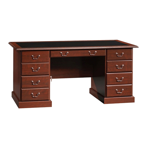
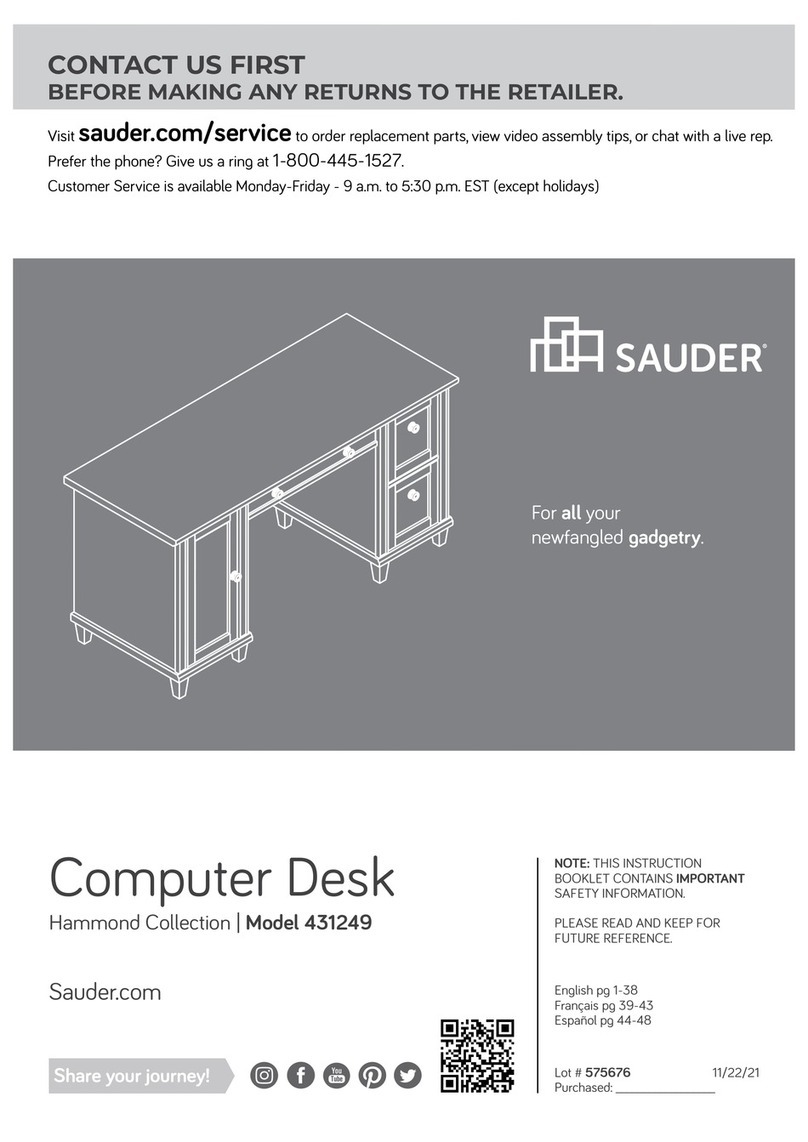
Desk
Summit Station Collection | Model 425015
The original desktop.
Table of Contents Assembly Tools Required
Part Identification
Hardware Identification
Assembly Steps
Français
Español
Safety
Warranty
Hammer
Not actual size
No. 2 Phillips Screwdriver
Tip Shown Actual Size
Skip the power trip.
This time.
3
4-5
6-28
29-32
33-36
37-38
39
425015 www.sauder.com/servicePage 2
Part Identification
åWhile not all parts are labeled, some of the parts will have a label or an inked letter on the edge
to help distinguish similar parts from each other. Use this part identification to help identify similar parts.
Now you know
our ABCs.
A RIGHT END (1)
B LEFT END (1)
B51 PENCIL DRAWER BOTTOM (1)
C MODESTY PANEL (1)
D UPRIGHT (1)
D14 FILE RIGHT DRAWER SIDE (1)
D15 FILE LEFT DRAWER SIDE (1)
D78 FILE DRAWER BACK (1)
D266 PENCIL RIGHT DRAWER SIDE (1)
D267 PENCIL LEFT DRAWER SIDE (1)
D540 PENCIL DRAWER BACK (1)
D541 PENCIL DRAWER BOX FRONT (1)
D716 FILE DRAWER BOTTOM (1)
E BOTTOM (1)
F FILE DRAWER FRONT (1)
G LEFT BRACE (1)
H LEFT BOTTOM MOLDING (1)
J FRONT/BACK MOLDING (2)
K LONG BRACE (1)
LPEDESTAL LEFT FRONT/RIGHT
REAR LEG (2)
M BACK (1)
N BRACE (1)
O PENCIL DRAWER FRONT (1)
PPEDESTAL RIGHT FRONT/LEFT
REAR LEG (2)
Q DESK LEFT FRONT LEG (1)
R DESK LEFT REAR LEG (1)
S RIGHT BOTTOM MOLDING (1)
T TOP (1)
425015www.sauder.com/service Page 3
D15
D540
A
B
C
D
E
F
G
HJ
KL
M
N
O
P
Q
R
S
T
D541
D716
D14
D78
D267
D266
B51
J
P
L
Hardware Identification
åScrews are shown actual size. You may receive extra hardware with your unit.
FILE GLIDE - 2
4B
35GA CABINET RIGHT - 1 35GB CABINET LEFT - 1 35GC DRAWER RIGHT - 1 35GD DRAWER LEFT - 1
(EXTENSION SET SHOWN SEPARATED)
EXTENSION RAIL - 2
35MA EXTENSION SLIDE - 2
35MC 10A SLIDE CAM - 2
425015 www.sauder.com/servicePage 4
HIDDEN CAM - 38
1F CAM DOWEL - 20
2F CAM SCREW - 18
8F WOOD DOWEL - 11
15F
CROSS SLOTTED DOWEL - 2
24F EXTENSION BRACKET - 2
43G PULL - 1
35K
GLUE - 1
54M GROMMET CAP - 1
1P GROMMET - 1
10P CAM COVER - 6
75P
Hardware Identification
åScrews are shown actual size. You may receive extra hardware with your unit.
425015www.sauder.com/service Page 5
BLACK 9/16" LARGE HEAD SCREW - 4
1S 3S GOLD 5/16" FLAT HEAD SCREW - 16
BLACK 7/8" LARGE HEAD SCREW - 4
17S 30S BLACK 1-9/16" FLAT HEAD SCREW - 8
BLACK 7/8" MACHINE SCREW - 2
37S BLACK 2-3/8" FLAT HEAD BOLT - 2
103S
BLACK 1-15/16" FLAT HEAD SCREW - 2
113S
Step 1
425015 www.sauder.com/servicePage 6
Look for this icon. It means a
video assembly tip is available at
www.sauder.com/service/tips
å Assemble your unit on a carpeted floor or on the empty carton to
avoid scratching your unit or the floor.
å Push twenty HIDDEN CAMS (1F) into the ENDS (A and B),
MODESTY PANEL (C), UPRIGHT (D), BOTTOM (E), BACK (M), and
BRACE (N). Then, insert the metal end of a CAM DOWEL (2F) into
each HIDDEN CAM.
A
B
C
D
E
M
N
Insert the metal end of the CAM
DOWEL into the HIDDEN CAM.
Arrow
Do not tighten the HIDDEN CAMS in this step.
Arrow
1F
2F
Metal end
Insert the metal end of the CAM
DOWEL into the HIDDEN CAM.
The arrow in the HIDDEN
CAM must point toward the
hole in the edge of the board.
Hole
Arrow
1F
2F
(20 used)
Metal end
å Push eighteen HIDDEN CAMS (1F) into the remaining
holes of the ENDS (A and B), UPRIGHT (D), LEFT
BRACE (G), and BOTTOM MOLDINGS (H and S).
Step 2
425015www.sauder.com/service Page 7
A
B
D
G
H
S
Arrow
The arrow in the HIDDEN
CAM must point toward the
hole in the edge of the board.
Hole
1F
(18 used)
Arrow
1F
Arrow
åTurn eighteen CAM SCREWS (8F) into the LEGS (L, P, Q, and R).
åFirst, fill the hole in the end of the LEG (Q) 1/4 to 1/2 full with
GLUE (54M). Then, insert the WOOD DOWEL (15F) into the hole.
Wipe away the excess GLUE.
Step 3
425015 www.sauder.com/servicePage 8
L
P
Q
R
P
L
8F
(18 used)
Fill the holes 1/4 to 1/2 full with GLUE.
Inspect the parts thoroughly before
assembling. Disassembly of glued
parts is extremely dicult.
Caution
!
54M
15F
åFirst, fill the holes in the LEGS (Q and R) 1/4 to 1/2 full with
GLUE (54M). Then, insert the WOOD DOWELS (15F) into
the holes. Wipe away the excess GLUE.
åNow, fill the holes in the LEFT END (B) and LEFT BRACE (G)
1/4 to 1/2 full with GLUE.
åFasten the LEGS (Q and R) to the LEFT END (B) and LEFT
BRACE (G). Tighten six HIDDEN CAMS. Wipe away the
excess GLUE.
åNOTE: Be sure the WOOD DOWELS in the LEGS insert into
the LEFT END and LEFT BRACE.
Step 4
425015www.sauder.com/service Page 9
B
G
Q
R
Fill the holes 1/4 to 1/2 full with GLUE.
Inspect the parts thoroughly before
assembling. Disassembly of glued
parts is extremely dicult.
Caution
!
54M
15F
1
2
Surface
with
HIDDEN
CAMS
These surfaces
should be even.
Edge with
CAM DOWELS
15F
Surface
with
HIDDEN
CAMS
å Fasten the LEGS (L and P) to the RIGHT END (A)
and RIGHT BOTTOM MOLDING (S). Tighten six
HIDDEN CAMS.
å NOTE: Position the RIGHT BOTTOM MOLDING (S)
exactly as shown.
Step 5
425015 www.sauder.com/servicePage 10
A
P
S
L
Surface
with
HIDDEN
CAMS
These surfaces
should be even.
Edge with
CAM DOWELS
Surface
with
HIDDEN
CAMS
The holes are
closer to this edge.
å Fasten the LEGS (L and P) to the UPRIGHT (D) and LEFT
BOTTOM MOLDING (H). Tighten six HIDDEN CAMS.
å NOTE: Position the LEFT BOTTOM MOLDING (H) exactly
as shown.
Step 6
425015www.sauder.com/service Page 11
D
H
L
P
Surface
with
HIDDEN
CAMS
These surfaces
should be even.
Edge with
CAM DOWELS
Surface
with
HIDDEN
CAMS
This hole
must be here.
Step 7
425015 www.sauder.com/servicePage 12
A
D
Open end
å Separate the EXTENSION SLIDES (35MC) from the EXTENSION RAILS (35MA) as
shown in the upper diagram below. Be prepared, the parts are greasy.
å Fasten the EXTENSION RAILS (35MA) to the RIGHT END (A) and UPRIGHT (D). Use
four GOLD 5/16" FLAT HEAD SCREWS (3S) through holes #1 and #3..
å NOTE: For each EXTENSION RAIL, turn a SCREW into the hole shown in the enlarged
diagram. Then, slide the inner cartridge of the EXTENSION RAIL in to find the other hole
that lines up with the hole in the END/UPRIGHT. Turn a SCREW into this hole.
å NOTE: The EXTENSION SLIDES (35MC) will be used later for the FILE DRAWER.
Open end
Push the black lever in and pull the SLIDE from the RAIL.
35MA
35MC
3
2
1
1
2
3
GOLD 5/16" FLAT HEAD SCREW
(4 used for the RAILS)
3S
These holes
must be here.
These holes
must be here.
å Carefully flip the UPRIGHT (D) over.
å Fasten two EXTENSION BRACKETS (43G) to the UPRIGHT (D). Use four
BLACK 9/16" LARGE HEAD SCREWS (1S).
å Fasten the CABINET RIGHT (35GA) to the EXTENSION BRACKETS (43G)
on the UPRIGHT (D). Use two GOLD 5/16" FLAT HEAD SCREWS (3S)
through holes #1 and #3.
å NOTE: Use the exact holes shown in the EXTENSION BRACKETS.
å Fasten the CABINET LEFT (35GB) to the LEFT END (B). Use two GOLD
5/16" FLAT HEAD SCREWS (3S) through holes #1 and #3.
Step 8
425015www.sauder.com/service Page 13
B
D
1
2
3
1
2
3
Roller end
Roller end
GOLD 5/16" FLAT HEAD SCREW
(4 used for the RAILS)
3S
BLACK 9/16" LARGE HEAD SCREW
(4 used for the BRACKETS)
1S
43G
å Fasten the MODESTY PANEL (C) to the LEFT
END (B). Tighten two HIDDEN CAMS.
Step 9
425015 www.sauder.com/servicePage 14
Start Tighten
Arrow
Minimum
190 degrees
Caution
Risk of damage or
injury. HIDDEN CAMS
must be completely
tightened. HIDDEN
CAMS that are not
completely tightened
may loosen, and parts
may separate. To
completely tighten:
Arrow
Maximum
210 degrees
C
Surface
with
HIDDEN
CAMS
B
Roller end
åFirst, fill the hole in the TOP (T) 1/4 to 1/2 full with GLUE (54M).
åThen, fasten the LEFT END (B) and MODESTY PANEL (C) to the
TOP (T). Tighten four HIDDEN CAMS.
åNOTE: Be sure the WOOD DOWEL in the LEG (Q) inserts into
the TOP. Wipe away the excess GLUE.
Step 10
425015www.sauder.com/service Page 15
Arrow
Minimum
190 degrees
Maximum
210 degrees
C
B
T
Fill the holes 1/4 to 1/2 full with GLUE.
Inspect the parts thoroughly before
assembling. Disassembly of glued
parts is extremely dicult.
Caution
!
54M
Q
Meet Part (T). This component has
been engineered to be lighter, stronger,
faster… well ok. Not technically faster.
But definitely makes for a sturdier
Desk that’s easier to assemble and
friendlier to the environment.
The large hole
must be here.
åPush two CROSS-SLOTTED DOWELS (24F) into the LONG BRACE (K)
as shown.
åNOTE: The threads in the DOWEL should be pointed toward the hole in
the edge of the LONG BRACE.
åFirst, fill the holes in the ends of the LONG BRACE (K) 1/4 to 1/2 full
with GLUE (54M). Then, insert the WOOD DOWELS (15F) into the holes.
Wipe away the excess GLUE.
åNow, fill the hole in the LEFT BRACE (G) 1/4 to 1/2 full with GLUE.
åFasten the LONG BRACE (K) to the LEFT BRACE (G). Use one BLACK
2-3/8" FLAT HEAD BOLT (103S).
åNOTE: The BOLT will thread into the DOWEL in the LONG BRACE.
åNOTE: Be sure the WOOD DOWEL in the LONG BRACE inserts into the
LEFT BRACE. Wipe away the excess GLUE.
Step 11
425015 www.sauder.com/servicePage 16
24F
The long slot should face up
and be parallel to the long
edges of the SIDE SKIRTS.
KK
Fill the holes 1/4 to 1/2 full with GLUE.
Inspect the parts thoroughly before
assembling. Disassembly of glued
parts is extremely dicult.
Caution
!
54M
15F
G
103S
BLACK 2-3/8" FLAT HEAD BOLT
(1 used for the LONG BRACE)
Surface with slotted dowels
åFirst, fill the hole in the LEFT BOTTOM MOLDING (H) 1/4 to 1/2
full with GLUE.
åNext, fasten the UPRIGHT (D) to the TOP (T). Tighten two
HIDDEN CAMS.
åNOTE: Be sure the WOOD DOWEL in the LONG BRACE (K)
inserts into the LEFT BOTTOM MOLDING (H). Wipe away the
excess GLUE.
åFasten the LEFT BOTTOM MOLDING (H) to the LONG BRACE (K).
Use one BLACK 2-3/8" FLAT HEAD BOLT (103S).
åFasten the UPRIGHT (D) to the MODESTY PANEL (C). Use two
BLACK 1-15/16" FLAT HEAD SCREWS (113S).
Step 12
425015www.sauder.com/service Page 17
Arrow
Minimum
190 degrees
Maximum
210 degrees
103S
BLACK 2-3/8" FLAT HEAD BOLT
(1 used for the LONG BRACE)
Fill the holes 1/4 to 1/2 full with GLUE.
Inspect the parts thoroughly before
assembling. Disassembly of glued
parts is extremely dicult.
Caution
!
K
T
D
H
C
BLACK 1-15/16" FLAT HEAD SCREW
(2 used for the MODESTY PANEL)
113S
103S
54M
åFirst, fill the holes in the BRACE (N) 1/4 to 1/2 full with
GLUE (54M). Then, insert the WOOD DOWELS (15F)
into the holes. Wipe away the excess GLUE.
åNow, fill the hole in the UPRIGHT (D) 1/4 to 1/2 full
with GLUE.
åFasten the BRACE (N) to the UPRIGHT (D). Tighten
one HIDDEN CAM.
åNOTE: Be sure the WOOD DOWEL in the BRACE
inserts into the UPRIGHT. Wipe away the excess GLUE.
åInsert the CAM DOWELS in the edge of the BACK (M)
into the UPRIGHT (D) but do not tighten them.
Step 13
425015 www.sauder.com/servicePage 18
Arrow
Minimum
190 degrees
Maximum
210 degrees
MN
Fill the holes 1/4 to 1/2 full with GLUE.
Inspect the parts thoroughly before
assembling. Disassembly of glued
parts is extremely dicult.
Caution
!
15F
54M
Surface with
HIDDEN CAMS
Surface
with
HIDDEN
CAMS
Finished edge
D
15F
NOTE: Do not
tighten in this step.
Finished
edge
å Slide the FRONT/BACK MOLDINGS* (J) onto the
notched edges of the BOTTOM (E).
å Fasten the BOTTOM (E) to the LEFT BOTTOM
MOLDING (H). Tighten two HIDDEN CAMS.
å *U.S. Patent No. 5,499,886
Step 14
425015www.sauder.com/service Page 19
Arrow
Minimum
190 degrees
Maximum
210 degrees
Notched edge
Notched edge
These surfaces
should be even.
E
J
J
Surface with
HIDDEN CAMS
H
E
The groove
is closer to
this edge.
The groove
is closer to
this edge.
Surface with
HIDDEN CAMS
åFirst, fill the hole in the RIGHT END (A) 1/4 to 1/2 full
with GLUE.
åNext, fasten the RIGHT END (A) to the BOTTOM (E),
BACK (M), BRACE (N), and TOP (T). Tighten seven
HIDDEN CAMS.
åNOTE: You may need to lift the BACK (M) up
slightlyto align the holes.
åNOTE: Be sure the WOOD DOWEL in the BRACE (N)
inserts into the RIGHT END (A). Wipe away the
excess GLUE.
åFasten the BACK (M) to the UPRIGHT (D). Tighten
two HIDDEN CAMS.
Step 15
425015 www.sauder.com/servicePage 20
Arrow
Minimum
190 degrees
Maximum
210 degrees
54M
Fill the holes 1/4 to 1/2 full with GLUE.
Inspect the parts thoroughly before
assembling. Disassembly of glued
parts is extremely dicult.
Caution
!
T
A
MN
E
D
SNOTE: Tighten two HIDDEN
CAMS to fasten the BACK (M)
to the UPRIGHT (D).

Other Sauder Indoor Furnishing manuals
Sauder WoodTrac closets 359540 User manual

Sauder

Sauder WoodTrac closets 359540 User manual

Sauder Steel River Credenza 427849 User manual

Sauder

Sauder Steel River Credenza 427849 User manual

Sauder Shoal Creek 411201 User manual

Sauder

Sauder Shoal Creek 411201 User manual

Sauder 412091 User manual

Sauder

Sauder 412091 User manual

Sauder Boulevard Cafe 420701 User manual

Sauder

Sauder Boulevard Cafe 420701 User manual

Sauder 416519 User manual

Sauder

Sauder 416519 User manual

Sauder Boone Mountain 416562 User manual

Sauder

Sauder Boone Mountain 416562 User manual

Sauder Anywhere Dakota Pass 418231 User manual

Sauder

Sauder Anywhere Dakota Pass 418231 User manual

Sauder Barrister Lane Hutch 418295 User manual

Sauder

Sauder Barrister Lane Hutch 418295 User manual

Sauder Parklane 423107 User manual

Sauder

Sauder Parklane 423107 User manual

Sauder Storage Cabinet 419496 User manual

Sauder

Sauder Storage Cabinet 419496 User manual

Sauder Worksense BERGEN CIRCLE 426289 User manual

Sauder

Sauder Worksense BERGEN CIRCLE 426289 User manual

Sauder Lateral File User manual

Sauder

Sauder Lateral File User manual

Sauder Dakota Pass Armoire 419077 User manual

Sauder

Sauder Dakota Pass Armoire 419077 User manual

Sauder Original Cottage Collection 414684 User manual

Sauder

Sauder Original Cottage Collection 414684 User manual

Sauder STEADFAST 402932 User manual

Sauder

Sauder STEADFAST 402932 User manual

Sauder 408761 User manual

Sauder

Sauder 408761 User manual

Sauder Shoal Creek 422194 User manual

Sauder

Sauder Shoal Creek 422194 User manual

Sauder Boulevard Cafe 422355 User manual

Sauder

Sauder Boulevard Cafe 422355 User manual

Sauder Trestle 424127 User manual

Sauder

Sauder Trestle 424127 User manual

Sauder Harbor View 420471 User manual

Sauder

Sauder Harbor View 420471 User manual

Sauder Barrister Lane 418270 User manual

Sauder

Sauder Barrister Lane 418270 User manual

Sauder Edge Water Series User manual

Sauder

Sauder Edge Water Series User manual

Sauder 408726 User manual

Sauder

Sauder 408726 User manual

Popular Indoor Furnishing manuals by other brands

Cooper Lighting Lumark VL Specification sheet

Cooper Lighting

Cooper Lighting Lumark VL Specification sheet

Mocka Reese Assembly instructions

Mocka

Mocka Reese Assembly instructions

Lightolier Calculite C4CFL18 specification

Lightolier

Lightolier Calculite C4CFL18 specification

Furinno 12078 Assembly instruction

Furinno

Furinno 12078 Assembly instruction

Mocka Trestle Desk Assembly instructions

Mocka

Mocka Trestle Desk Assembly instructions

Argos 473/8639 Assembly instructions

Argos

Argos 473/8639 Assembly instructions

True 9212 operating instructions

True

True 9212 operating instructions

Greentouch Scott Living 1053VA-54-221 Assembly / care & use instructions

Greentouch

Greentouch Scott Living 1053VA-54-221 Assembly / care & use instructions

JR Home IF-DK225 Assembly instructions

JR Home

JR Home IF-DK225 Assembly instructions

Lifely Pebble Series Assembly instructions

Lifely

Lifely Pebble Series Assembly instructions

Living Spaces revive owner's manual

Living Spaces

Living Spaces revive owner's manual

Maintal Figaro EB SH52 OHNE Assembly instructions

Maintal

Maintal Figaro EB SH52 OHNE Assembly instructions

Southern Enterprises CM5071 Assembly instructions

Southern Enterprises

Southern Enterprises CM5071 Assembly instructions

Costway JV10615US-DK user manual

Costway

Costway JV10615US-DK user manual

Walker Edison BWTLD46 Assembly instructions

Walker Edison

Walker Edison BWTLD46 Assembly instructions

Zoovilla TOY0133710000 quick start guide

Zoovilla

Zoovilla TOY0133710000 quick start guide

Elle Decor Stara 6773809 Assembly instructions and warranty information

Elle Decor

Elle Decor Stara 6773809 Assembly instructions and warranty information

la vie vert P1 Assembly instruction

la vie vert

la vie vert P1 Assembly instruction

manuals.online logo
manuals.online logoBrands
  • About & Mission
  • Contact us
  • Privacy Policy
  • Terms and Conditions

Copyright 2025 Manuals.Online. All Rights Reserved.