manuals.online logo
Brands
  1. Home
  2. •
  3. Brands
  4. •
  5. Sauder
  6. •
  7. Indoor Furnishing
  8. •
  9. Sauder Hammond 431249 User manual

Sauder Hammond 431249 User manual

sauder.com
NOTE: THIS INSTRUCTION
BOOKLET CONTAINS IMPORTANT
SAFETY INFORMATION.
PLEASE READ AND KEEP FOR
FUTURE REFERENCE.
sauder.com
CONTACT US FIRST
BEFORE MAKING ANY RETURNS TO THE STORE.
sauder.com
CONTACT US FIRST
BEFORE MAKING ANY RETURNS TO THE RETAILER.
Visit sauder.com/service to order replacement parts, view video assembly tips, or chat with a live rep.
Prefer the phone? Give us a ring at 1-800-445-1527.
Customer Service is available Monday-Friday - 9 a.m. to 5:30 p.m. EST (except holidays)
Sauder.com
Share your journey!
English pg 1-38
Français pg 39-43
Español pg 44-48
Lot # 575676 11/22/21
Purchased: __________________
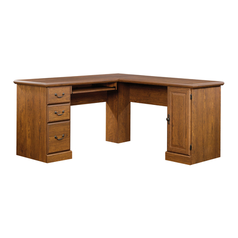
Computer Desk
Hammond Collection | Model 431249
For all your
newfangled gadgetry.
Part Identification
Hardware Identification
Hardware Usage Guide
Assembly Steps
Français
Español
Safety
Warranty
No. 2 Phillips Screwdriver
Tip Shown Actual Size
Table of Contents Assembly Tools Required
2-3
4-5
6
7-38
39-43
44-48
49-50
51
A TOP (1)
B BOTTOM (2)
C LEFT END (1)
D RIGHT END (1)
E LEFT UPRIGHT (1)
F RIGHT UPRIGHT (1)
G SHORT BRACE (1)
H BACK (2)
J ADJUSTABLE SHELF (1)
K DOOR (1)
L MODESTY PANEL (1)
M LEFT DRAWER SIDE (2)
N RIGHT DRAWER SIDE (2)
O DRAWER FRONT (2)
P DRAWER BOTTOM (2)
Q DRAWER BACK (2)
R LEFT KEYBOARD SIDE (1)
S RIGHT KEYBOARD SIDE (1)
T KEYBOARD SHELF (1)
U KEYBOARD FRONT (1)
V KEYBOARD BACK (1)
Z FOOT (8)
åWhile not all parts are labeled, some of the parts will have a label or an inked letter on the edge
to help distinguish similar parts from each other. Use this part identification to help identify similar parts.
Now you know
our ABCs.
Part Identification
Page 2 www.sauder.com/service 431249
Part Identification
A
B
C
D
E
F
G
H
J
K
L
M
N
O
P
Q
R
S
T
U
V
B
H
M
N
O
P
Q
Z
Z
Page 3www.sauder.com/service431249
Hardware Identification
åScrews are shown actual size. You may receive extra hardware with your unit.
APPLIQUE CARD - 5
10
LARGE WOOD
DOWEL - 54
8
KNOB SET - 5
11
SMALL WOOD
DOWEL - 16
9
HIDDEN
CAM - 34
5CAM SCREW - 42
7
SMALL HIDDEN
CAM - 8
6
FILE BAR
CLIP - 8
24
L-WRENCH - 1
19
HINGE - 2
13
RUBBER BUMPER- 2
23
MAGNETIC CATCH - 3
20
3EXTENSION RAIL - 2 4EXTENSION SLIDE - 2
2LONG EXTENSION
SLIDE - 4
1LONG EXTENSION
RAIL - 4
(EXTENSION SET SHOWN SEPARATED)(EXTENSION SET SHOWN SEPARATED)
FILE BAR - 4
25
STRIKE PLATE - 2
21
14 LARGE
GROMMET - 3
15 GROMMET - 2 GROMMET CAP- 1
16 SMALL GROMMET - 1
17
DOOR
HINGE - 2
12
CORD CLIP - 1
18
DOOR STRIKE
PLATE - 1
22
Page 4 www.sauder.com/service 431249
Hardware Identification
åScrews are shown actual size. You may receive extra hardware with your unit.
SHELF PIN - 4
26
1-3/8" FLAT HEAD SCREW - 20
28
1" MACHINE SCREW - 1
30 5/8" FLAT HEAD SCREW - 36
31
2-3/4" HEX HEAD SCREW - 16
27
1/2" FLAT HEAD SCREW - 24
33
NARROW 1/2" FLAT HEAD SCREW - 3
34
NARROW 5/8" FLAT HEAD SCREW - 6
32
1/2" MACHINE SCREW - 2
35
1-3/8" MACHINE SCREW - 2
29
HIDDEN WIRELESS Qi COMPATIBLE
CHARGER by EGGTRONIC - Item 425905
(sold separately)
p
o
w
e
r
e
d
b
y
E
G
G
T
R
O
N
I
C
p
o
w
e
r
e
d
b
y
E
G
G
T
R
O
N
I
C
p
o
w
e
r
e
d
b
y
E
G
G
T
R
O
N
I
C
p
o
w
e
r
e
d
b
y
E
G
G
T
R
O
N
I
C
Page 5www.sauder.com/service431249
Hardware Usage Guide
HOW TO USE A HIDDEN CAM & CAM SCREW OR CAM DOWEL
NOTE: Various CAM SCREWS or a CAM DOWEL may be used.
Cam Screws Cam Dowel
Turn the CAM SCREW or
gently tap the CAM DOWEL
until the shoulder is against
the surface of the part.
1.
Hidden Cam
Arrow
Push a HIDDEN CAM into
the part. The arrow in the
HIDDEN CAM must point
toward the hole in the
edge of the board.
Hole
2.
3.
1
2
Insert the CAM SCREW or CAM DOWEL into the
HIDDEN CAM. Tighten the HIDDEN CAM.
Page 6 www.sauder.com/service 431249
Step 1
å Assemble your unit on a carpeted floor or on the empty
carton to avoid scratching your unit or the floor.
å Turn five CAM SCREWS (7) into the exact holes shown in
both surfaces of the LEFT UPRIGHT (E).
å Then, push four HIDDEN CAMS (5) into the LEFT
UPRIGHT (E).
Look for this icon. It means a video assembly tip is
available at www.sauder.com/service/tips
Find the numbered video or scan the QR code.
E
E
F
L
I
P
O
V
E
R
E
1
Some assembly
(and snacks) required.
5
Arrow
Arrow
5
7
7
Page 7www.sauder.com/service431249
StepStep 2
E
å Separate the EXTENSION SLIDES (4) from the EXTENSION RAILS (3) as shown in the upper diagram below. Be
prepared, the parts are greasy.
å Fasten an EXTENSION RAIL (3) to the LEFT UPRIGHT (E). Use three 5/8" FLAT HEAD SCREWS (31).
å NOTE: For the EXTENSION RAIL, turn a SCREW into the hole shown in the diagram. Then, slide the inner cartridge of
the EXTENSION RAIL in to find the other holes that lines up with the holes in the LEFT UPRIGHT. Turn a SCREW into
these holes.
å NOTE: The EXTENSION SLIDES will be used later for the KEYBOARD SHELF.
Use these holes.
BLACK 5/8" FLAT HEAD SCREW
(3 used in this step)
31
7
Push the black lever and pull
the SLIDE from the RAIL.
3
4
3
Closed end
Closed end
Molding
Surface without
HIDDEN CAMS
Page 8 www.sauder.com/service 431249
å Turn two CAM SCREWS (7) into the exact holes shown in
the LEFT END (C).
å Then, push eight HIDDEN CAMS (5) into the LEFT
END (C) and one of the BACKS (H).
Step 3
H
C
1
5
Arrow
Arrow
5
7
Arrow 5
5
Arrow
Page 9www.sauder.com/service431249
å Insert four LARGE WOOD DOWELS (8) into the long
edges of the BACK (H).
å Fasten the BACK (H) to the LEFT END (C) and LEFT
UPRIGHT (E). Tighten four HIDDEN CAMS.
å NOTE: Be sure the WOOD DOWELS in the BACK insert
into the holes in the LEFT END and LEFT UPRIGHT.
Step 4 1
8
H
C
E
Surface with
HIDDEN CAMS
Surface with
HIDDEN CAMS
Surface without
HIDDEN CAMS
(4 used)
Molding
Molding
Page 10 www.sauder.com/service 431249
å Turn six CAM SCREWS (7) into the exact holes shown in
both surfaces of the RIGHT UPRIGHT (F).
å Then, push four HIDDEN CAMS (5) into the RIGHT
UPRIGHT (F).
Step 5 1
F
F
F
L
I
P
O
V
E
R
F
5
Arrow
Arrow
5
7
7
Page 11www.sauder.com/service431249
å Fasten the other EXTENSION RAIL (3) to the RIGHT
UPRIGHT (F). Use three 5/8" FLAT HEAD SCREWS (31).
å NOTE: For the EXTENSION RAIL, turn a SCREW into the
hole shown in the enlarged diagram. Then, slide the inner
cartridge of the EXTENSION RAIL in to find the other
holes that lines up with the holes in the RIGHT UPRIGHT.
Turn a SCREW into these holes.
Step 6
Use these holes.
BLACK 5/8" FLAT HEAD SCREW
(3 used in this step)
31
3Closed end
3
F
Molding
Closed end
Surface without
HIDDEN CAMS
Page 12 www.sauder.com/service 431249
å Separate the LONG EXTENSION SLIDES (2) from the LONG EXTENSION RAILS (1) as shown in the upper diagram
below. Be prepared, the parts are greasy.
å Fasten two LONG EXTENSION RAILS (1) to the other surface of the RIGHT UPRIGHT (F). Use six 5/8" FLAT
HEAD SCREWS (31).
å NOTE: For each LONG EXTENSION RAIL, turn a SCREW into the hole shown in the diagram. Then, slide the inner
cartridge of the EXTENSION RAIL in to find the other holes that lines up with the holes in the RIGHT UPRIGHT. Turn a
SCREW into these holes.
å NOTE: The LONG EXTENSION SLIDES will be used later for the DRAWERS.
Step 7
Use these holes.
Push the black lever and pull
the SLIDE from the RAIL.
1
2Closed end
7
BLACK 5/8" FLAT HEAD SCREW
(6 used in this step)
31
1
1
Closed end
Molding
Closed end
F
Surface with
HIDDEN CAMS
Page 13www.sauder.com/service431249
å Turn three CAM SCREWS (7) into the exact holes shown
in the RIGHT END (D).
å Then, push four HIDDEN CAMS (5) into the RIGHT
END (D).
Step 8
D
5
Arrow
Arrow
5
7
7
1
Page 14 www.sauder.com/service 431249
å Fasten the other two LONG EXTENSION RAILS (1) to the
RIGHT END (D). Use six 5/8" FLAT HEAD SCREWS (31).
å NOTE: For each LONG EXTENSION RAIL, turn a SCREW
into the hole shown in the diagram. Then, slide the inner
cartridge of the EXTENSION RAIL in to find the other
holes that lines up with the holes in the RIGHT END. Turn a
SCREW into these holes.
Step 9
5/8" FLAT HEAD SCREW
(6 used in this step)
31
1
1
Molding
D
Surface with
HIDDEN CAMS
Use these holes.
1Closed end
Closed end
Page 15www.sauder.com/service431249
å Push six HIDDEN CAMS (5) into the SHORT BRACE (G)
and the other BACK (H).
Step 10
H
Arrow 5
5
Arrow
1
G
Page 16 www.sauder.com/service 431249
å Insert six LARGE WOOD DOWELS (8) into the short
edges of the SHORT BRACE (G) and the long edges
of BACK (H).
å Fasten the SHORT BRACE (G) and BACK (H) to the
RIGHT END (D) and RIGHT UPRIGHT (F). Tighten six
HIDDEN CAMS.
å NOTE: Be sure the WOOD DOWELS in the SHORT
BRACE and BACK insert into the holes in the RIGHT END
and RIGHT UPRIGHT.
Step 11
H
G
8
Surface with
HIDDEN CAMS
Surface with
HIDDEN CAMS
Surface without
HIDDEN CAMS
(6 used)
Molding
Molding
F
D
8
Surface with
HIDDEN CAMS
1
Page 17www.sauder.com/service431249
Notched edge
å Insert sixteen LARGE WOOD DOWELS (8) into large holes in the FEET (Z).
å Fasten four FEET (Z) to each BOTTOM (B). Tighten sixteen BLACK 2-3/4" HEX HEAD SCREWS (27)
using the L-WRENCH (19).
å NOTE: Be sure the WOOD DOWELS in the FEET insert into the holes in the BOTTOMS.
å Insert a LARGE GROMMET (14) into the large holes in the BOTTOMS (B).
Step 12
B
19
8
Z
14
Z
Z
Z
B
Z
14
Z
Z
Z
8
(16 used)
Meet Part (B). This component has
been engineered to be lighter, stronger,
faster… well ok. Not technically faster. But
definitely makes for a sturdier Computer
Desk that’s easier to assemble and
friendlier to the environment.
Page 18 www.sauder.com/service 431249
BLACK 2-3/4" HEX HEAD SCREW
(16 used in this step)
27
å Turn eight CAM SCREWS (7) into the exact holes shown
in the BOTTOMS (B).
Step 13
B
7
B
7
1
Page 19www.sauder.com/service431249
å Insert eight LARGE WOOD DOWELS (8) into the
BOTTOMS (B).
å With someone's help, fasten the ENDS (C and D) and
UPRIGHTS (E and F) to the BOTTOMS (B) as shown.
Tighten eight HIDDEN CAMS.
å NOTE: Be sure the WOOD DOWELS in the BOTTOMS
insert into the holes in the ENDS and UPRIGHTS.
Step 14 1
B
B
F
D
C
EH
H
8
Angled edge
Angled edge
(8 used)
Page 20 www.sauder.com/service 431249

Other Sauder Indoor Furnishing manuals

Sauder Harbor View 401685 User manual

Sauder

Sauder Harbor View 401685 User manual

Sauder Costa 428724 User manual

Sauder

Sauder Costa 428724 User manual

Sauder Harbor View 420471 User manual

Sauder

Sauder Harbor View 420471 User manual

Sauder 420566 User manual

Sauder

Sauder 420566 User manual

Sauder Aspen Post 427022 User manual

Sauder

Sauder Aspen Post 427022 User manual

Sauder Beginnings 424257 User manual

Sauder

Sauder Beginnings 424257 User manual

Sauder Aspen Post 427015 User manual

Sauder

Sauder Aspen Post 427015 User manual

Sauder 411802 User manual

Sauder

Sauder 411802 User manual

Sauder Embassy Point 414706 User manual

Sauder

Sauder Embassy Point 414706 User manual

Sauder Boulevard Cafe 420667 User manual

Sauder

Sauder Boulevard Cafe 420667 User manual

Sauder Hammond 428247 User manual

Sauder

Sauder Hammond 428247 User manual

Sauder Dakota Pass 420410 User manual

Sauder

Sauder Dakota Pass 420410 User manual

Sauder Palladia 411861 User manual

Sauder

Sauder Palladia 411861 User manual

Sauder Clifford Place 429508 User manual

Sauder

Sauder Clifford Place 429508 User manual

Sauder 425024 User manual

Sauder

Sauder 425024 User manual

Sauder 417244 User manual

Sauder

Sauder 417244 User manual

Sauder Palladia 411830 User manual

Sauder

Sauder Palladia 411830 User manual

Sauder WHISKER User manual

Sauder

Sauder WHISKER User manual

Sauder Credenza International Lux 420631 User manual

Sauder

Sauder Credenza International Lux 420631 User manual

Sauder 415541 User manual

Sauder

Sauder 415541 User manual

Sauder Carson Forge Armoire User manual

Sauder

Sauder Carson Forge Armoire User manual

Sauder 417886 User manual

Sauder

Sauder 417886 User manual

Sauder 417714 User manual

Sauder

Sauder 417714 User manual

Sauder 414675 User manual

Sauder

Sauder 414675 User manual
Popular Indoor Furnishing manuals by other brands

B. JORGSEN & CO MALIBU WHITE DC224WH Assembly instructions

B. JORGSEN & CO

B. JORGSEN & CO MALIBU WHITE DC224WH Assembly instructions

Weelko Support 1018A instruction manual

Weelko

Weelko Support 1018A instruction manual

Whalen Barkston Lane Desk with Hutch instruction manual

Whalen

Whalen Barkston Lane Desk with Hutch instruction manual

Alinea SOHO PLUS Assembly And Instructions

Alinea

Alinea SOHO PLUS Assembly And Instructions

Manhattan Comfort 400200 Assembly instructions

Manhattan Comfort

Manhattan Comfort 400200 Assembly instructions

BROSA Baker Wide Sideboard Assembly guide

BROSA

BROSA Baker Wide Sideboard Assembly guide

eliving FURNITURE KONA Series Assembly instructions

eliving FURNITURE

eliving FURNITURE KONA Series Assembly instructions

Forte HVNS823 Assembling Instruction

Forte

Forte HVNS823 Assembling Instruction

HJH office NESTORA 760019 Assembly instructions

HJH office

HJH office NESTORA 760019 Assembly instructions

Monarch Specialties I 7166 Assembly instructions

Monarch Specialties

Monarch Specialties I 7166 Assembly instructions

KÖHL MULTIPLO Assembly instructions

KÖHL

KÖHL MULTIPLO Assembly instructions

rgs REGENCY Prestige TVBC7236 Series quick start guide

rgs

rgs REGENCY Prestige TVBC7236 Series quick start guide

Atlantic Furniture 84” HARVARD BOOK SHELF Assembly instructions

Atlantic Furniture

Atlantic Furniture 84” HARVARD BOOK SHELF Assembly instructions

Furniture of America Knighton CM7528M Assembly instructions

Furniture of America

Furniture of America Knighton CM7528M Assembly instructions

DR. SAFE CCH016 Assembly instructions

DR. SAFE

DR. SAFE CCH016 Assembly instructions

InstaHANGER AH12 installation instructions

InstaHANGER

InstaHANGER AH12 installation instructions

ROOMS TO GO 25067946 Assembly instruction

ROOMS TO GO

ROOMS TO GO 25067946 Assembly instruction

GENC AG 0330100129348 Assembly and user's manual

GENC

GENC AG 0330100129348 Assembly and user's manual

manuals.online logo
manuals.online logoBrands
  • About & Mission
  • Contact us
  • Privacy Policy
  • Terms and Conditions

Copyright 2025 Manuals.Online. All Rights Reserved.