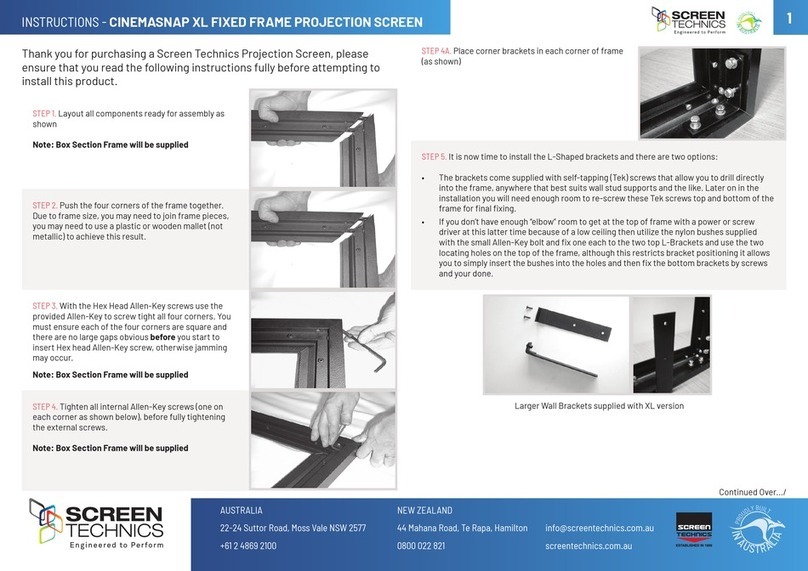
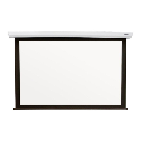
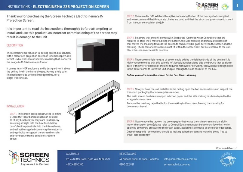
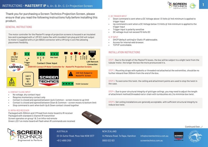
Screen Technics ELECTRICINEMA User manual

ELECTRICINEMA Connect IP Projection Screen
All inputs on module 1 are accessed by removing right hand end cap of screen canister
1. Contact Close Input
a. Contact Close Input for local control
b. Requires 2 x Momentary contacts duration minimum 50 milliseconds
c. Dedicated contact for Up & Down
d. Stop command is close opposite travel contact or both Up & Down together
2. DC Trigger Input
a. Down command is sent when a DC Voltage of 3 Volts @ 1mA minimum is applied to input, a
Up command is sent
b. Up command is sent when a DC Voltage of less than 1.0 Volts DC @ 1mA is applied to input, a
Down command is sent
c. Maximum cable length 75 meters approximately based 24 AWG gauge cable

3. Connect Network
a. Connect Network uses a RJ11 6P6C Plug 6 core wired straight through
b. 50 Meter maximum cable length between modules
c. Connect network carries commands when connected to other Connect Modules
d. Maximum of 8 Modules Total, including Connect IP module
4. Infra-Red Input
a. Supplied with 2 channel IR transmitter
b. Supplied with IR receiver with 300mm and 1.2M input lead
c. IR operates on Group 1 & 2 as standard
5. RJ45 LAN Input
a. DHCP or Static IP addressable
b. Internal Web Browser
c. TCP/IP controllable
6. PC or Mac Connect Software
a. As the module is DHCP default, this software will allow simple operation and identification of
IP address and port number of IP connect modules on network
b. PC Connect software will search for Connect IP Modules on the network
c. Screen shot below showing module, IP address using PC Connect
d. Connect to module

e. Screen shot of module connected
f. Allows operation of module via simple control
g. When command is sent –string showing command, IP address, Port number and feedback
response is shown in the box below
h. Click on Browser button and simple control
screen appears
i. Click on login to view advanced settings page

7. Connect Internal Web Browser
a. Using web browser
b. Type IP address as shown in PC Connect Software
c. Connect Login screen will be shown
d. Input User Name : Admin
e. Password : Connect
8. Connect Internal Web Browser
a. Select Direct Control from Control Menu
b. Direct Control Screen shown below
c. Partial 1 & 2 act as stop command unless partial has been programmed
d. MAF address and Module ID shown
e. Simple control feature
f. Status indication of screen –use refresh to obtain latest status update

9. Group Control
a. Direct Control Screens that have been programmed with the same IR group or switch group
(contact Close input)
b. Partial 1 & 2 act as stop command unless partial has been programmed
c. Simple control feature

10. IP Control Settings
a. Access settings via set up tab
b. Setting of static IP address
c. Mac address set up (If replacing on network)
d. Current IP operating parameters

e. AMX Discoverable enable
f. Screen Technics Beacon
g. Simple control page

11.Register settings
a. Access this menu by selecting System then Module Settings
b. Select MAF address or Module ID and select load
c. Change value and select update
d. This menu will enable changes of features within the module
e. 127 registers in total
f. Screen shot below showing register page

12.Infra-Red Group Bitmap calculator
a. Add the value of IR groups
b. If you wish the module to operate on Group 1 only –change register 75 to a value of 2
c. If you wish the module to operate on Group 1 & 2 only –change register 75 to a value of 6
Commonly Used
Registers
Register Number
65
Operation PIN
66
Programming PIN
67
Partial Pos 1 –Lo
68
Partial Pos 1 –Hi
69
Partial Pos 2 –Lo
70
Partial Pos 2 –Hi
71
SWITCH MODE
72
Partial 1 Open Mode
73
Partial 2 Open Mode
74
SWITCH GROUP Bitmapped
Register below
75
IR GROUP Bitmap Register
Below
76
Timer Up
77
Timer Down
78
MODULE_ID
82
Time_delay_up (100mS)
83
Time_delay_down (100mS)

13. Contact Close Switch Groups
a. Add the value of switch groups
b. If you wish the module to operate on Switch Group 1 only –change register 74 to a value of 2
c. If you wish the module to operate on Group 1 & 2 only –change register 74 to a value of 6
GROUP
VALUE
1
2
2
4
3
8
4
16
5
32
6
64
7
128
8
256
9
512
TOTAL
GROUP
VALUE
1
2
2
4
3
8
4
16
5
32
6
64
7
128
8
256
9
512
TOTAL

Switch Group Bitmap Register
Calculate the register number by using following table:-
Transfer the Value for each required group to the right column.
The Total of the values in the right column then becomes the Register
Value
Eg to set groups 1, 2 & 4 then the Total value is 22.
GROUP
VALUE
1
2
2
4
3
8
4
16
5
32
6
64
7
128
8
256
9
512
TOTAL

14.IP Connect Serial Protocol
a. This serial command protocol is essentially the same for all console channels
(a) TELNET via TCP/IP (2 ports 3001)
(b) HTTP via port 80
FORMAT
The stream is made up of messages. A message consists of 1 to 80 printable ascii characters followed by
and end of message. An end of message is one or more of CR and LF optionally combined with any
number of delimiters.
A message is made up of unsigned numerical value fields in decimal format separated by one or more
delimeters. A delimiter is any single or combination of space, comma or tab.
Examples of valid messages to the IP Connect module are given below. All these messages have the
same meaning.
1,3,45<CR>
1,3,45<LF>
1,3,45<CR><LF>
,1,3,45<CR><LF>
1,3,45,<CR><LF>
1,3,,45,<CR><LF>
1,3, 45,<CR><LF>
1,3,45,<CR>, ,<LF>
01,3,45<CR><LF>
000000001,3,45<CR><LF>
1 3 45<CR><LF>
1, 3, 45<CR><LF>
A message is not a valid message if
It contains more than 80 characters before an end of message character is received.
It contains a character that is not <CR>,<LF>,<TAB>,<SPACE>,0,1,2,3,4,5,6,7,8,9,”,”.
A numerical field exceeds 65535
It contains more than 10 fields
If a packet is determined to be not a valid message it is ignored. If a message is determined to be
invalid before the end of message is ignored then all characters received are ignored until an end of
message character is received.
Messages from the IP Connect module comply with the requirements of the incoming messages but in
addition are fixed width formatted. Each numerical field is made of 5 characters (leading spaces and
digits). A comma delimiter is included. An Example is shown below.
1, 3, 45<CR><LF>

15.CONTROL COMMANDS
a. These commands are used to control the operaon of screens.
b. The Switch groups and IR groups must be programmed according to secon 5
c. Unified address is MAF address plus 16 e.g. Module 1 is Unified address 17
Operate Module Direct
COMMAND Value Descripon
30 Module ID Operate Module UP
31 Module ID Operate Module PARTIAL 1
32 Module ID Operate Module PARTIAL 2
33 Module ID Operate Module DOWN
36 Module ID Operate Module STOP
d. Command followed by value 0operates all modules connected via Connect Network
including the Connect IP module
(e.g.: 30 0 will operate all devices connected via the Connect network)
e. Example of direct command
Connected to 192.168.0.32:3001 – command30 1 using module ID would see the screen
move to up posion
IR Group Commands
f. IR group control can be used to control screens directly if connected via Connect Network
including the Connect IP module
g. Each module will require programming via register 75, as per point 11 in document
h. Example of direct command
Connected to 192.168.0.32:3001 – command20 1 ,would see all screens programmed to
operate on IR group 1 move to up posion
i. Command followed by value 0 operates all modules connected via Connect Network
including the Connect IP module

Operate IR Group
Command IR Group Descripon
20 IR Group 1 to 9, 0 Operate IR Group UP
21 IR Group 1 to 9, 0
Operate IR Group PARTIAL 1
22 IR Group 1 to 9, 0
Operate IR Group PARTIAL 2
23 IR Group 1 to 9, 0
Operate IR Group DOWN
26 IR Group 1 to 9, 0
Operate IR Group STOP
Switch Group Commands
a. Switch group control can be used to control screens directly if connected via Connect
Network including the Connect IP module
b. Each module will require programming via register 74, as per point 11 in document
c. Example of direct command
Connected to 192.168.0.32:3001 – command20 1 - would see all screens programmed to
operate on Switch group 1 move to up posion
d. Command followed by value 0 operates all modules connected via Connect Network
including the Connect IP module
Operate Switch Group
Command Switch Group Descripon
10 SWITCH Group 1 to 9, 0 Operate Switch Group UP
11 SWITCH Group 1 to 9, 0
Operate Switch Group PARTIAL 1
12 SWITCH Group 1 to 9, 0
Operate Switch Group PARTIAL 2
13 SWITCH Group 1 to 9, 0
Operate Switch Group DOWN
16.Programming Partial Positions 1 & 2
a. Before paral posions can be programmed, the screen must be calibrated – Calibraon is
done by sending the below command. eg. to calibrate screen 1 a code of 192.168.0.32:3001
– command 042 17using Unified address would see the screen calibrate
b. Calibraon command can also be sent from the PC Connect soware
Command
MAF Address + 16
Value 1
42
Unified Address
3781

c. Please start calibraon by returning screen to top limit and then sending calibraon
command.
d. Due to motor run me this feature is not available on some large projecon screens or
Screen Lowering devices
e. Paral 1 must be set first and must be above paral 2
f. Note that if paral posions have been programmed Stop 1 and Stop 2 on infra red
transmier will send screen to paral 1 & 2, and will not stop the screen.
Setting the Partial positions
Note: Partial posi tions are set using internal timers, position can vary due to mains voltage
uctuations, motor load changes and temperature.
a. To set Paral 1 – stop screen at required locaon and send command - if screen 1 is being used
a IP address 192.168.0.32:3001 – command 044 17 using unified address would see the
screen set paral posion 1
b. To set Paral 2 – stop screen at required locaon and send command - if screen 1 is being used
a IP address 192.168.0.32:3001 – command 045 17 using unified address would see the
screen set paral posion 1
17.Module Status Feedback
A module status buffer (20 record FIFO) is updated as a automacally generated Send Register
Commands with register number = 0x20 are sent from each module.
The module status buffer contains the Module ID (1 byte), and Module Status (2 bytes)
Command
050
Response from module e.g. 150, 1, 1, 6 – value 6 indicates screen at top
Command Value 1 Value 2 Value 3
150 Status Module ID Module Status Register (0x20)
COMMAND MAF Address + 16 Value 1 Descripon
44 Unified Address 3781 Sets Paral Posion 1
45 Unified Address 3781 Sets Paral Posion 2

Note –Status=1 is returned if valid data and no further records in the status buffer
Status=2 is returned if valid data and there are still records in status buffer
Status=3 is returned if valid data but the buffer is full (eg may have lost data)
Status=6 is returned if there are no new records
This buffer is updated when screens are moved. It is also updated automatically every 60 seconds.
It needs to be polled regularly to clear the stored data otherwise it will get full and records will be
lost. Even though screens may not be moving the data is being updated even though the status is the
same
Example of string from module
192.168.0.32 3001 Up Send 30 1
192.168.0.32 3001 Up Receive 130, 1, 1
192.168.0.32 3001 Status Change Receive 9999
192.168.0.32 3001 Get Module Status Send 67 3781
192.168.0.32 3001 Get Module Status Receive 167, 0, 255, 255, 255, 255, 255, 255, 255, 255
192.168.0.32 3001 Status Change Receive 9999
192.168.0.32 3001 Get Module Status Send 67 3781
192.168.0.32 3001 Get Module Status Receive 167, 6, 255, 255, 255, 255, 255, 255, 255, 255
Response Type No
Connect IP Module
0
Moving top
1
Moving bot
2
Moving PP1
3
Moving PP2
4
Moving PPT
5
Moving PPB
6
At TOP
7
At BOTTOM
8
At PP1
9
At PP2
10
Stopped manual
11
Error
12
Spare
13
Fail-timeout
14
Fail –current
15
Rattle
16
At PPT
17
At PPB

18.AMX Device Discovery
a. This feature allows the IP CONNECT module to be identified by AMX AV Control Systems.
When polled the IP CONNECT module responds with a Beacon message which contains
device specific information. (Eg Make, Model, Version)
With this information the AMX system is able to then configure itself with the correct
protocol to be able to control the IP Connect Module.
b. The protocol works for any of the Serial ports, and over TCP/IP.
c. The AMX “Device Discovery White Paper.Doc” defines, The Dynamic Device Discovery
Protocol - the connection methods and data interactions required to dynamically connect a
third party device to a NetLinx Master via either serial or IP connectivity.
d. AMX Discovery is enabled using Register 80 or via internal web browser
19. Factory Reset Switch
a. Single long press for 5 seconds approximately
Factory Default Mode selected.
LED double flashes.
Pressing button again exits mode.
Receiving an IR command exits this mode.
b. Single short press for 3 seconds approximately
Screen Rattle command.
3 seconds down 1 second up.
LED single flashes while in this function.
Pressing button again stops screen.
Function is exited when screen operation finished or
another screen operate command is acted on.
c. Double short press for 2 seconds approximately per
button press
Screen Up command. Screen travels to up limit.
LED single flashes while in this function. Pressing
button again stops screen. Function is exited when
screen travels to up position or another screen
operate command is sent.
d. Triple short press for 2 seconds approximately per button press
Screen Down command. Screen travels to down limit.
LED single flashes while in this function.
Pressing button again stops screen.
Function also exited when screen operation finished or another screen operate command is
acted on.

20.Default IP Address when in Factory Default Mode
a. Hold reset button on module until LED flashes twice to put the IP module into static
IP mode
b. You will need to set your network adaptor
to look for IP range –example shown
c. Default IP address is 192.168.1.254
http://192.168.1.254
Into browser address bar
Input User
Name : Admin - Password : Connect
You should now see the direct control
screen
You can now access the settings for
the Connect IP module

Limit Setting for Connect ElectriCinema IP Screens
The following instructions are for the adjustment of the limit switches that alter the upper
and lower stop positions on "Connect" ElectriCinema IP Screens only
Where are The Limit Switches?
(On the Left Hand Side).
One switch is accessible through the slat rod opening and the other is behind a rubber grommet
towards the front of the canister.
Which Switch is for Up and Down?
Down switch - Accessible through the rubber grommet
Up switch - Accessible through the slat rod opening
What Tools do I Need?
Either the limit setting tool (supplied), a narrow tip screw driver (less than 4mm) or a 4mm Allen Key
Which Way do I Turn the Switch?
Clockwise always increases the amount of rotation (travel) of the motor.
Anti-clockwise always reduces the amount of rotation (travel) of the motor.
So pick the switch responsible for the limit position, up or down. Clockwise turning of the switch will
always let the motor travel further in that direction. Anti-clockwise turning of the switch will lessen the
amount of travel in that direction.
Can I adjust the switch while the screen is sitting on the limit - ie fully up or down?
Clockwise adjustment? –YES. But it is better to back the screen away from the limit and then adjust
Anti-clockwise adjustment? - NO you will damage the micro switch if you turn it anti-clockwise while the
screen is sitting on the limit. Never attempt this. You must back the screen away from the limit
before adjustment. After adjustment you will need to run the screen up and down to pick up the new
limit
Will I void the product warranty if I damage the screen whilst making these adjustments?
Yes.!!!
Should you have any questions regarding the installation of our products
please call our sales desk on +61 2 4869 2100 for assistance
Screen Technics Pty Ltd
Cnr Vale & Suttor Roads, Moss Vale, NSW 2577
Ph: +62 2 4869 2100 Fx: +62 2 4869 2123
Thinking Screens ….. Think Screen Technics
Other manuals for ELECTRICINEMA
4
Table of contents
Other Screen Technics Projection Screen manuals

Screen Technics
Screen Technics ELECTRICINEMA 235 Guide

Screen Technics
Screen Technics ELECTRICINEMA A User manual

Screen Technics
Screen Technics MASTERFIT IP User manual

Screen Technics
Screen Technics CINEMASNAP 235 User manual

Screen Technics
Screen Technics CINEMASNAP XL User manual

Screen Technics
Screen Technics CINEMATECH User manual

Screen Technics
Screen Technics ELECTRICINEMA User manual

Screen Technics
Screen Technics ELECTRICINEMA A User manual
Screen Technics
Screen Technics TRAPDOOR User manual

Screen Technics
Screen Technics ELECTRICINEMA 235 User manual