AR-5520 SPECIFICATIONS 3-1
[3] SPECIFICATIONS
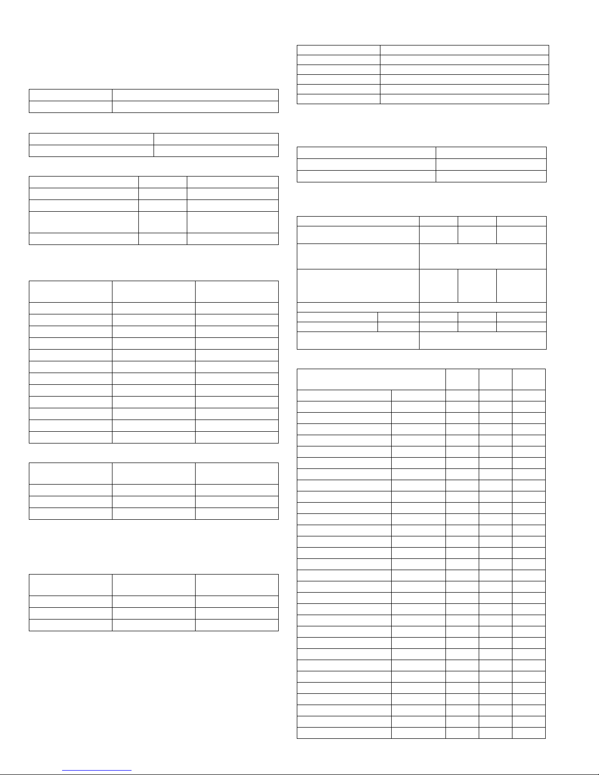
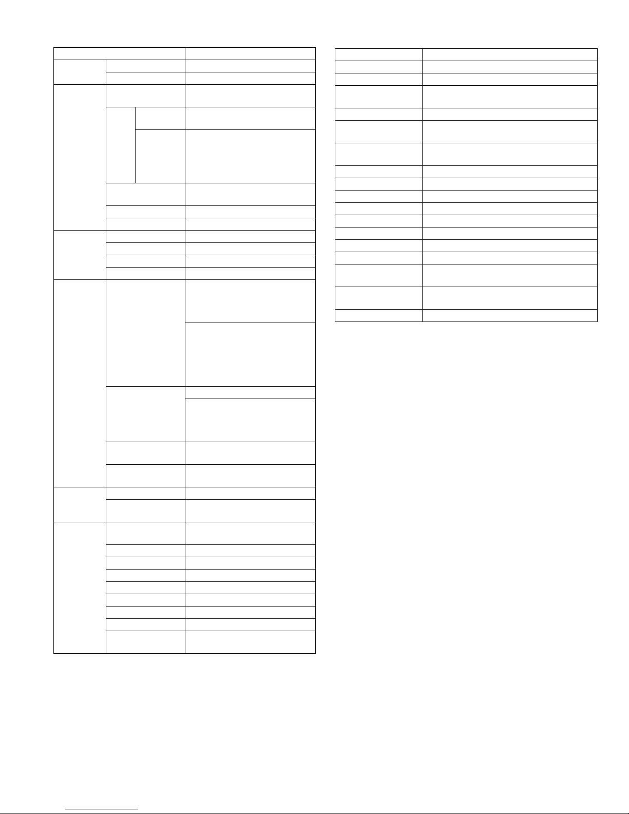
1. Copy mode
A. Type
B. Machine composition
(1) Option
C. Copy speed
(1) Engine speed (ppm)
(2) Document replacement speed (Copy mode)
S to S : Tray1 A4/8.5”X11” document 11 sheets (11 pages), copy 1 set
S to D : Tray1 A4/8.5”X11” document 22 sheets (22 pages), copy 1 set
D to D : Tray1 A4/8.5”X11” document 11 sheets (22 pages), copy 1 set
(3) Job efficiency
S to S : Tray1 A4/8.5”X11” document 10 sheets (10 pages), copy 5 sets
S to D : Tray1 A4/8.5”X11” document 10 sheets (10 pages), copy 5 sets
D to D : Tray1 A4/8.5”X11” document 10 sheets (20 pages), copy 5 sets
(4) First copy time
600x300dpi, AE mode, A4/Letter, single surface copy with OC, in polygon
ready state
D. Document
E. Paper feed
(1) Paper feed section details
(2) Feedable paper
Type Desk-top
Paper exit Wing less
AR-5516 / AR-5516S / AR-5516D 16-CPM multi function model
AR-5520 / AR-5520S / AR-5520D 20-CPM multi function model
Machine Model
250 sheets paper feed unit AR-D34
250 sheets x 2 paper feed unit AR-D35
SPF AR-SP10 AR-5520/ AR-5520S
AR-5516 /AR-5516S
RSPF AR-RP10 AR-5520D/ AR-5516D
Paper size AR-5520 / AR-5520S
AR-5520D
AR-5516 / AR-5516S
AR-5516D
A4/ 8.5”x11” 20ppm 16ppm
A4R 14ppm 12ppm
8.5”x11”R 15ppm 12ppm
A5/ 5.5”x8.5” 20ppm 16ppm
B5/ 16K 20ppm 16ppm
B5R 16ppm 14ppm
16KR 15ppm 14ppm
8.5x13” 12ppm 11ppm
B4/ 8.5”x14 12ppm 10ppm
A3 11ppm 9ppm
11”x17” 10ppm 9ppm
8K 11ppm 10ppm
Copy mode AR-5520 / AR-5520S
AR-5520D
AR-5516 / AR-5516S
AR-5516D
S to S 20cpm (100%) 16cpm (100%)
S to D 9cpm (45%) 9cpm (56%)
D to D 8cpm (40%) 8cpm (50%)
Copy mode AR-5520 / AR-5520S
AR-5520D
AR-5516 / AR-5516S
AR-5516D
S to S 19cpm (95%) 15cpm (94%)
S to D 11cpm (55%) 10cpm (63%)
D to D 10cpm (50%) 10cpm (63%)
Tray Content
1st tray 7.2 sec or less
2nd tray 8.5 sec or less
3rd tray 9.5 sec or less
4th tray 10.5 sec or less
Bypass tray 7.5 sec or less
Max. document size A3, 11" X 17"
Document reference position Left side center
Detection (Platen) None
Item 1st tray 2nd tray
Bypass tray
Paper capacity 250
sheets 250
sheets 100 sheets
Paper size detection No
(Paper size is set with
the system setting.)
Paper type setting No No No
(Heavy
paper setting
is enabled.)
Paper size changing method The paper guide is set by the user.
Paper when shipping AB series A4 A4 -
Size setting Inch series
8 1/2” x11” 8 1/2” x11”
-
Remaining paper quantity
detection Only empty detection available
Paper size 1st tray 2nd tray Bypass
tray
A3 297x420 Ye s Ye s Ye s
B4 257x364 Ye s Ye s Ye s
A4 297x210 Ye s Ye s Ye s
A4-R 210x297 Yes Ye s Yes
B5 257x182 Ye s Ye s Ye s
B5R 182x257 Ye s Yes Yes
A5 210x148.5 Ye s N/A Yes
A5R 148.5x210 N/A N/A Yes
A6R 105x148.5 N/A N/A Yes
B6R 128.5x182 N/A N/A Yes
Ledger 11 x 17 in 279.4x431.8 Ye s Ye s Ye s
Legal 8.5x14in. 215.9x355.6 Ye s Ye s Ye s
Foolscap 8.5 x 13 in 215.9x330.2 Ye s Ye s Ye s
Letter 11x8.5in 279.4x215.9 Ye s Ye s Ye s
Letter-R 8.5x11in 215.9x279.4 Ye s Ye s Ye s
Executive-R 7.25x10.5in. 184.2x266.7 N/A N/A Yes
Invoice 8.5x5.5 in. 215.9x139.7 Ye s N/A Yes
Invoice-R 5.5x8.5 in 139.7x215.9 N/A N/A Yes
8K 270x390 Ye s Ye s Ye s
16K 270x195 Ye s Ye s Ye s
16KR 195x270 Ye s Ye s Ye s
COM10 104.8x241.3 N/A N/A Ye s
COM9 98.4x225.4 N/A N/A Yes
C5 162x229 N/A N/A Yes
DL 110x220 N/A N/A Yes
Postcard 100x148 N/A N/A Yes
Return postcard 200x148 N/A N/A Yes
Long format No. 3 120.1x235 N/A N/A Yes
Monarch 98.4x190.5 N/A N/A Yes
Western format No. 2 114x162 N/A N/A Yes
Western format No. 4 105x235 N/A N/A Yes