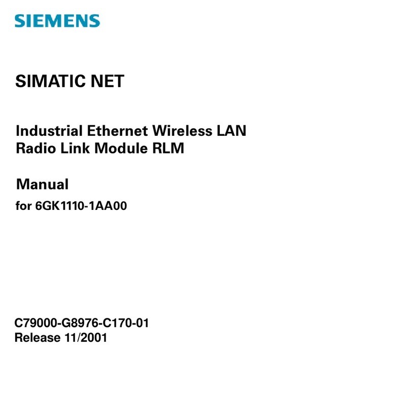
Siemens SINAMICS V60 User manual
Other Siemens Control Unit manuals

Siemens
Siemens Simatic S7-1500 User manual

Siemens
Siemens SIMATIC ET 200SP User manual
Siemens
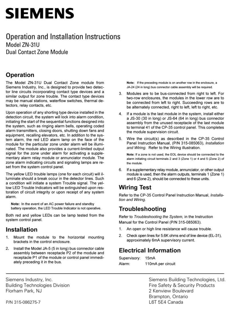
Siemens ZN-31U User manual
Siemens
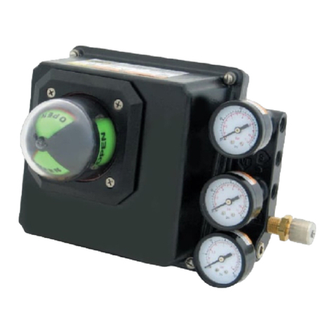
Siemens ValvePAC Series User manual
Siemens
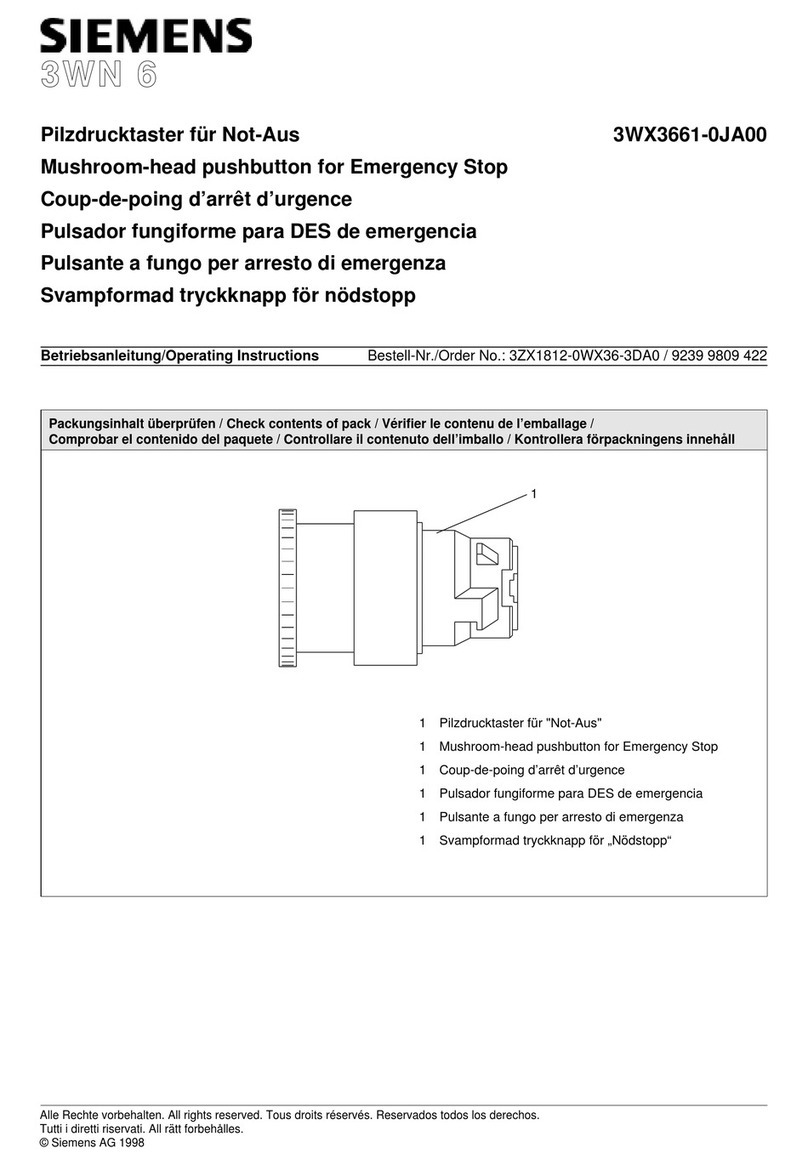
Siemens 3WN 6 3WX3661-0JA00 User manual
Siemens
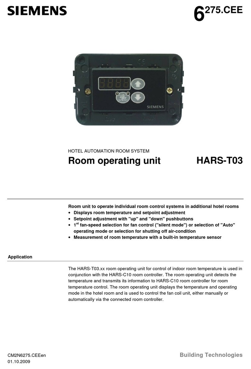
Siemens HARS-T03 Series User manual
Siemens
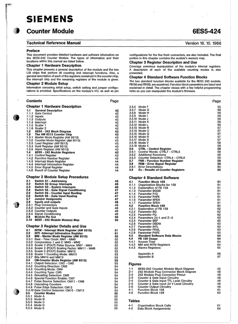
Siemens 6ES5-424 Product manual
Siemens
Siemens SIMATIC 6ES7135-4MB02-0AB0 User manual
Siemens
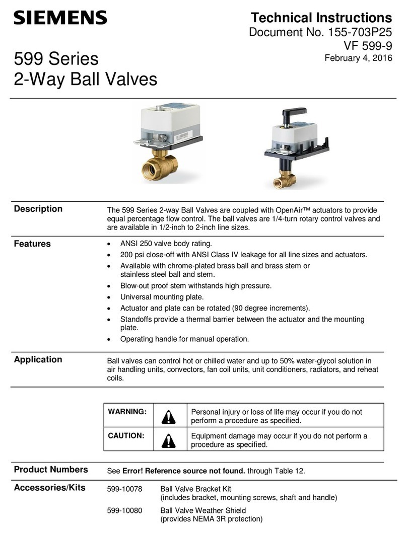
Siemens Flowrite 599 Series Owner's manual
Siemens
Siemens AP 641 Service manual
Siemens
Siemens 3VL9800-3MJ00 User manual
Siemens
Siemens HOTEL SOLUTION HTC3.1/A User manual

Siemens
Siemens SINUMERIK 840D sl Instruction sheet

Siemens
Siemens SINAMICS S120 User manual
Siemens
Siemens LMV36.520A1 Operator's manual
Siemens
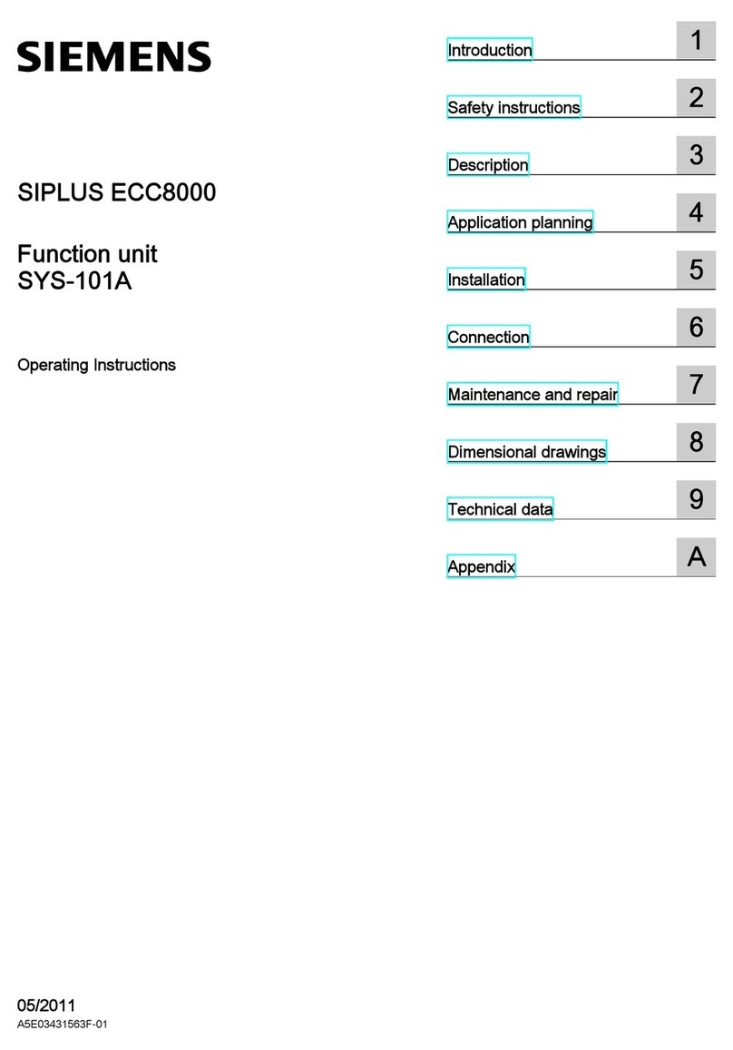
Siemens SIPLUS ECC8000 User manual
Siemens
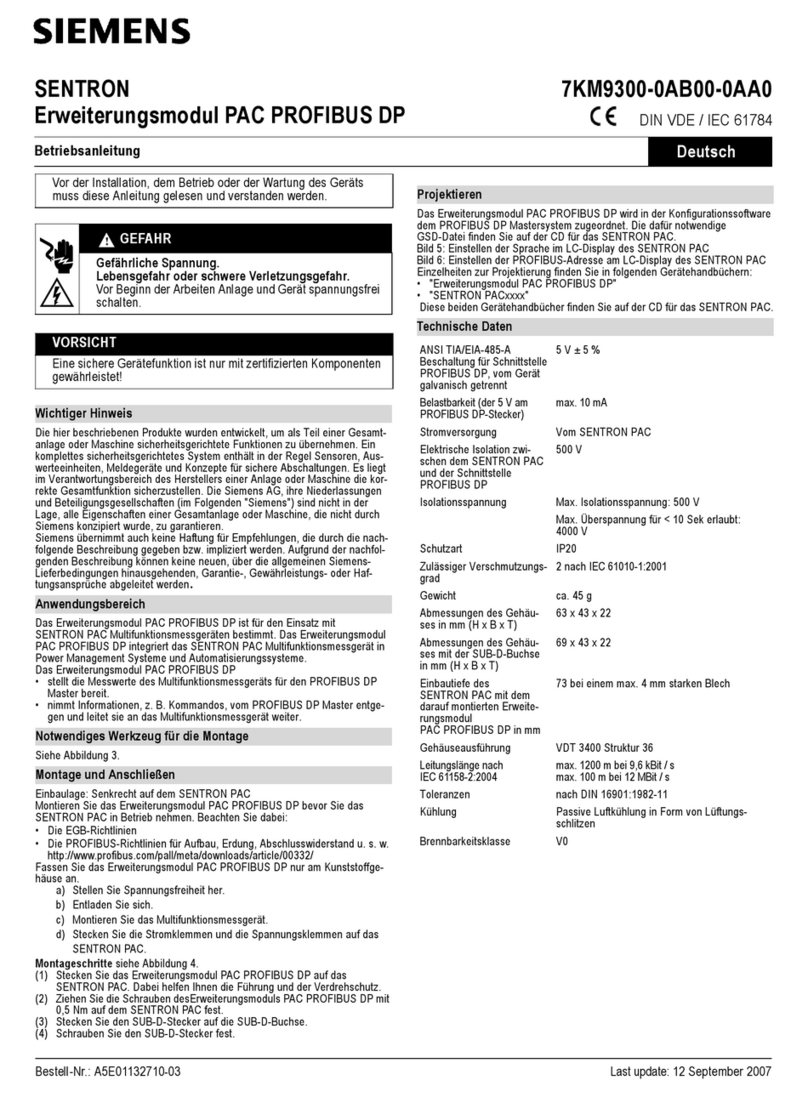
Siemens SENTRON PAC PROFIBUS DP User manual
Siemens
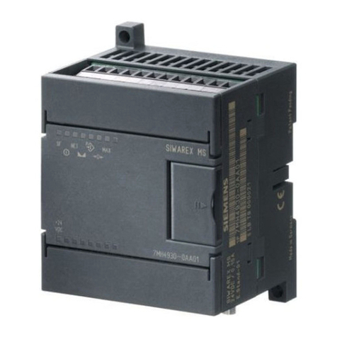
Siemens SIWAREX MS User manual

Siemens
Siemens SINAMICS G130 User manual
Siemens
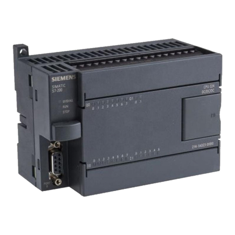
Siemens SIMATIC S7 User manual
Popular Control Unit manuals by other brands

Festo
Festo Compact Performance CP-FB6-E Brief description

Elo TouchSystems
Elo TouchSystems DMS-SA19P-EXTME Quick installation guide

JS Automation
JS Automation MPC3034A user manual

JAUDT
JAUDT SW GII 6406 Series Translation of the original operating instructions

Spektrum
Spektrum Air Module System manual

BOC Edwards
BOC Edwards Q Series instruction manual

KHADAS
KHADAS BT Magic quick start

Etherma
Etherma eNEXHO-IL Assembly and operating instructions

PMFoundations
PMFoundations Attenuverter Assembly guide

GEA
GEA VARIVENT Operating instruction

Walther Systemtechnik
Walther Systemtechnik VMS-05 Assembly instructions

Altronix
Altronix LINQ8PD Installation and programming manual


