manuals.online logo
Brands
  1. Home
  2. •
  3. Brands
  4. •
  5. Siemens
  6. •
  7. Controllers
  8. •
  9. Siemens instabus JB520C23 User manual

Siemens instabus JB520C23 User manual

P.T.O.
instabus
®
Technical Manual
Solar protection actuator
JB520C23
5WG1520-4CB23
April 2020 / Page 1
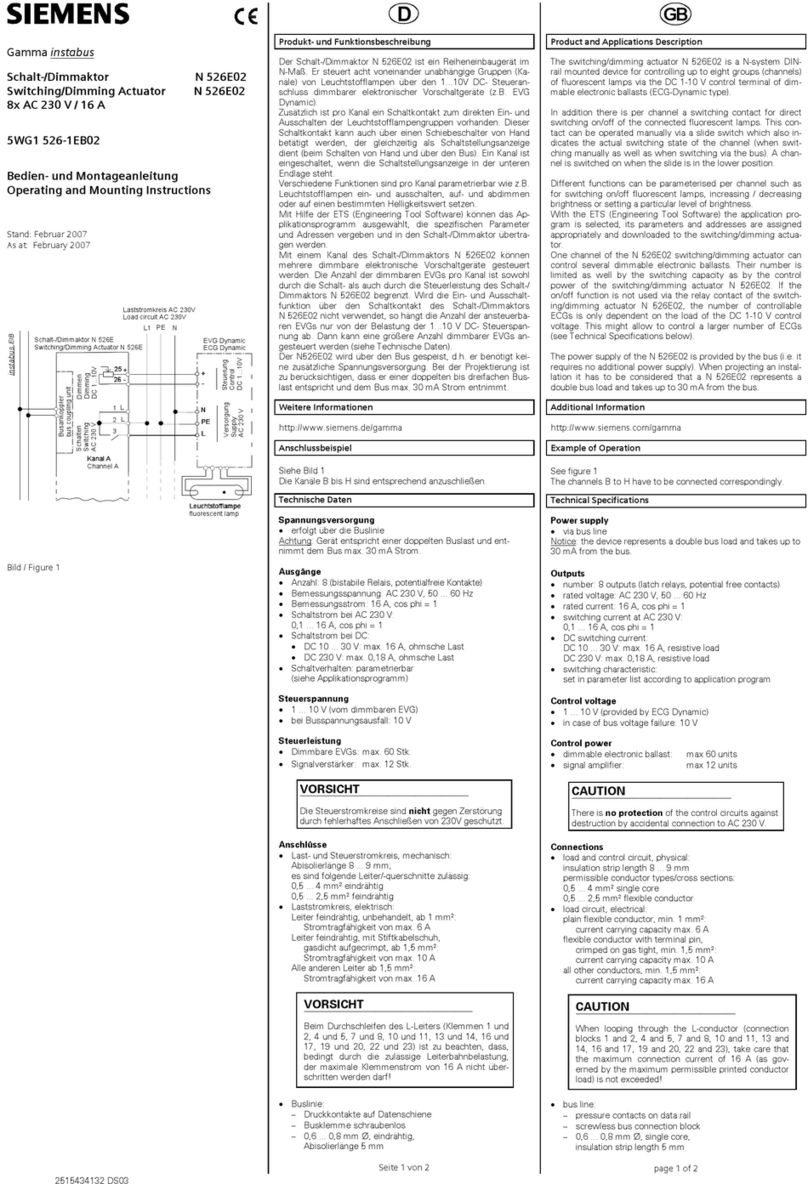
Product and Applications Description
The JB520C23 solar protection actuator is a KNX device with
one relay output. The device is installed in a 4 x 4 inch junc-
tion box. The bus is connected via a bus terminal block. The
actuator electronics are supplied via the bus voltage.
The JB520C23 may be used to control blinds, shutters, awn-
ings, windows, or doors.
The device is designed to drive (per channel) one AC 120V
drive (motor) with electromechanical limit switches or with
integrated electronics for disconnection at the limit positions.
For drives with electromechanical limit switches the actuator
can be configured to detect the status of the electromechan-
ical limit switches such that the travel time between the end
positions can be measured via a synchronization run. The
travel time of the blind / shutter is automatically measured
from the upper end position to the lower end position and
vice versa. The measurement is only reliable for drives with
electromechanical limit switches. The travel time cannot be
automatically adjusted for drives with integrated electronics
for disconnection at the limit positions. These drives have to
be controlled via a time limit. Their travel times have to be
manually measured as precisely as possible and configured in
the application program.
Parallel operation of several drives on one channel requires
using a special separation relay. If such a separation relay is
connected to the output to drive several drives in parallel,
then the travel time has to be configured manually.
If the device is configured for automatic detection of the
travel time, then parallel operation of several drives with elec-
tromechanical limit switches or mixed operation with drives
with integrated electronics for disconnection at the limit po-
sitions is not permitted.
Application Program
The JB520C23 Solar protection actuator (JB module) needs
the application program
"07 B0 A1 Shutter Actuator 982A01“.
Example of Operation
K1
Down
Bus coupling unit
instabus KNX
Shutter / blind actuator JB520/23
K2
Up
Load circuit
AC V120
N PEL1
Up
Down
1
2
4 N
M
1~
Venetian
blind motor
3 L
Detection
of end
position
Channel A
Technical Specifications
Power supply
•via the bus line
•KNX bus voltage:
DC 24V (DC 21...30V) via KNX/EIB bus line
•KNX bus current: < 10 mA
Outputs
•Mains connection:
carried out via the terminals for L and N of the actuator
•1 drive channel with 2 relay contact outputs,
- rated voltage: AC 120 V, 50/60 Hz
•rated current: 6A (resistive load)
•switching current at DC 24 V:
-6 A resistive load,
-4 A inductive load (L/R = 7 ms)
Maximum load
6 A @ 120 Vac (General Purpose)
Control elements
1 learning button:
for switching between normal operating mode and
addressing mode
Display elements
1 red LED:
for monitoring bus voltage and for displaying normal
mode/addressing mode
Connections
•Bus line : Bus connection pins for connection of the
screwless bus terminal block (red-black) 0.6…0.8 mm
Ø single core, strip insulation 5mm
•Load circuit:
see Location and Function of Interface Elements
Physical specifications
•housing: plastic
•dimensions (L x W x D):
length : 70 mm (2.76 inch)
width : 90 mm (3.54 inch)
depth: 44.6 mm (1.76 inch)
•weight: approx 198 g
•fire load: approx. 5 MJ
•Installation: in a junction box (min. dimensions (L-W-D))
Length: 4 inch (101.6 mm)
Width: 4 inch (101.6 mm)
Depth: 2 inch (50.8 mm)
Electrical safety
•Degree of pollution (according to IEC 60664-1): 2
•Type of protection (according to EN 60529): IP 20
•Overvoltage category (according to IEC 60664-1): III
•Bus: safety extra low voltage SELV DC 24 V
•Device complies with: EN 50428
Electromagnetic compatibility
complies with EN 50428
Environmental specifications
•Ambient operating temperature:
- 5 … + 45 °C (+ 23 ... + 113 F)
•Storage temperature:
- 25 … + 70 °C (- 13 ... + 158 F)
•Relative humidity (not condensing): 5 % … 93 %
Reliability
•Failure rate: 632 fit at 40°C
Markings
EIB, KNX, UL
Listings and Certifications
CE mark
complies with the EMC regulations (residential and func-
tional buildings) and low voltage regulations
UL listed (E464611)
UL 916, Open Energy Management Equipment
USA
L1V30044675A RS-AC
instabus
®
Technical Manual
Solar protection actuator
JB520C23
5WG1520-4CB23
April 2020 / Page 2
Location and Function of the Interface Elements
A4
A5
A6
A7
A1
A2
A3
A7
A8
A9 A10
A11
A7
A3
A1 Type label (with space for physical address of the de-
vice)
A2 Identification number of the device
A3 Protective lid over bus connection
A4 Bus connection terminal block for single core conduc-
tors with 0.6...0.8 mm Ø
A5 LED for indicating normal operating mode (LED off) or
addressing mode (LED on); returns to normal operating
mode automatically after receiving the physical address
A6 Learning button for switching between normal operat-
ing mode and addressing mode for receiving the physi-
cal address
A7 1/2 inch screw nut
A8 Wire (red) Motor A up (AWG #14)
A9 Wire (yellow) Motor A down (AWG #14)
A10 Wire (black) Line (Hot) (AWG #14)
A11 Wire (white) Neutral (AWG #14)
Dimension Diagram
Dimensions in mm (inch)
(2.76) (2.76)
(3.54) (1.76)
.
B1 B4 B2 B1
B3
B1 B4 B2
B3
B1 4” x 4” Junction Box
B2 Device
B3 Bus connection pins of the module for connection of
the bus terminal block for single core conductors with
0.6…0.8 mm Ø
B4 1/2 inch screw nut
Mounting and Dismounting
•Mounting of a JB module:
Option 1 (mounting inside a J-Box)
- Insert the thread of the JB module (B2) into the 1/2 inch
knockout between two adjacent J-Boxes (B1)
- Fasten the JB module (B2) with the 1/2 inch thread nut (B4)
- Remove the protective lid (B3) and connect the bus wire to
the bus terminal block (A4)
- Connect the wires from the device to the field wires using
wire nuts (not provided in package)
Option 2 (mounting outside of a J-Box)
- Insert the thread of the JB module (B2) into the 1/2 inch
knockout of the J-Box (B1)
- Fasten the JB module (B2) with the 1/2 inch thread nut (B4)
to the J-Box (B1)
- Connect the bus wire to the bus terminal block under the
protective cover (B3)
- Connect the wires from the device to the field wires using
wire nuts (not provided in package)
•Assignment of the Physical Address:
- A short push (< 2 s) of learning button (A6) enables the ad-
dressing mode, which is indicated when the LED is continu-
ously on (A5). The device returns to normal operating mode
(LED Off) automatically after receiving the physical address or
if the learning button is pushed again.
- A very long push (> 20 s) of the learning button resets the
device to factory settings. This is indicated by constant flash-
ing for 8 seconds.
- A long push (> 5 s up to 20 s) of the learning button enables
the Connection Test for commissioning with Desigo. This
mode can be disabled by a short push any time.
- Install the protective lid (B3) and fasten with screws (pro-
vided in package)
•Dismounting a JB module:
- Disconnect power to the module
- Remove the wire nuts and bus connection
- Unfasten the 1/2 inch thread nut (B4) connecting the JB
module (B2) to the J-Box (B1)
- Remove the JB module (B2) from the J-Box (B1)
D2
D2.4
5 mm
D2
D2.4
25...35 mm D1
C2
C2.2 C2.1
C2.3
Wiring
Slipping off/on bus connection blocks
The bus connection block consists of two components (C2.1
and C2.2) with four terminal contacts each. Take care not to
damage the two test sockets (C2.3) by accidentally connect-
ing them to the bus cable or with the screw driver (e.g. when
attempting to unplug the bus connection block).
Slipping off bus connection blocks
- Carefully put the screw driver to the wire insertion slit of
the bus connection block’s grey component (C2.2) and
- pull the bus connection block (C2) from the module.
Note
Don’t try to remove the bus connection block from the bottom
side. There is a risk of shorting-out the device!
Slipping on bus connection blocks
- Slip the bus connection block (C2) onto the guide slot of
the module and
- press the bus connection block (C2) down to the stop.
Connecting and Disconnecting bus cables
Connecting bus cables
- The bus connection block (D2) can be used with single
core conductors Ø 0.6…0.8 mm.
- Remove approx. 5 mm of insulation from the conductor
(D1) and plug it into the bus connection block (D2)
(red = +, grey = -)
Disconnecting bus cables
- Unplug the bus connection block (D2) and remove the bus
cable conductor (D1) while simultaneously wiggling it.
Connecting mains and load circuit:
Connect wires
-Connect wire leads using wire nuts.
USA
Hazardous voltage.
Can cause death, or serious injury or property damage.
The device must not be opened.
A faulty device should be returned to the local Siemens sales office
or distributor.
WARNING
WARNING
The device must be mounted and commissioned by a factory trained person.
The prevailing safety rules must be observed!
Mount in dry locations only!
Electromagnetic compatibility
USA:
This device complies with part 15 of the FCC Rules. Op-
eration is subject to the following two conditions:
(1) This device may not cause harmful interference, and
(2) this device must accept any interference received, in-
cluding interference that may cause undesired operation.
This equipment has been tested and found to comply with
the limits for a Class B digital device, pursuant to part 15
of the FCC Rules. These limits are designed to provide
reasonable protection against harmful interference in a
residential installation. This equipment generates, uses
and can radiate radio frequency energy and, if not in-
stalled and used in accordance with the instructions, may
cause harmful interference to radio communications.
However, there is no guarantee that interference will not
occur in a particular installation. If this equipment does
cause harmful interference to radio or television recep-
tion, which can be determined by turning the equipment
off and on, the user is encouraged to try to correct the in-
terference by one or more of the following measures:
- Reorient or relocate the receiving antenna.
- Increase the separation between the equipment and
receiver.
- Connect the equipment into an outlet on a circuit
different from that to which the receiver is connected.
- Consult the dealer or an experienced radio/TV
technician for help.
This device complies with Part 15 of the FCC rules.
Changes or modifications not expressly approved by Sie-
mens Schweiz AG could void the user’s authority to oper-
ate the equipment.
United States representative:
https://new.siemens.com/us/en/products/buildingtechnol-
ogies/home.html
Canada:
CAN ICES-3(B)/NMB-3(B)
This manual suits for next models

1

Other Siemens Controllers manuals

Siemens ST750 User manual

Siemens

Siemens ST750 User manual

Siemens Synco 700 User manual

Siemens

Siemens Synco 700 User manual

Siemens GEB-1E Series User manual

Siemens

Siemens GEB-1E Series User manual

Siemens SIMOTION D410-2DP/PN User manual

Siemens

Siemens SIMOTION D410-2DP/PN User manual

Siemens PXC Series User manual

Siemens

Siemens PXC Series User manual

Siemens 125-1957 User manual

Siemens

Siemens 125-1957 User manual

Siemens Types NRK 16-T../A User manual

Siemens

Siemens Types NRK 16-T../A User manual

Siemens S7-1200 TELECONTROL User manual

Siemens

Siemens S7-1200 TELECONTROL User manual

Siemens SINUMERIK 840D sl User manual

Siemens

Siemens SINUMERIK 840D sl User manual

Siemens Climatix POL822 User manual

Siemens

Siemens Climatix POL822 User manual

Siemens N 605D41 User manual

Siemens

Siemens N 605D41 User manual

Siemens Simatic S7-1500 User guide

Siemens

Siemens Simatic S7-1500 User guide

Siemens G2540 Series User manual

Siemens

Siemens G2540 Series User manual

Siemens SKP25 Series Owner's manual

Siemens

Siemens SKP25 Series Owner's manual

Siemens SIRIUS 3RT203 S Series User manual

Siemens

Siemens SIRIUS 3RT203 S Series User manual

Siemens PXC Series User manual

Siemens

Siemens PXC Series User manual

Siemens SINAMICS V90 PROFINET User guide

Siemens

Siemens SINAMICS V90 PROFINET User guide

Siemens OpenAir GBB Series Installation guide

Siemens

Siemens OpenAir GBB Series Installation guide

Siemens ESP200 User manual

Siemens

Siemens ESP200 User manual

Siemens SIRIUS 3RW5 series Technical Document

Siemens

Siemens SIRIUS 3RW5 series Technical Document

Siemens SIRIUS 3SX3217 User manual

Siemens

Siemens SIRIUS 3SX3217 User manual

Siemens SITRANS L Administrator guide

Siemens

Siemens SITRANS L Administrator guide

Siemens SIMATIC ET 200SP User guide

Siemens

Siemens SIMATIC ET 200SP User guide

Siemens SINUMERIK 808D User manual

Siemens

Siemens SINUMERIK 808D User manual

Popular Controllers manuals by other brands

Furious FPV Acrowhoop v2 Quick connect guide

Furious FPV

Furious FPV Acrowhoop v2 Quick connect guide

Emerson Dixell Wing XW570L Installing and operating instructions

Emerson

Emerson Dixell Wing XW570L Installing and operating instructions

m-Dimension D3208 user guide

m-Dimension

m-Dimension D3208 user guide

BWT Manager Connect Duo instruction manual

BWT

BWT Manager Connect Duo instruction manual

PRECISION DIGITAL ProVu PD6310 instruction manual

PRECISION DIGITAL

PRECISION DIGITAL ProVu PD6310 instruction manual

Vive Comfort TP-S-905 Operation manual

Vive Comfort

Vive Comfort TP-S-905 Operation manual

BBE MOVISTROB Series 2100 instruction manual

BBE

BBE MOVISTROB Series 2100 instruction manual

nilan Compact S CTS 602 installation guide

nilan

nilan Compact S CTS 602 installation guide

Naked NKD-pH Installation & start?up guide

Naked

Naked NKD-pH Installation & start?up guide

ccei Phileo VP operating instructions

ccei

ccei Phileo VP operating instructions

Kramer SL-1N quick start guide

Kramer

Kramer SL-1N quick start guide

Regulus UR1 A-DT Installation and operation manual

Regulus

Regulus UR1 A-DT Installation and operation manual

World Uniqueen EN-508 manual

World Uniqueen

World Uniqueen EN-508 manual

Dynamatic 4000 instruction sheet

Dynamatic

Dynamatic 4000 instruction sheet

Lawler 805 Installation & maintenance manual

Lawler

Lawler 805 Installation & maintenance manual

Minco 820B manual

Minco

Minco 820B manual

Paragon EC7000 Series General instructions

Paragon

Paragon EC7000 Series General instructions

PVR sub-zero NANOCHILL NC-110A user manual

PVR

PVR sub-zero NANOCHILL NC-110A user manual

manuals.online logo
manuals.online logoBrands
  • About & Mission
  • Contact us
  • Privacy Policy
  • Terms and Conditions

Copyright 2025 Manuals.Online. All Rights Reserved.