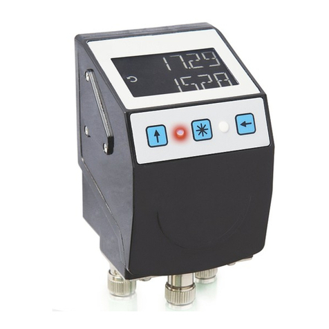
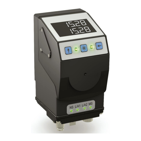
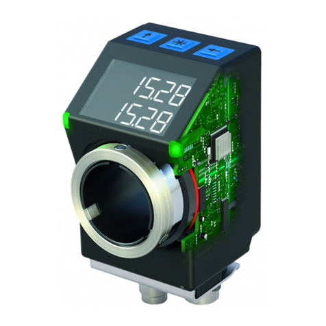
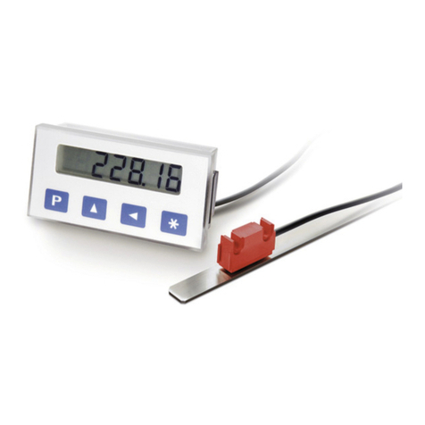
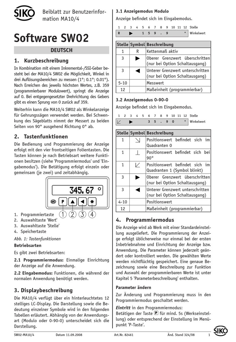
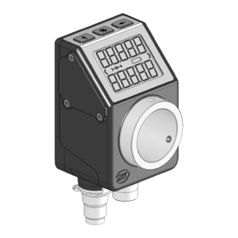
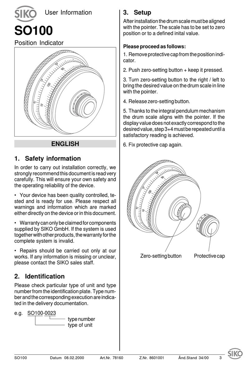
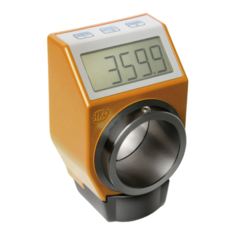
Siko AP20 User manual

134/19
AP20
Absolute Position Indicator
with interface
User manual

AP20 Date: 16.05.2019 Art. No. 89948 Mod. status 134/19 Page 2 of 76
Table of contents
1General Information .................................................................................................. 6
1.1 Documentation ........................................................................................................6
1.2 Definitions ..............................................................................................................6
1.3 Intended use ...........................................................................................................6
1.4 Switching on the operating voltage.............................................................................7
2Display and control keys ............................................................................................ 7
2.1 General ...................................................................................................................7
2.2 LCD display..............................................................................................................7
2.2.1 Extended display range ..........................................................................................8
2.3 LED display..............................................................................................................8
2.3.1 Positioning status.................................................................................................8
2.3.1.1 Device status LED1, LED2....................................................................................8
2.3.2 Ethernet module status..........................................................................................9
2.3.2.1 Network status LED3 ..........................................................................................9
2.3.2.2 Link/Activity LED4, LED5 ....................................................................................9
2.3.2.3 Module status LED6............................................................................................9
2.4 Control keys.............................................................................................................9
3Functional Description ............................................................................................. 10
3.1 Operating modes ....................................................................................................10
3.1.1 Position-bound operating modes...........................................................................10
3.1.1.1 Target window ................................................................................................11
3.1.1.2 Directional arrows............................................................................................12
3.1.1.3 LED display.....................................................................................................12
3.1.1.4 Loop positioning .............................................................................................12
3.1.2 Control word: Position-dependent operating modes .................................................13
3.1.3 Status word: Position-dependent operating modes...................................................14
3.1.4 Alpha-numeric display operating mode...................................................................15
3.1.5 Control word: Alpha-numeric display operating mode ...............................................15
3.1.6 Status word: Alpha-numeric display operating mode.................................................16
3.2 Battery buffering....................................................................................................17
3.3 Parameterization of the position indicator .................................................................18
3.3.1 Manual parameterization......................................................................................18
3.3.1.1 Starting parameterization .................................................................................18
3.3.1.2 Value input.....................................................................................................18
3.3.1.3 Value selection................................................................................................18
3.3.1.4 Overview of the operating menu ........................................................................19
3.3.1.5 "Changeable parameters" menu .........................................................................20
3.3.1.6 Quick Setup ....................................................................................................20
3.3.1.7 PROFINET .......................................................................................................21
3.3.1.8 Positioning.....................................................................................................21
3.3.1.9 Visualization...................................................................................................22

AP20 Date: 16.05.2019 Art. No. 89948 Mod. status 134/19 Page 3 of 76
3.3.1.10 LED function...................................................................................................22
3.3.1.11 Device options ................................................................................................22
3.3.2 Parameterization via interface ..............................................................................23
3.4 Calibration ............................................................................................................23
3.5 Additional functions ...............................................................................................23
3.5.1 Device data........................................................................................................23
3.5.2 Diagnosis...........................................................................................................24
3.5.2.1 Reading the error memories ..............................................................................24
3.5.2.2 Presentation ...................................................................................................24
3.5.3 Restore factory settings .......................................................................................25
3.6 Warnings / Errors....................................................................................................25
3.6.1 Warnings ...........................................................................................................25
3.6.2 Errors ................................................................................................................25
4Parameters.............................................................................................................. 27
4.1 Parameter overview.................................................................................................27
4.2 Positioning............................................................................................................29
4.2.1 Resolution .........................................................................................................29
4.2.2 Decimal Places....................................................................................................30
4.2.3 Counting Direction ..............................................................................................30
4.2.4 Calibration Value.................................................................................................31
4.2.5 Offset Application ...............................................................................................32
4.2.6 Target Window....................................................................................................32
4.2.7 Target Window Extended ......................................................................................33
4.2.8 Loop Type ..........................................................................................................33
4.2.9 Loop Length.......................................................................................................34
4.2.10 Control Word ......................................................................................................34
4.2.11 Status Word .......................................................................................................35
4.2.12 Target Value.......................................................................................................35
4.2.13 Actual Value.......................................................................................................36
4.2.14 Speed Value .......................................................................................................36
4.3 Visualization..........................................................................................................37
4.3.1 Display Orientation .............................................................................................37
4.3.2 Direction Indicators ............................................................................................37
4.3.3 Displayed Value 2nd Line .....................................................................................38
4.3.4 Target Window Extended Visualization ...................................................................38
4.3.5 Active Backlight White.........................................................................................39
4.3.6 Active Backlight Red ...........................................................................................40
4.3.7 Active Backlight Flashing .....................................................................................40
4.4 LEDs .....................................................................................................................41
4.4.1 LED1 Green Mode ................................................................................................41
4.4.2 LED1 Red Mode ...................................................................................................41
4.4.3 LED2 Green Mode ................................................................................................42
4.4.4 LED2 Red Mode ...................................................................................................43

AP20 Date: 16.05.2019 Art. No. 89948 Mod. status 134/19 Page 4 of 76
4.4.5 Active LED Flashing .............................................................................................43
4.5 Options.................................................................................................................44
4.5.1 Operating Mode ..................................................................................................44
4.5.2 Display Data.......................................................................................................44
4.5.3 Display String Mode.............................................................................................45
4.5.4 Display String1 ...................................................................................................46
4.5.5 Display String2 ...................................................................................................46
4.5.6 Difference Value..................................................................................................47
4.5.7 Difference Value Mode .........................................................................................47
4.5.8 Display Factor.....................................................................................................48
4.5.9 Display Divisor....................................................................................................49
4.5.10 Display Divisor Mode ...........................................................................................50
4.5.11 Key Enable Time..................................................................................................51
4.5.12 Key Configuration ...............................................................................................51
4.5.13 Key Calibration ...................................................................................................52
4.5.14 Key Incremental..................................................................................................52
4.5.15 Key Acknowledgment Mode...................................................................................53
4.5.16 PIN Change ........................................................................................................53
4.5.17 CODE Input ........................................................................................................54
4.5.18 Generic Mapping Parameter ..................................................................................55
4.5.19 System Configuration...........................................................................................55
4.5.20 Module Parameters ..............................................................................................57
4.5.21 System Command ................................................................................................57
4.6 Device information .................................................................................................57
4.6.1 Battery Voltage...................................................................................................57
4.6.2 Operation Voltage ...............................................................................................58
4.6.3 Temperature.......................................................................................................59
4.6.4 Actual Calibration Value.......................................................................................59
4.6.5 Software Version Application ................................................................................60
4.6.6 Software Version Ethernet Module .........................................................................60
4.6.7 Serial Number.....................................................................................................61
4.6.8 Production Date..................................................................................................61
4.6.9 MAC Address.......................................................................................................62
4.6.10 Device Identification...........................................................................................62
4.6.11 Generic Mapping Channel .....................................................................................63
4.7 Error Memory .........................................................................................................63
4.7.1 Error Count ........................................................................................................63
4.7.2 Error Number 1 ...................................................................................................64
4.7.3 Error Number 2 ...................................................................................................64
4.7.4 Error Number 3 ...................................................................................................65
4.7.5 Error Number 4 ...................................................................................................65
4.7.6 Error Number 5 ...................................................................................................66
4.7.7 Error Number 6 ...................................................................................................66
4.7.8 Error Number 7 ...................................................................................................67

AP20 Date: 16.05.2019 Art. No. 89948 Mod. status 134/19 Page 5 of 76
4.7.9 Error Number 8 ...................................................................................................67
4.7.10 Error Number 9 ...................................................................................................68
4.7.11 Error Number 10..................................................................................................68
4.7.12 Error Status........................................................................................................69
5PROFINET™.............................................................................................................. 69
5.1 Description............................................................................................................69
5.1.1 IP- Configuration ................................................................................................69
5.1.2 Cyclic data exchange (IO Data CR).........................................................................72
5.1.3 Acyclic data exchange (Record Data CR) .................................................................72
5.1.4 Operating modes and synchronization....................................................................72
5.1.5 Diagnostics alarms (Alarm CR)...............................................................................72
5.1.6 Behavior of the outputs .......................................................................................73
5.2 Commissioning aids ................................................................................................73
6Ethernet Functions .................................................................................................. 73
6.1 Web server.............................................................................................................73
6.2 FTP-Server .............................................................................................................74
6.3 Secure Host IP Configuration Protocol (Secure HICP) ...................................................75
7Block diagram ......................................................................................................... 75

General Information
AP20 Date: 16.05.2019 Art. No. 89948 Mod. status 134/19 Page 6 of 76
1General Information
1.1 Documentation
The following documents are associated with this document:
The data sheet describes the technical data, the dimensions, the pin assignment, the
accessories and the order key.
The installation instructions describe the mechanical and electrical installation with all
safety-relevant conditions and the associated technical specifications.
The User manual for actuator commissioning and integration into a fieldbus system.
You can also download these documents at http://www.siko-global.com/p/ap20.
Additional information and guidance regarding this device can also be found there.
1.2 Definitions
If not explicitly stated otherwise, decimal values are given as figures without an extension (e.
g. 1234), binary values are marked after the figure with a b (e. g. 1011b), hexadecimal values
with an h (e. g. 280h). Individual bits of larger logic units are named with their value after a
dot (e. g., CW.9; control word bit 9).
1.3 Intended use
For the further functional description, normal operation of the system with unchanged factory
setting is assumed unless otherwise described.
The present device is an absolute position indicator with integrated Industrial Ethernet
interface and a hollow shaft for direct shaft mounting. Indicators, control buttons and
interface are only active with external power supply. The sensor of measurement encoder
works magnetically incrementally. Without an external power supply, encoder changes are
recorded with battery support. The status of the replaceable battery is monitored. A volatile
target value can be displayed below the actual value via the backlit two-line LC display. A
direction display (indicator) is displayed if there is a deviation between the actual value and
the target window (target value including Target Window parameter). The indicator direction
indicates in which direction the sensor must be moved to reach the target window. In
addition, the position status of two two-color LEDs (green and red) is displayed. Device
malfunctions or inadmissible operating states are recorded in an error memory.
The buttons can be used to select various functions and to adapt the device parameters stored
in a non-volatile memory to the application. The actual value can be queried via the interface,
the target value can be changed and all device parameters can be adjusted.

Display and control keys
AP20 Date: 16.05.2019 Art. No. 89948 Mod. status 134/19 Page 7 of 76
1.4 Switching on the operating voltage
The AP20 will be initialized after switching on the supply voltage. A system and display test is
executed during initialization, the LEDs are lighted consecutively and the parameters are
loaded from the non-volatile memory into the RAM of the controller.
At first use, the default values are used during initialization. After the return of the external
power supply or software reset (warm start), the AP20 works with the last saved parameters.
Unless a fault has been detected, the AP20 starts normal operation.
2Display and control keys
2.1 General
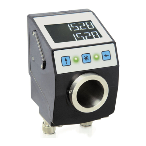
Fig. 1: Display and control elements
2.2 LCD display
The display range is limited to -199999 … 999999. Values outside this
range are displayed with "FULL".
The actual value is displayed in the first line and "----" in the second line. The target value
can be declared valid by means of CW.9 = 1 and displayed in the second line. If necessary, a
direction indicator (arrow) is also displayed.
The battery status is indicated by the battery symbol . If battery voltage Target value
acknowledgment mode critical value, the battery symbol on the display will flash. If the value
falls below a minimum value or if the battery is missing, the symbol lights permanently.
LED1
LED2
Display
LED3 (NS)
LED4 (L/A1)
LED6 (MS)
LED5 (L/A2)
Key Calibration
Key Incremental
measurement
Key Configuration

Display and control keys
AP20 Date: 16.05.2019 Art. No. 89948 Mod. status 134/19 Page 8 of 76
With incremental measurement function activated, the incremental measurement symbol
is shown.
This is signaled in red letters in the event of a fault.
Fig. 2: Two-line 14 segment LCD display
2.2.1 Extended display range
Values up to -199999 can be displayed by means of the control word. If the relevant bit has
been set and the value to be displayed is between -199999 and -999999, then the negative
sign and the digit of the highest order will flash alternately. If the value range drops below
-999999, "FULL" will be displayed.
2.3 LED display
2.3.1 Positioning status
A test sequence is executed on these LEDs during initialization.
When the target value is displayed, the LED1, LED2 inform about a deviation between the
actual value and the target window. The function of positioning status LEDs can be
configured.
2.3.1.1 Device status LED1, LED2
LED states valid at factory setting.
LED state
Description
off
No operating voltage or no valid target value.
green
Valid target value, actual value in the target window.
red
Valid target value, actual value outside target window.
In order for LED1 or LED2 to be controlled via the control word, this function of the LEDs must
be activated by means of parameters.
Incremetal
measurement
symbol
Display line 1
Battery symbol
Clockwise rotation
direction
Display line 2
Counterclockwise
rotation direction

Display and control keys
AP20 Date: 16.05.2019 Art. No. 89948 Mod. status 134/19 Page 9 of 76
2.3.2 Ethernet module status
A test sequence is executed on these LEDs during initialization.
LED3, LED4, LED5, and LED6 inform about the status of the Ethernet module. The functions of
the Ethernet module LEDs are permanently defined and cannot be changed.
2.3.2.1 Network status LED3
LED state
Description
off
No error or no operating voltage.
green
Online (RUN)
green, flashing
1x
Online (STOP)
green, flashing
3x
DCP_Identify
red
Fatal event
red, flashing 1x
Station name error (station name not set)
red, flashing 2x
IP address error (IP address not set)
red, flashing 3x
Configuration error (expected configuration differs from actual
configuration)
2.3.2.2 Link/Activity LED4, LED5
LED state
Description
off
No connection, no activity
green
Connection established, no activity
green, flickers
Connection established, activity
2.3.2.3 Module status LED6
LED state
Description
off
No error or no operating voltage
green
Normal operation
green, flashing
1x
Diagnosis event
red
Fatal event
2.4 Control keys
Pressing the Incremental button switches the increment function or a relative
measurement on or off.

Functional Description
AP20 Date: 16.05.2019 Art. No. 89948 Mod. status 134/19 Page 10 of 76
Pressing the Calibration button starts the calibration and acknowledges an existing fault.
In the "Alphanumeric display" operating mode, the receipt of a set point is acknowledged by
this action.
Pressing the Configuration button starts the parameterization.
See also Fig. 1.
3Functional Description
3.1 Operating modes
The following position-dependent operating modes are differentiated: Absolute position,
Differential value, Modulo and the position-independent operating mode Alpha-numeric
display.
3.1.1 Position-bound operating modes
The measured absolute position value is displayed, calculated depending on the Resolution,
Display Divisor, Decimal Places and Display Factor parameters. Via the interface, the actual
value can be provided to an upstream control and a target value specified.
Absolute position:
Linear absolute actual values are displayed
Line 1: actual value; CW.9 = 0, 2. Line: "----" or CW.9 = 1, Line 2: target value
Calculation of the actual value:
Actual value = Position value x calculation factor
Display divisor Position value = internally measured value + calibration value + offset value
Differential value display:
A linear absolute actual value and a differential value are displayed. The differential value is
calculated as follows: Differential value = actual value –target value.
Line 1: actual value; CW.9 = 0, 2. Line: "----" or CW.9 = 1, Line 2: Differential value
The calculation of the differential value can be set via the parameter Difference Value Mode
(see chapter 4.5.7).
Modulo display:
Actual values ranging from 0° to 360° are displayed.
Line 1: actual value; CW.9 = 0, 2. Line: "----" or CW.9 = 1, Line 2: target value
Using the parameter Decimal Places (see chapter 4.2.2) the resolution and the modulo point
of the displayed values are set.
Decimal places
Display resolution
Value range
0
1°
0°…360°
1
1/10°
0.0°…360.0°
2
1/100°
0.00°…360.00°

Functional Description
AP20 Date: 16.05.2019 Art. No. 89948 Mod. status 134/19 Page 11 of 76
Decimal places
Display resolution
Value range
3
1/1000°
0.000°…360.000°
4
1/10000°
0.0000°…360.0000°
Table 1: Modulo display
3.1.1.1 Target window
A target window is formed to be able to define a tolerance range.
Target window = Target Value ± Target Window
Example Position monitoring:
Target Window = 5
Target Value = 100
Fig. 3: Positioning monitoring with Target Window
An additional, extended target window and an associated visualization of the extended target
window can be additionally parameterized (see chapter 4.2.7 or 4.3.4).
Example of position monitoring with additionally activated Target Window Extended
parameter:
Target Window Extended = 15
Target Window Extended Visible = 1
Target Value = 100
Fig. 4: Positioning monitoring with Target Window Extended
100
+
-
Target
window
95
105
LED1
Positioning monitoring
LED2
+
-
Target
window
Extended Target
LED1
Positioning monitoring
85
115
LED2
100
95
105

Functional Description
AP20 Date: 16.05.2019 Art. No. 89948 Mod. status 134/19 Page 12 of 76
3.1.1.2 Directional arrows
To assist in positioning, direction arrows are displayed in the display as long as the current
actual value is outside the valid target window. The arrow direction indicates in which
direction the shaft must be moved to reach the target window.
3.1.1.3 LED display
With factory setting, the LED glows green as long as the actual value is within the
programmed window. When leaving target window, the LED glows red.The shaft must be
rotated in the direction of the glowing LED in order to arrive at the target value. The red
glowing LED1 (left): counter-clockwise (ccw) rotation required. Red glowing LED2 (right):
clockwise (cw) rotation required.
With factory settings, the LED display (see Fig. 1) has the following meaning:
Operating state
LED
Meaning
There is no valid target
value or no operating
voltage.
Both LEDs
inactive
No position monitoring active.
There is a valid target
value.
Both LEDs
green
The actual value is within the programmed target
window.
LED1 red
The actual value is outside the programmed target
window. The axis must be rotated counterclockwise to
reach the target window.
LED2 red
The actual value is outside the programmed target
window. The axis must be rotated clockwise to reach
the target window.
Table 2: LED display
3.1.1.4 Loop positioning
Target window is also applied to the loop length.
The behavior of the clearance compensation is independent of the set
counting direction of the display. The loop type must be changed to change
the clearance compensation.
If the position indicator is operated on a spindle or an additional gear, the spindle or external
gear backlash can be compensated by means of loop positioning. Therefore, movement
towards the target value is always in the same direction. This direction of approach can be
defined.
Example:
The direction, in which each setpoint position is to be moved to, is positive.
Case1 the new position is greater than actual value:
Die Sollposition wird direkt im Uhrzeigersinn (CW) angefahren.

Functional Description
AP20 Date: 16.05.2019 Art. No. 89948 Mod. status 134/19 Page 13 of 76
Case 2 the new position is smaller than actual value:
The directional arrows of the position indicator indicate that the loop length is to be
moved counterclockwise (CCW) beyond the target position. Them the target value is
approached clockwise.
Fig. 5: Positioning Loop CW
3.1.2 Control word: Position-dependent operating modes
The control word consists of 16 bits and differs in function depending on the operating mode.
Control word
15
14
13
12
11
10
9
8
7
6
5
4
3
2
1
0
MSB High Byte
Low Byte LSB
The designation of the individual bits of the control word as well as their meaning:
Bit
Meaning
Value = 0
Value = 1
0
Calibration execute
-
Trigger calibration (edge-
controlled, positive)
1
reserved
ever 0
-
2
reserved
ever 0
-
3
Display range
Normal display area
Extended display area
4
reserved
ever 0
-
5
Error acknowledge
-
Acknowledge error
6
reserved
ever 0
-
7
reserved
ever 0
-
8
reserved
ever 0
-
9
Target value activation
-
Activate target value
10
reserved
ever 0
-
11
LED1 green
Release via LED
parameters
required
Deactivate LED
Activate LED
12
LED1 red
Deactivate LED
Activate LED
13
LED2 green
Deactivate LED
Activate LED
14
LED2 red
Deactivate LED
Activate LED
Target value
CW
CCW
Clockwise positioning
Counterclockwise positioning
Positioning: loop CW
Loop length
Target window

Functional Description
AP20 Date: 16.05.2019 Art. No. 89948 Mod. status 134/19 Page 14 of 76
Bit
Meaning
Value = 0
Value = 1
15
LED blinking
Deactivate LED
Activate LED
Table 3: Control word Operating mode Abs, Diff, Modulo
3.1.3 Status word: Position-dependent operating modes
The response to a target write command contains a status word that has not
yet been updated.
The Status Word shows the current status of the AP20. It is composed of eight bits.
Status word
15
14
13
12
11
10
9
8
7
6
5
4
3
2
1
0
MSB High Byte
Low Byte LSB
The designation of the individual bits of the control word as well as their meaning:
Bit
Meaning
Value= 0
Value= 1
0
Direction indication CW
Counterclockwise target
value
Clockwise target value
1
Direction indication CCW
Clockwise target value
Counterclockwise target
value
2
Calibration executed
No calibration is currently
being carried out
A calibration is currently
being carried out
3
Target window extended
reached
Extended target window is
not reached
Extended target window is
reached
4
reserved
ever 0
-
5
Target window reached
Target window is not
reached
Target window is reached
6
Deviation
Deviation
Actual value <= target value
Deviation
Actual value > target value
7
General error
No error
There is an error
8
reserved
ever 0
-
9
Actual value =
incremental measurement
Increment measurement is
deactivated
Increment measurement is
activated
10
Target value activation
Target value is not activated
Target value is activated
11
Battery state
Battery
Charging state is OK
Battery
Charging state is critical
12
Sensor error
There is no sensor error
There is a sensor error
13
Key Configuration
Button is not pressed
Button is pressed
14
Key Calibration
Button is not pressed
Button is pressed
15
Key Incremental
Button is not pressed
Button is pressed
Table 4: Status word Operating mode Abs, Diff, Modulo

Functional Description
AP20 Date: 16.05.2019 Art. No. 89948 Mod. status 134/19 Page 15 of 76
3.1.4 Alpha-numeric display operating mode
Two 6-digit target values can be displayed in this operating mode. With factory settings, the
target values are acknowledged by pressing the key (see chapter 2.4 and
parameter 4.5.15).
Alpha-numeric display:
Both lines are freely writable. The content of the display line can be transmitted via the
Display Data parameter, and the content of the display line can be transmitted via the Target
Value parameter. In this case, the bit for data identification must be set correctly in the
respective control word. The data identifier is used to distinguish whether the data is
interpreted and displayed as a number or as an alphanumeric character (ASCII)
(see chapter 4.2.10, 4.2.12 and 4.5.2).
Alternatively, you can write directly in each display line using the Display String parameter in
connection with the respective Display String1 or Display String2 (see chapter 4.5.2, 4.5.4
and 4.5.5)
LCD display:
If there is no valid target value, the 1st display line is displayed blank. "----" appears in the
2nd display line.
A valid target value is displayed flashing until its receipt is acknowledged. If neither target
value has been acknowledged, both values are acknowledged jointly by pressing the key.
LED display:
Status LED1 and LED2:
With factory settings, the LED display (LED1, LED2) works according to the following table.
Operating state
State
Meaning
There is no valid target
value.
Both LEDs off
There is a valid target
value.
LED1 red
Display data not acknowledged
LED1 green
Display data acknowledged
LED2 red
Target value not acknowledged
LED2 green
Target value acknowledged
Table 5: Status LED display in the alpha-numeric display operating mode
3.1.5 Control word: Alpha-numeric display operating mode
In the control word, the relevant type (number or character string) and the validity of the
target value is transmitted to the display. As an additional option, the target value can be
acknowledged via the control word.
The control word is composed of 16 bits.

Functional Description
AP20 Date: 16.05.2019 Art. No. 89948 Mod. status 134/19 Page 16 of 76
Control word
15
14
13
12
11
10
9
8
7
6
5
4
3
2
1
0
MSB High Byte
Low Byte LSB
The designation of the individual bits of the control word as well as their meaning:
Bit
Meaning
Value = 0
Value = 1
0
reserved
ever 0
-
1
reserved
ever 0
-
2
Display data activation (display
line 1)
-
Activate Display data
3
Display range
standard
extended
4
reserved
ever 0
-
5
Error acknowledge
-
Acknowledge error
6
Target value acknowledgment
mode (display line 2)
Manually acknowledge
target value
Acknowledge target value
7
Target value data type (display
line 2)
Interpret target value
as a number
Interpret target value as
ASCII character
8
Display data data type (display
line 1)
Interpret display data
as a number
Interpret display data as
ASCII character
9
Target value activation (display
line 2)
-
Activate target value
10
Display data acknowledgment
mode
Manually acknowledge
display data
Acknowledge display data
11
LED1 green
Function
controlled via
parameters
LED1, LED2
Deactivate LED
Activate LED
12
LED1 red
Deactivate LED
Activate LED
13
LED2 green
Deactivate LED
Activate LED
14
LED2 red
Deactivate LED
Activate LED
15
LED blinking
Deactivate LED
Activate LED
Table 6: Control word alpha-numeric display operating mode
3.1.6 Status word: Alpha-numeric display operating mode
The response to a target write command contains a status word that has not
yet been updated.
Type, validity and acknowledgment status of the target values are fed back in the status word.
The status word is composed of 16 bits.
Status word
15
14
13
12
11
10
9
8
7
6
5
4
3
2
1
0
MSB High Byte
Low Byte LSB
The designation of the individual bits of the control word as well as their meaning:
Bit
Meaning
Value = 0
Value = 1
0
reserved
ever 0
-

Functional Description
AP20 Date: 16.05.2019 Art. No. 89948 Mod. status 134/19 Page 17 of 76
Bit
Meaning
Value = 0
Value = 1
1
reserved
ever 0
-
2
Display data activation
(display line 1)
Display data deactivated
Activate display data
3
Target value
acknowledged (display
line 2)
Target value not
acknowledged
Target value acknowledged
4
reserved
ever 0
-
5
Display data
acknowledged (display
line 1)
Display data not
acknowledged
Display data acknowledged
6
reserved
ever 0
-
7
General error
No error
An error exists
8
Display data format
(display line 1)
Display data are interpreted
as a number
Display data are interpreted
as an ASCII character
9
Target value format
(display line 2)
Target value is interpreted
as a number
Target value is interpreted
as an ASCII character
10
Target value activation
(display line 2)
Target value is deactivated
Target value is activated
11
Battery state
Battery
Charging state is OK
Battery
Charging state is critical
12
Sensor error
There is no sensor error
There is a sensor error
13
Key Configuration
Button is not pressed
Button is pressed
14
Key Calibration
Button is not pressed
Button is pressed
15
Key Incremental
Button is not pressed
Button is pressed
Table 7: Status word alpha-numeric display operating mode
3.2 Battery buffering
Without an external power supply, encoder changes are recorded with battery support.
Depending on the duration of battery operation (including storage) and the frequency of
adjustments without an external power supply, the battery life is approximately 8 years.
Battery voltage is checked at intervals of approx. 10 min. If battery voltage drops below a
specified value, the battery symbol will blink on the display. If the battery voltage
continues to drop, will be displayed permanently. The battery should be replaced within
approx. three months after the first appearance of the battery symbol. For battery
replacement it is mandatory to follow the instructions of the installation instructions.
Replacement can also take place at the SIKO distribution partners or in the SIKO main plant.
Behavior of the status word
The charge status of the battery is signified in the status word. In the case of a critical
charging voltage, bit 11 is set, and in the case of an empty or non-existing battery, a fault is
additionally signaled with bit 7.

Functional Description
AP20 Date: 16.05.2019 Art. No. 89948 Mod. status 134/19 Page 18 of 76
3.3 Parameterization of the position indicator
The position indicator can be fully parameterized via the bus interface. All parameters can
also be set manually with the help of the keyboard.
3.3.1 Manual parameterization
3.3.1.1 Starting parameterization
The time until menu release is displayed when the button is pressed. Parameterization
starts if it is actuated for the duration of the enable time (see chapter 2.4 and 4.5.14).
3.3.1.2 Value input
Enter values via the key and the key. Confirm values entered by pressing the key.
- decimal place selection key
- value input key
3.3.1.3 Value selection
For some parameters you can select values from a list.
Direct value input is not possible there.
Pressing the key, the value can be selected from the list. By pressing the key, the
selection is confirmed.

Functional Description
AP20 Date: 16.05.2019 Art. No. 89948 Mod. status 134/19 Page 19 of 76
3.3.1.4 Overview of the operating menu
PIN entry
required
Start
Key enable time expired?
Changeable parameter
chPARA
Read-only device data
RdOnLY
Diagnosis
DIAGN
Menu changeable
parameters
Menu readable
parameters
Menu error
memory
presentation
End
yes
PIN correct? yes
no
Quit
>QUIT<
no
Hold down
the key
On the display:
Time delay of the
menu release
CONFIG
5
Fig. 6: Operating menu
All device parameters can be viewed and changed in the "Changeable parameters" ("chPARA")
submenu (see chapter 3.3.1.5).
All fixed device data are displayed in the "Readable parameters" (Read Only = "RdOnLY")
submenu (see chapter 3.5.1).
The "Diagnosis" ("DIAGN") submenu provides various diagnostic options (see chapter 3.5.2).

Functional Description
AP20 Date: 16.05.2019 Art. No. 89948 Mod. status 134/19 Page 20 of 76
3.3.1.5 "Changeable parameters" menu
When choosing the "Changeable parameters" submenu, a PIN must be entered first. In the
standard delivery condition, this is: "00000".
After confirming the correct PIN, you can choose among the following parameter menus.
Description
Display
Chapter
Quick Setup
QUICK
SETUP
3.3.1.6
PROFINET
SETEPN
3.3.1.7
Positioning
POSI
3.3.1.8
Visualization
VISUAL
3.3.1.9
LED function
LEDS
3.3.1.10
Device options
OPTION
3.3.1.11
Menu end
<QUIT>
Table 8: "Changeable parameters" menu structure
3.3.1.6 Quick Setup
The following parameters can be set in the QUICK SETUP menu:
Description
Display
Chapter
Display direction
DISPL
4.3.1
Network configuration address
SET ID
Fig. 7
Network configuration
SET NW
Fig. 7
When "DEVICE" is selected
Network IP Configuration
SET IP
5.1.1
- IP-Address 1,2 Byte
IP 12
- IP-Address 3,4 Byte
IP 34
- Subnet mask 1,2 Byte
SNM 12
- Subnet mask 1,2 Byte
SNM 34
- Gateway 1,2 Byte
GATW12
- Gateway 3,4 Byte
GATW34
Resolution
RESOL
4.2.1
Decimal places
DEC PL
4.2.2
Counting direction
CntDIR
4.2.3
Target window
TW
4.2.6
Restart
RESET
YES
No
Menu end
<QUIT>
Table 9: "QUICK SETUP" menu
Other manuals for AP20
1
Table of contents
Other Siko Measuring Instrument manuals
Popular Measuring Instrument manuals by other brands
ATAGO
ATAGO PALETTE Series instruction manual
Electro Industries/GaugeTech
Electro Industries/GaugeTech Shark 100T quick start guide
Extech Instruments
Extech Instruments GRT350 user manual
Instrutech
Instrutech Busy Bee PCM301 user manual
Datum
Datum 4040B operating manual
TESTO
TESTO Saveris Series Commissioning instructions


