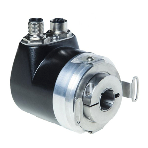
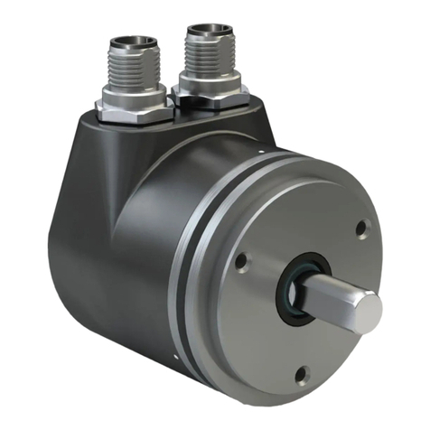
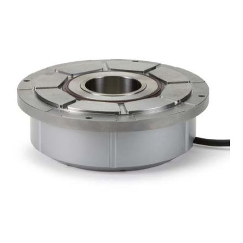
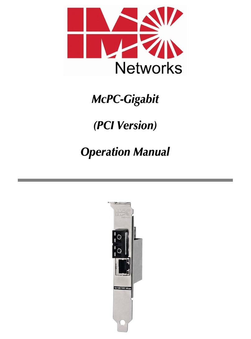
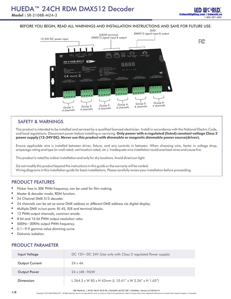
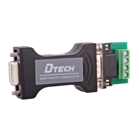
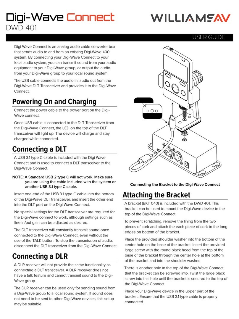
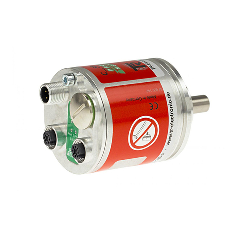
Siko WK50/1 Operation manual

WK50/1 Datum 22.04.2009 Art.Nr. 77787 Änd. Stand 111/09 1
Abb. 1: Montagehinweise
DEUTSCH
1. Gewährleistungshinweise
Lesen Sie vor der Montage und der Inbetriebnahme
dieses Dokument sorgfältig durch. Beachten Sie zu
Ihrer eigenen Sicherheit und der Betriebssicherheit
alle Warnungen und Hinweise.
Ihr Produkt hat unser Werk in geprüftem und be-
triebsbereitem Zustand verlassen. Für den Betrieb
gelten die angegeben Spezifikationen und die
Angaben auf dem Typenschild als Bedingung.
Garantieansprüche gelten nur für Produkte der
Firma SIKO GmbH. Bei dem Einsatz in Verbindung
mit Fremdprodukten besteht für das Gesamtsystem
kein Garantieanspruch.
Bei Störungen oder Geräteausfällen sollten Sie
niemals versuchen, die Geräte selbst zu öffnen.
Ansonsten setzen Sie sich der Gefahr aus, mit
Teilen, die unter hoher Spannung stehen, in
Kontakt zu geraten.
Reparaturen dürfen nur im Werk vorgenommen
werden. Für weitere Fragen steht Ihnen die Firma
SIKO GmbH gerne zur Verfügung.
2. Identifikation
Das Typenschild zeigt den Gerätetyp mit Varianten-
nummer. Die Lieferpapiere ordnen jeder Varianten-
nummer eine detaillierte Bestellbezeichnung zu.
z.B. WK50/1-0023
Varianten-Nr.
Geräte-Typ
•
•
•
•
•
3. Mechanische Montage
Die Montage darf nur gemäß der angegebenen IP-
Schutzart vorgenommen werden. Das System muss
ggfs. zusätzlich gegen schädliche Umwelteinflüs-
se, wie z.B. Spritzwasser, Staub, Schläge, Tempe-
ratur geschützt werden.
Achtung! Radialdichtringe sind Verschleißteile!
Die Schutzart ist deshalb abhängig von Lebens-
dauer und Zustand der Dichtringe.
3.1 Montagehinweise
Gehen Sie sorgfältig mit dem Geber um. Es handelt
sich um ein Präzisionsmessgerät. Folgende Punkte
führen unverzüglich zum Verfall der Garantie:
Zerlegen oder Öffnen des Gebers (soweit dies nicht in
dieser Benutzerinformation beschrieben wird).
Schläge auf den Geber oder die Welle, da dadurch
interne Elemente wie z.B. die optische Kodescheibe
beschädigt werden können.
Mechanische Bearbeitung der Welle, des Flansches
oder Gehäuses (Bohren, Fräsen, usw.). Hierdurch
kann es zu schweren Beschädigungen der inneren
Teile des Gebers kommen.
Unzulässige axiale oder radiale Belastung der Welle.
Unsachgemäße Befestigung des Gebers.
•
•
•
•
•
Benutzerinformation
WK50/1
Winkelkodierer Multiturn
4. Elektrischer Anschluss
Anschlussverbindungen dürfen nicht unter
Spannung geschlossen oder gelöst werden!
Verdrahtungsarbeiten dürfen nur spannungslos
erfolgen.
Vor dem Einschalten sind alle Leitungsanschlüsse
und Steckverbindungen zu überprüfen.
Für Geber mit Parallelausgang: nicht benutzteSi-
gnalleitungen sind über einen Widerstand (z.B. R
= 10 k) gegen Masse zu schalten.
Die Betriebsspannung muss gemeinsam mit der
Folgeelektronik (z.B. Steuerung) eingeschaltet
werden.
•
•
•
•
•

2 WK50/1 Datum 22.04.2009 Art.Nr. 77787 Änd. Stand 111/09
Litzen sind mit Aderendhülsen zu versehen.
Die Schnittstellensignale DÜA und DÜB sind bei
Nichtgebrauch an GND anzuschließen.
Hinweise zur Störsicherheit
Alle Anschlüsse sind gegen äußere Störeinflüsse
geschützt. Der Einsatzort ist aber so zu wählen,
dass induktive oder kapazitive Störungen nicht
auf den Geber oder dessen Anschlussleitungen
einwirken können! Durch geeignete Kabelfüh-
rung und Verdrahtung können Störeinflüsse (z.B.
von Schaltnetzteilen, Motoren, getakteten Reg-
lern oder Schützen) vermindert werden.
Erforderliche Maßnahmen
Nur geschirmtes Kabel verwenden. Den Kabelschirm
beidseitig auflegen. Litzenquerschnitt der Leitun-
gen min. 0,14mm2, max. 0,5mm2.
Die Verdrahtung von Abschirmung und Masse (0V)
muss sternförmig und großflächig erfolgen.
Das System muss in möglichst großem Abstand von
Leitungen eingebaut werden, die mit Störungen
belastet sind; ggfs. sind zusätzliche Maßnahmen
wie Schirmbleche oder metallisierte Gehäuse
vorzusehen. Leitungsführungen parallel zu Ener-
gieleitungen vermeiden.
Schützspulen müssen mit Funkenlöschgliedern
beschaltet sein.
Spannungsversorgung
Die Spannungswerte sind abhängig von der Ge-
räteausführung und sind den Lieferpapieren oder
dem Typenschild zu entnehmen.
z.B.: 24VDC±20%
4.1 Schnittstellen
Parallele Schnittstelle P1 (push-Pull)
Aus technischen Gründen stehen nur 20 Ausgänge
zur Verfügung, die auf die maximal möglichen 13
(Single-Turn) + 12 Bit (Multi-Turn) abgebildet wer-
den können. Standardmäßig ist der Geber so einge-
stellt, dass er mit eingegrenztem Multi-Turn-Bereich
arbeitet, also 13 + 7 Bit. Dies entspricht einer Auflö-
sung von 1 048 576 Schritten. Über die vorhandene
Programmierschnittstelle (siehe Kap. 6) kann dieser
Bereich jedoch auf Kosten der Auflösung verschoben
werden. Weitere Informationen zum Funktionsprinzip
der parallelen Schnittstelle sind dem SIKO-Prospekt
"Winkelcodierer" zu entnehmen.
Serielle Schnittstellen
Bei den Ausgangsbeschaltungen S3/01 (RS485
mit SIKONETZ-Protokoll), S6/04 (RS422/Synchron
Serielles Interface SSI), IB3 (Sensor-/Aktor-Feld-
bussystem InterBus-S mit ENCOM Profil K3) sowie
•
•
•
•
•
•
PB (Profibus-DP-Profil für Encoder Class 1) mit
entsprechender Folgeelektronik (Direktanschluss
an Messanzeige oder Terminal) ist die volle Geber-
auflösung verfügbar (13+12=25Bit).
Bei SSI bzw. Feldbussystem SIKONETZ kann die
Auflösung des Gebers über die Programmier-
schnittstelle (siehe Kapitel 6) entsprechend um-
konfiguriert werden.
Bei InterBus-S oder Profibus-DP muss die Konfigu-
ration der Geberauflösung bei SIKO erfolgen oder
die Nachfolgeelektronik entsprechend program-
miert werden.
Serielle Schnittstelle S6/04 (SSI)
Weitere Informationen zum Funktionsprinzip der
SSI-Schnittstelle sind dem SIKO-Prospekt "Win-
kelcodierer" zu entnehmen.
Serielle Schnittstelle S3/01 (SIKONETZ)
Die SIKONETZ-Schnittstelle erlaubt den Betrieb
des Winkelcodierers in einem Bus-System. Die
Beschreibung der Hardware- und Software-Funk-
tionen sind umfangreich und nicht in dieser Be-
nutzerinformation enthalten. Bitte ziehen Sie für
alle die SIKONETZ-Schnittstelle betreffenden Fra-
gen die SIKONETZ-Dokumentation heran, in der
ausführliche Informationen über Anwendung und
Programmierung enthalten sind.
Serielle Schnittstelle IB3 (Interbus-S)
Der Feldbus INTERBUS-S ist als Installationsfern-
bus aufgebaut, d.h. über das Buskabel wird der
Geber mit Spannung versorgt. Die InterBus-S-
Schnittstelle wird ausführlich in den Unterlagen
der Fa. PHOENIX, Blomberg beschrieben.
Hinweis Busabschluss: Eine Brücke im Stecker
der weiterführenden Busleitung von Pin 9 (/RBST)
nach Pin 5 (GND) zeigt dem auf der Interbus-Karte
vorhandenen Protokoll-Chip an, dass die Busleitung
auf einen weiteren Interbus-S-Teilnehmer führt.
Hinweis Identifikation:
- Identnummer: 37Hex (= 55DEZ)
- Datenwortbreite: 2 Worte (= 4 Bytes)
Serielle Schnittstelle PB (Profibus-DP)
Hinweis Busabschluss: Bei Busbetrieb muss beim
letzten Gerät am Bus (am Ende der Busleitung)
ein Busabschluss eingefügt werden. Dieser Busab-
schluss, in Form eines Steckers, kann als Zubehör
über die Firma SIKO unter der Bezeichnung BAS-
0002 bezogen werden.
5. Anschlussarten
Achtung! Die Signale 0V und GND sind nicht
identisch und dürfen nicht miteinander verbun-
den werden!

WK50/1 Datum 22.04.2009 Art.Nr. 77787 Änd. Stand 111/09 3
Ansichtseite = Steckseite
Stiftkontakt Geräteseite
Ansichtseite = Lötseite
Buchsenkontakt Gegenstecker
Ansichtseite = Steckseite
Buchsenkontakt Geräteseite
Ansichtseite = Lötseite
Stiftkontakt Gegenstecker
Ansichtseite = Steckseite
Stiftkontakt Geräteseite
Ansichtseite = Lötseite
Buchsenkontakt Gegenstecker
Ansichtseite = Steckseite
Stiftkontakt Geräteseite
Ansichtseite = Lötseite
Buchsenkontakt
Gegenstecker
Ansichtseite = Steckseite
Buchsenkontakt Geräteseite
Ansichtseite = Lötseite
Stiftkontakt Gegenstecker
Ansichtseite = Steckseite
Stiftkontakt Geräteseite
Ansichtseite = Lötseite
Buchsenkontakt
Gegenstecker
Ansichtseite = Steckseite
Buchsenkontakt Geräteseite
5.1 Anschlussart E1
Parallele Schnittstelle P1 (Push-Pull)
Kabelfarbe Signal Kabelfarbe Signal
rot D0 weißrosa D13
blau D1 rosabraun D14
gelb D2 rotblau D15
grün D3 weißgrün D16
weiß D4 graurosa D17
rosa D5 braunrot D18
schwarz D6 braunblau D19
violett D7 weißrot DÜA (Schnittstelle)
braungrün D8 weißblau DÜB (Schnittstelle)
weißgelb D9 weißschwarz GND (Schnittstelle)
gelbbraun D10 braun +UB (Versorgung)
grauweiß D11 grau OV (Versorgung)
graubraun D12
5.2 Anschlussart E2
Serielle Schnittstelle S6/04 (SSI) 9-pol.
PIN Kabelfarbe Signal
1 rosa Daten-
2 blau Daten+
3 rot Takt-
4 schwarz Takt+
5 braun +UB (Versorgung)
6 weiß GND (Schnittstelle)
7 gelb DÜA (Schnittstelle)
8 grün DÜB (Schnittstelle)
9 grau 0V (Versorgung)
5.3 Anschlussart E4
Serielle Schnittstelle S3/01 (SIKONETZ) 7-pol.
PIN Kabelfarbe Signal PIN Kabelfarbe Signal
1 rot D0 14 weißrosa D13
2 blau D1 15 rosabraun D14
3 gelb D2 16 rotblau D15
4 grün D3 17 weißgrün D16
5 weiß D4 18 graurosa D17
6 rosa D5 19 braunrot D18
7 schwarz D6 20 braunblau D19
8 violett D7 21 weißrot DÜA
(Schnittstelle)
9 braungrün D8 22 weißblau DÜB
(Schnittstelle)
10 weißgelb D9 23 weißschwarz GND
(Schnittstelle)
11 gelbbraun D10 24 braun +UB
(Versorgung)
12 grauweiß D11 25 grau OV
(Versorgung)
13 graubraun D12 26 - - - - - -
5.5 Anschlussart E7
Serielle Schnittstelle IB3 (Interbus-S) 9-pol.
ankommender Fernbus (Stift)
PIN Kabelfarbe Signal
1 gelb D0
2 grün D0
3 grau DI
4 rosa DI
5 braun GND (Schnittstelle)
6 grüngelb PE
7 rot +UB (Versorgung)
8 blau 0V (Versorgung)
9 - - - - - -
weiterführender Fernbus (Buchse)
PIN Kabelfarbe Signal
1 gelb D0
2 grün D0
3 grau DI
4 rosa DI
5 braun GND (Schnittstelle)
6 grüngelb PE
7 rot +UB (Versorgung)
8 blau 0V (Versorgung)
9 - - - RBST
Serielle Schnittstelle PB (Profibus-DP)
PIN Signal
1 DGND (2M)
2 RXD/TXD-N (A-Line)
3 - - -
4 RXD/TXD-P (B-Line)
5 - - -
6 VP (2P5)
7 +EV (+24V)
8 0V
9-11 - - -
12 RTS
PIN Kabelfarbe Signal
1 weiß GND (Schnittstelle)
2 - - - - - -
3 blau DÜB (Schnittstelle)
4 grün DÜA (Schnittstelle)
5 braun +UB (Versorgung)
6 grau 0V (Versorgung)
7 - - - - - -
5.4 Anschlussart E6
Parallele Schnittstelle P1 (Push-Pull) 26-pol.

4 WK50/1 Datum 22.04.2009 Art.Nr. 77787 Änd. Stand 111/09
Stiftteil
Buchsenteil
Schirm
Schirm
Anschlussart E4
Anschluss mit Kupplungsstecker und Kupplungsdo-
se der Fa. Binder Serie 423.
Adapter (Pos. 1) und Dichtelement (Pos. 2) auf
das Kabel schieben.
Kabel-Außenmantel auf 22mm abisolieren.
Schirmgeflecht 90° hochstellen. Schirmhülse
(Pos. 3) über die Folie bzw. Baumwollgeflecht,
jedoch unter das Schirmgefecht schieben;
1.
2.
3.
Schirmgeflecht bündig mit Außendurchmesser
Schirmhülse (Pos. 3) schneiden.
Folie, Füller und innere Isolierung abschneiden,
Litzen auf 3,5mm abisolieren, verdrillen und
verzinnen.
Litzen an Kontakteinsatz (Pos. 4) anlöten. Rändel
(Pos. 7) über Einsatzhülse (Pos. 6) schieben. Dis-
tanzhülse (Pos. 5) zwischen Einsatz (Pos. 4) und
Schirmhülse (Pos. 3) einfügen und schließen.
Einsatz (Pos. 4), Distanzhülse (Pos. 5) und
Schirmhülse (Pos. 3) in Einsatzhülse (Pos. 6)
einführen. Hierbei ist zu beachten, dass die
gewünschte Codiernut des Einsatzes (Pos. 4) in
den Codiersteg eingeführt wird.
Einsatzhülse (Pos. 6) mit Hilfe des Montageschlüs-
sels (Pos. 8 oder Gegenstecker am Geber), mit
Adapter (Pos. 1) auf Anschlag verschrauben.
Wichtig: Axialspiel zwischen Rändelmutter (Pos.
7) und Adapter (Pos. 1) max. 0,2mm.
6. Programmierung
Der Geber läßt sich bei den Ausführungen P1 (Par-
allel / Push-Pull), S6/04 (SSI) und S3/01 (SIKO-
NETZ) so programmieren, dass seine Parameter auf
die Anforderungen der Anwendung oder Nachfol-
geelektronik angepasst werden können. Dadurch
kann z.B. eingestellt werden, ob die Ausgabe des
Codewertes in Gray- oder Binärwerten erfolgen
soll. Für die Programmierung steht ein spezieller
Befehlssatz zur Verfügung.
Bei InterBus-S oder Profibus-DP muss die Konfigu-
ration des Gebers bei SIKO erfolgen oder die Nachfol-
geelektronik entsprechend programmiert werden.
Programmierschnittstelle RS485
Die Anschlüsse der Programmierschnittstelle (DÜA,
DÜB und GND) sind am Stecker oder als Kabelen-
den verfügbar (siehe Kapitel 4.1).
Achtung! Zur Programmierung von Gebern mit
SIKONETZ-Datenschnittstelle muss die Busadresse
durch Betätigung des Kodierschalters auf 0 ge-
setzt werden (s. Kapitel 9).
Zur Anpassung der RS485-Pegel an eine RS232-
Schnittstelle (z.B. eines PCs) kann ein Pegelwand-
ler (z.B. Fa.Spectra Typ I-7520) verwendet werden.
Dieser benötigt eine externe Spannungsversorgung,
die während der Programmierung auch den Geber
versorgen kann, so dass die Geber z.B. bequem vor
dem Anbau programmiert werden können.
Befehle gehen in Richtung Geber, Antworten kom-
men vom Geber. Das Programmiergerät ist der 'ak-
tive' Teil.
4.
5.
6.
7.
Pos. 6 ... 10 über Kabelmantel schieben.
Kabel abisolieren.
Schirm umlegen.
Pos. 5 auf Litzen schieben.
Kabel an Pos. 3 löten (entspr. Anschlussplan).
Abstandshülse Pos. 4 aufweiten und über Lit-
zen stülpen, zusammendrücken und auf Pos. 3
stecken. Schlitz und Nut (Pos. 3 und 4) müssen
deckungsgleich sein.
Pos. 6 an Pos. 5 drücken, überstehenden Schirm
abschneiden.
Pos. 2 und 7 aufschieben und mittels Montage-
werkzeug Pos. 11 verschrauben.
Pos. 8 in Pos. 9 stecken, beides in Pos. 7
schieben.
Pos. 10 mit Pos. 7 verschrauben.
Pos. 1 in Pos. 2 schieben.
Anschlussart E2 und E7
1.
2.
3.
4.
5.
6.
7.
8.
9.
10.
11.

WK50/1 Datum 22.04.2009 Art.Nr. 77787 Änd. Stand 111/09 5
7. Beschreibung (Interbus-S) des
Prozessdatenworts
Der WK50/1-IB3 stellt einen Interbus-Teilnehmer
mit einer Datenbreite von 32 Bit dar. Die Bedeu-
tung dieser 32 Bit sind nachfolgend beschrieben:
Statusbits
Bit 31
Bit 28
Bit 25
24
Bit 0
Bit
0 0 0 0 0 Positionswert
Positionswert gültig
In den Bits B0 bis B24 ist der Positionsistwert des
angeschlossenen Gebers enthalten. Dieser liegt als
Zweierkomplement-Wert in binärer Form vor und ist
rechtsbündig angeordnet. Das Bit 24 ist also als
Vorzeichen zu interpretieren. Der darstellbare Wer-
tebereich ist somit auf -224...+224 - 1 festgelegt.
Die Bits 25 ... 28 und 30 ... 31 stellen Steuer- und Sta-
tusbits dar. Sind diese Bits auf 0 gesetzt, so entspricht
dies dem Zustand BETRIEB und auf den Bits B0 bis
B24 wird ein gültiger Positionsistwert ausgegeben.
Ab Firmware-Version 3.00 wird die Beleuchtungs-
LED der optischen Abtastung überwacht. Fällt die
LED aus bzw. sinkt die Lichtleistung unter einen
bestimmten Schwellwert, so wird ein Störungssi-
gnal generiert. Dieses Störungssignal wird in den
Statusbits des Prozessdatenworts untergebracht
und muss von dem angeschlossenen Interbus-Mas-
ter ausgewertet werden!
Ein ungültiger Positionsistwert wird durch ein ge-
setztes Bit an der Stelle Bit 31 gekennzeichnet.
Zusätzlich zeigt eine Bitkombination an den Stel-
len B25 ... B28 die Störungsursache an. Im unten
abgebildeten Beispiel wird als Störungscode der
Wert 1101 angezeigt, dies entspricht dem Fehler:
"LED-Ausfall".
Statusbits
Bit 31
Bit 28
Bit 25
24
Bit 0
Bit
1 0 1 1 0 1 ungültiger Positionswert
Positionswert ungültig
Diese Fehlermeldung bleibt mindestens so lan-
ge bestehen, bis von dem Interbus-Master diese
Meldung quittiert wird, indm er an den Geber ein
Steuerwort mit gesetztem Bit 31 sendet ( die rest-
lichen Bits sind auf 0 gesetzt):
Statusbits
Bit 31
Bit 28
Bit 25
24
Bit 0
Bit
1 0 0 0 0 0 0 0
Quittierungswort vom Master an den WK50/1-IB3
Sollte der Fehler nicht mehr auftreten, dann löscht
der WK50/1 nach Empfang der Quittierung die
Statusbits in seinem Prozessdatenwort und liefert
wieder den korrekten Positionswert. Im Falle eines
dauerhaften Fehlerzustandes bleiben die entspre-
chenden Statusbits gesetzt.
8. Geräteprofil (Profibus-DP)
WK50/1-PB besitzt eine Funktionalität, die auf
dem PROFIBUS-Profil für Encoder Class 1 (Version
1.1, Mai 1997) basiert. Somit sind folgende Eigen-
schaften definiert:
Positionswert, dargestellt im 32-Bit-Format, binär
codiert, rechtsbündig angeordnet.
Octet 1 2 3 4
Bit 31-24 23-16 15-8 7-0
Data 231 - 224 223 - 216 215 - 2827 - 20
Data-Exchange - 16 Bit
Preset-Funktion (setzt den aktuellen Positionswert
auf den Preset-Wert, Wertebereich = 15 Bit d. h.
0 ... 32767).
Octet 1 2 3 4
Bit 31 30 - 24 23-16 15-8 7-0
Data 0/1 230 - 224 223 - 216 215 - 2827 - 20
Preset
Control Preset Value - max. 31 Bit
-16 Byte Diagnoseinformation
Diagnostic
Funktion
Datentyp Diagnostic
Octet num.
Wert
Stationsstatus 1 Byte 1 DP-Slave-abhängige In-
formationen. Definiert
in EN 50 170
Stationsstatus 2 Byte 2
Stationsstatus 3 Byte 3
Diag.Master_Add Byte 4 Adresse des DP-Master
Ident-Nummer Word 5, 6 Identnr. des Slave
Extended diag-
nostic header
Byte 7 Anzahl der erweiterten
Diagnosebytes
Alarms Byte 8 Bei WK50/1-PB immer 0
Operating status Byte 9 0 = steigende Positions-
werte bei Drehrichtung
im Uhrzeigersinn,
1 = steigende Positions-
werte bei Drehrichtung
entgegen dem Uhrzei-
gersinn.
Encoder-Typ Byte 10 1 = Multi-Turn
Singleturn-
Auflösung
Long
(4 Byte)
11 - 14 8192 ( 13 Bit)
Anzahl unter-
scheidbarer Um-
drehungen
Int
(2 Byte)
15, 16 4096 ( 12 Bit)
Eine detaillierte Beschreibung der verschiedenen
Parameter ist dem PROFIBUS-DP-Profil für Encoder
zu entnehmen.
•
•
•

6 WK50/1 Datum 22.04.2009 Art.Nr. 77787 Änd. Stand 111/09
8.1 Gerätestammdatei und Projektierung
Für WK50/1-PB wurde eine Gerätestammdatenda-
tei (GSD)mit dem Namen SIKOOOEF.GSD erstellt.
Diese Datei kann mit dem verwendeten Projektie-
rungstool, z.B. COM PROFIBUS der Firma Siemens,
in die Gerätebibliothek aufgenommen werden (die
Vorgehensweise hierfür entnehmen Sie bitte den
Unterlagen für das Projektierungstool).
8.2 Konfiguration
Die Konfiguration des WK50/1-PB erfolgt in der
Projektierungsphase über die GSD, die auf Anfor-
derung erhältlich ist oder unter http://www.siko.
de/download.
Bei der Auswahl des Slaves WK50/1-Profibus aus
der Bibliothek werden 4 konsistente Eingabebytes zur
Übergabe des Preset-Wertes und 4 konsistente Ausga-
bebytes zur Übergabe des Positionswertes reserviert.
8.3 Parametrierung
In der Parametrierungspgase beim Systemanlauf
werden an den WK50/1-PB 2 User-Parameterbytes
übergeben (Octet 8 und 9). Die Octets 1..7 wer-
den aus der GSD geliefert und sind vom Benutzer
nicht veränderbar. Der Inhalt von Octet 8 wird vom
Projektierungstool anhand der Angaben in der GSD-
Datei bestimmt. Über das Bit 0 im Octet 9 kann die
Zählrichtung umgeschaltet werden. Dabei bedeutet:
0: steigende Positionswerte bei Drehrichtung im
Uhrzeigersinn.
1: steigende Positionswerte bei Drehrichtung ent-
gegen dem Uhrzeigersinn.
8.4 Telegrammaufbau im Zustand DATA-EXCHANGE
Während des Betriebs werden 4 Bytes Eingabeda-
ten und 4 Bytes Ausgabedaten zyklisch zwischen
einem Master und dem WK50/1-PB ausgetauscht.
8.4.1 Eingabeparameter Preset Wert
4 konsistente Datenbytes, Format 31-Bit Integer,
MS-Bit (Bit 30) wird als Übergabebit für den Pre-
set-Wert in Bit 30..0 verwendet (in Bit 30 steht
das MS-Bit des Preset-Wertes).
Bit 31 = 0: Normaler Betrieb, keine Änderung des
Preset-Wertes.
Bit 31 = 1: Preset-Mode, der in Bit 30..0 stehende
Wert wird als neuer Preset-Wert übernommen.
Der Positionswert wird anschließend auf den über-
nommenen Preset-Wert gesetzt.
Mit Hilfe des Preset-Wertes wird eine Nullpunkt-
verschiebung erreicht. Beispiel: Preset-Wert auf
10000 gesetzt -> Nach Betätigen der Nullpunkt-
taste wird der Positionswert auf 10000 gesetzt.
Der voreingestellte Wert ist 0.
8.4.2 Ausgabeparameter Positions-Wert
4 konstante Datenbytes, Format 32-Bit Integer,
MS-Bit (Bit 31).
9. Befehlsliste Servicebetrieb
(Parallel, SSI, SIKONETZ, Interbus-S)
Parameter: 4800 Baud, kein Parity, 8Bit,
1 Stopbit, ohne Handshake
Ausgabe: ASCII
Wertebereiche: 2/3 Byte: 0...65535 / 0...± 223
Befehl Länge
(incl.
Return)
Antwort Beschreibung
ax 2/7 xxxxxx Gerätetyp/ Softwareversion
x=0: Gerät
x=1: Softwareversion
x=2: Typ (SN1, SSI, PAR, Interbus-S)
b 1/5 xxxx Singleturnwert (dezimal)
cxx 3/5 yyyy EEPROM auslesen,
hexadezimal 16Bit
xx=00...63 Adresse (dez.)
yyyy=Wert (hex.)
dxxyyyy 7/2 > EEPROM beschreiben, hexadezimal
xx=00...63 Adresse (dez.)
yyyy Wert (hex.)
Die Speicherstellen ab Adresse 21
sind gegen Überschreiben geschützt.
ey (nur
SN1,
SSI,
PAR)
2/10 ±xxxxxxx> 3-Byte-Wert ausgeben
y = Adresse (0...4)
xxxxxxx = dezimaler Wert
y=0: Absolutwert
y=1: Positionswert
y=3: Kalibriertwert
y=4: Offsetwert
ey (nur
Inter-
bus-S)
2/10 ±xxxxxxx> 3-Byte-Wert ausgeben
y = Adresse (2,3,4)
xxxxxxx = dezimaler Wert
y=2: Nullpunktverschiebewert
y=3: Presetwert
y=4: Offsetwert
fy±xxxxxxx
(nur
SN1,
SSI,
PAR)
10/2 > 3-Byte-Wert eingeben
y = Adresse (3, 4)
xxxxxxx = dezimaler Wert
y=3: Kalibriertwert
y=4: Offsetwert
fy±xxxxxxx
(nur
Inter-
bus-S)
10/2 > 3-Byte-Wert eingeben
y = Adresse (3, 4)
xxxxxxx = dezimaler Wert
(-8.388.608 ... +8.388.607)
y=3: Presetwert
y=4: Offsetwert
gy (nur
SN1,
SSI,
PAR)
2/7 xxxxx> 2-Byte-Wert ausgeben
y = Adresse (3,4,6,7,8)
xxxxx = dezimaler Wert
y=3: Schritte pro Umdrehung (nur
bei SN1 und bei PAR, wenn Ausga-
becode = BINÄR)
y=4: Nachkommastellen (0...4)
y=6: flag_register (Nur 1 Byte!)
y=7: Anzahl Multi Turn Bits (1..12,
nur bei SSI und bei PAR, wenn Aus-
gabecode = Gray)
y=8: Anzahl Single Turn Bits (1..13,
nur bei SSI und bei PAR, wenn Aus-
gabecode = Gray)
g6 2/3 xx

WK50/1 Datum 22.04.2009 Art.Nr. 77787 Änd. Stand 111/09 7
Befehl Länge
(incl.
Return)
Antwort Beschreibung
gy (nur
Inter-
bus-S)
2/7 xxxxx> 2-Byte-Wert ausgeben
y = Adresse (0,1)
xxxxx = dezimaler Wert
y=0: Schritte pro Umdrehung
y=1: Anzahl Umdrehungen
hyxxxxx
(nur
SN1,
SSI,
PAR)
7/2 > 2-Byte-Wert eingeben
y = Adresse (3,4,7,8)
xxxxx = dezimaler Wert
y=3: Schritte pro Umdr. (nur bei SN1
+ PAR, wenn Ausgabecode = BINÄR)
y=4: Nachkommastellen (0...4)
y=7: Anzahl MultiTurn-Bits (1..12,
nur bei SSI und bei PAR, wenn Ausga-
becode = Gray, Wert = 0 bzw. Werte >
12 werden als Wert = 12 gespeichert)
y=8: Anzahl SingleTurn-Bits (1..13,
nur bei SSI und bei PAR, wenn Ausga-
becode = Gray, Wert = 0 bzw. Werte >
13 werden als Wert = 13 gespeichert)
hyxxxxx
(nur
Inter-
bus-S)
7/2 > 2-Byte-Wert eingeben
y = Adresse (0,1)
xxxxx = dezimaler Wert
y=0: Schritte pro Umdr.(1...65535)
y=1: Anzahl Umdrehungen (1...4096)
ix 2/1 y Testflags
SN1, SSI, PAR: x = Adresse (0,1,2,5)
Interbus-S: x = Adresse (1,2,5)
x=0: Status ST-Test abfragen
x=1: ST-Test-i starten
x=2: ST-Test stoppen
x=5: ST-Test-e starten
y ist Ergebnis
y=0: Test o.k.
y=1: Test-i läuft
y=5: Test-e läuft
y=2: Fehler
j 1/4 xxyy ST-MT-Wert ausgeben
xx=MT (binär)
yy=ST (binär)
k 1/2 > Software-RESET
l 1/2 > Nullsetzen/Kalibrieren des Gebers
m (nur
SN1,SSI,
PAR)
1/9 Adr.xx> Geräteadresse ausgeben
xx = 0...4
m (nur
Inter-
bus-S)
1/5 xxxx> Multiturnwert ausgeben (dez.)
nx (bei
PARal-
lel)
1/2 > Umschaltung Gray/Binär
x=0: Gray
x=1: Binär
oxxyy
(bei PA-
Rallel-
Gray)
5/2 > Eingabe Anzahl MT/ST
xx=1...12
yy=1...13
Achtung! Summe max. 20Bit (siehe
Kap. 4.3)
px 2/4 yyy Ausgabe ADC-Wert
x= Nummer-ADC (0...7)
yyy= Ergebnis (dez.)
q 1/8 xxxxxxxx Ausgabe ADC-Wert alle 8 Werte (binär)
r 1/2 xx Ausgabe ST-Wert
xx = Singleturnwert (binär)
Befehl Länge
(incl.
Return)
Antwort Beschreibung
s (nur
SN1,
SSI,
PAR)
1/2 > Gerät rücksetzen (Grundzustand)
(Kalibrierwert = 0; Offsetwert = 0;
Nullpunktwert=0; Ausgabecode=Gray;
Drehrichung = I; SIKONETZ:
Schrittzahl/Umdrehung = 8192;
PARallel: 7-Bit Multiturn, 13-Bit
Singleturn; SSI: 12-Bit Multiturn,
13-Bit Singleturn)
s (nur
Inter-
bus-S)
1/2 > Gerät rücksetzen (Grundzustand)
Schritte/Umdrehung = 8192; Umdre-
hung = 4096; Preset = 0: Nullpunkt-
verschiebung = 0; Offset = 0; PIC
(PositionsIstwertCodierung) = 1 (=
Drehrichtung I)
tx 2/2 > Drehrichtung
x=0: I (im Uhrzeigersinn)
x=1: E (gegen den Uhrzeigersinn)
u 1/2 xx Ausgabe MT einzelne Nibbles
binär MT3...MT0
v 1/2 xx Ausgabe MT gesamt (binär)
w (nur
SN1,
SSI,
PAR)
1/3 xyz Positionswert binär
xyz = 3 Byte im 2er-Komplement
MSB...LSB
w (nur
Inter-
bus-S)
1/4 wxyz Ausgabe Positionswert binär
wxyz = 4 Byte im 2er-Komplement
xy 2/2 > Testflags
y=0: Testflag aus
y=1: Testflag ein
y=4: PAR-Test aus (nur Parallel)
y=5: PAR-Test 0x55 (nur Parallel)
y=6: PAR-Test 0xaa (nur Parallel)
y=7: MultiTurn dauernd eingeschaltet
y=8: MultiTurn getaktet
y 1/5 xxxx MT-Ausgabe (hexadezimal)
z 1/9 ±xxxxxxx> Positionswert ausgeben
Wichtiger Hinweis! Abhängig von der Ausführung
des Gebers (Datenschnittstelle) können Befehle un-
wirksam sein, da die damit verbundenen Werte keine
Funktion haben. Diese Befehle werden ignoriert.
10. Kodierschaltereinstellung
Der Kodierschalter ist nach Abschrauben der sich im
Gehäuse befindlichen Verschlussschraube zugänglich
(siehe Abb. 2). Die Schalter können, z.B. mit Hilfe
eines kleinen Schraubendrehers, betätigt werden.
Die Stellungen der Kodierschalter werden nur nach
dem Einschalten eingelesen. Eine Verstellung im
Betrieb hat keine Auswirkung.
Achtung! Die Verschlussschraube im Gehäuse
muss auch nach dem Anbau des Gebers für folgen-
de Aktivitäten zugänglich sein:
Nullpunktjustage (bei allen Ausführungen), Kon-
trolle der Status-LED's (Inter- oder Profibus) und
Adresseinstellung (Profibus und SIKONETZ).

8 WK50/1 Datum 22.04.2009 Art.Nr. 77787 Änd. Stand 111/09
ON
OFF
Abb. 3: Kodierschalter
Status-LED's
Adresseinstellung
Beispiel Profibus
Nullpunktjustage
(kalibrieren)
Abb. 2: Zugang für Nullpunktjustage, Statuskontrolle
und Adresseinstellung
Mit den DIP-Schaltern
1...7 wird die BUS-Adres-
se des Profibus-DP einge-
stellt. Zulässig sind die
Adressen 0...125
10.1 SIKONETZ
Bei Gebern mit SIKONETZ-Schnittstelle ist ein 6-
poliger Kodierschalter vorhanden. Er wird verwen-
det zur Einstellung der Geräteadresse.
Adresseinstellung S1...S5
Es sind zwar 6 Schalterpositionen vorhanden, doch
sind nur die Schalter S1...S5 für die Einstellung
der Geräteadresse relevant. Schalter S6 ist reser-
viert für zukünftige Anwendungen.
S5 S4 S3 S2 S1 Adr.
ON ON ON ON ON 0
(Servicebetrieb)
ON ON ON ON OFF 1
ON ON ON OFF ON 2
... ... ... ... ... ...
OFF OFF OFF OFF ON 30
OFF OFF OFF OFF OFF 31
Achtung! Die Adresseinstellung 0 (alle Schalter
auf ON) ist bei SIKONETZ-Betrieb nicht erlaubt.
Die Adresseinstellung 0 ist für den Servicebetrieb
reserviert.
10.2 Profibus-DP
Zum Zeitpunkt der Nullpunkt-Justage / Kalibrie-
rung wird der vorher per Programmierschnittstelle
eingestellte Kalibrierwert (s. Kap. 'Programmie-
rung') an den Ausgang des Gebers gebracht. Die
Standardvorbelegung ist 'Null'.
11.1 Nullpunkt-Justage/Kalibrierung per Taster
Beim WK50/1 ist es möglich, ohne Verdrehen der
Welle jederzeit eine Nullpunkt-Justage / Kalibrie-
rung durchzuführen. Hierzu ist unter einer Ver-
schlussschraube, die sich in der Haube befindet
(siehe Abb. 2), ein Taster untergebracht, bei dessen
Betätigung der Ausgabewert auf 'Null' (bzw. auf ei-
nen vorgegebenen Kalibrierwert) gesetzt wird.
11.2 Nullpunkt Justage / Kalibrierung per Pro-
grammierschnittstelle
Die Kalibrierung per Schnittstelle erfolgt zweck-
mäßigerweise, wenn der Geber ohnehin in bereits
eingebautem Zustand per Programmierschnittstel-
le konfiguriert wird.
Geben sie vom PC oder dem Programmierterminal
aus (z.B. am Ende der Programmierung) den Be-
fehl zur Kalibrierung. Der vom Geber ausgegebene
Positionswert ändert sich auf den gewünschten
Kalibrierwert. Damit ist die Einrichtung abge-
schlossen.
11. Nullpunkt-Justage / Kalibrierung
Stellen Sie zuerst sicher, dass sich der Geber (bzw.
die damit zu erfassende Position der mechanischen
Vorrichtung) an der gewünschten, definierten me-
chanischen Kalibrier-Position befindet. An dieser
Stelle wird der Geber zunächst einen beliebigen
Positionswert ausgeben.

WK50/1 Datum 22.04.2009 Art.Nr. 77787 Änd. Stand 111/09 9
Fig. 1: Mounting instructions
ENGLISH
1. Warranty information
In order to carry out installation correctly, we
strongly recommend this document is read very
carefully. This will ensure your own safety and
the operating reliability of the device.
Your device has been quality controlled, tested
and is ready for use. Please observe all warnings
and information which are marked either directly
on the device or specified in this document.
Warranty can only be claimed for components
supplied by SIKO GmbH. If the system is used
together with other products, there is no warranty
for the complete system.
In case of a breakdown or failure, please never try
to open and repair the device yourself; components
use high voltages.
Repairs should be carried out only at our works.
If any information is missing or unclear, please
contact the SIKO sales staff.
2. Identification
Please check the particular type of unit and type
number from the identification plate. Type number
and the corresponding version are indicated in the
delivery documentation.
eg. WK50/1-0023
version number
type of unit
•
•
•
•
•
3. Installation
For mounting, the degree of protection specified
must be observed. If necessary, protect the unit
against environmental influences such as sprayed
water, dust, knocks, extreme temperatures.
Important information! Radial shaft sealings are
subject to wear! Their protection class therefore
depends on life and condition of sealings.
3.1 Mounting instructions
Please handle the encoder carefully as it is a high-
precision device.
Especially do not:
disassemble or open the encoder (unless stipulated
in this brochure).
knock the housing and the shaft; the encoder's
internal components (eg. the coded disk could
be damaged.
machine (bore, mill ...) flange or shaft. This could
lead to severe damage inside the encoder.
exceed the values for the maximum axial and
radial shaft load.
mount the encoder incorrectly.
Otherwise manufacturer's warranty will be invalidated!
NEVER ...
•
•
•
•
•
User Information
WK50/1
Multiturn Absolute Encoder
4. Electrical connection
Switch power off before any plug is inserted
or removed!
Wiring must only be carried out with power off.
Check all lines and connections before switching
on the equipment.
Encoders with parallel output: Unconnected signal
lines must be provided with a resistor (eg.: R =
10kOhm) and connected to earth.
The encoder's and follower electronic's (eg. con-
trol unit) operating supply must be switched on
•
•
•
•
•

10 WK50/1 Datum 22.04.2009 Art.Nr. 77787 Änd. Stand 111/09
simoultaneously.
Provide stranded wires with ferrules.
If unused, interface signals DÜA and DÜB have
to be connected to GND.
Interference and distortion
All connections are protected against the effects
of interference. The location should be selected
to ensure that no capacitive or inductive in-
terferences can affect the encoder or the con-
nection lines! Suitable wiring layout and choice
of cable can minimise the effects of interference
(eg. interference caused by SMPS, motors, cyclic
controls and contactors).
Necessary measures
Only screened cable should be used. Screen
should be connected to earth at both ends.
Wire cross section is to be at least 0,14mm2,
max. 0,5mm2.
Wiring to screen and to ground (0V) must be via
a good earth point having a large surface area
for minimum impedance.
The encoder should be positioned well away from
cables with interference; if necessary a protective
screen or metal housing must be provided. The
running of wiring parallel to the mains supply
should be avoided.
Contactor coils must be linked with spark sup-
pression.
Power supply
Supply voltage is indicated in the delivery docu-
mentation or on the identification plate.
eg.: 24VDC±20%
4.1 Interfaces
Parallel interface
For technical reasons only 20 outputs are availab-
le and represented by 13 (single-turn) + 12 Bit
(multi-turn). Normally the encoder is programmed
in a way that it works with a restrected multi-
turn range, ie. with 13 + 7 Bit. This corresponds
to a resolution of 1 048 576 steps. However, via
the existing programming interface this range can
be shifted at the expense of the resolution (see
schapter 6). Additional information on the wor-
king principle of the parallel interface is given in
the SIKO "Absolute Encoders" catalogue.
Serial interfaces
Possible with output circuits S3/01 (RS485 with
SIKONETZ-protocol), S6/04 (RS422/synchronuous
serial interface SSI), IB3 (sensor-/actuator field-
•
•
•
•
•
•
bus system InterBus-S with ENCOM-profile K3)
and with PB (Profibus-DB-Profile for Encoder
Class 1) in combination with appropriate follo-
wer electronics (direct connection to a display
unit or to a terminal). The full encoder resolution
(13 + 12 =25 bit) is available.
With an SSI or SIKONETZ field-bus system the
encoder's resolution can be programmed via the
programming interface (see chapter 6).
Resolution programming of encoders with Inter-
Bus-S and Profibus-DP interface must either be
made by SIKO or the follower electronics have to
be programmed accordingly.
Serial interface S6/04 (SSI)
Additional information on the SSI interface wor-
king principle is given in the SIKO "Absolute En-
coders" catalogue.
Serial interface S3/01 (SIKONETZ)
The SIKONETZ interface allows the use of the abso-
lute encoder in a bus system. Hard- and software
functions are extensively and separately descrebed
in the SIKONETZ-Documentation which also gi-
ves information on application and programming.
Serial interface IB3 (Interbus-S)
The INTERBUS-S field-bus is a remote-bus installa-
tion, ie. the encoder is supplied via the bus cable.
The InterBus-S interface is described in the docu-
mentation from PHOENIX company, Blomberg.
Information on bus termination: A bridge from
PIN 9 (/RBST) to PIN 5 (GND) inside the connec-
tor of the ongoing bus line tells the protocol chip
on the Interbus-card that the bus line leads to
further Interbus-S stations.
Identification:
- Ident. number: 37Hex (= 55dec)
- Data word width: 2 words (=4 bytes)
Serial interface PB (Profibus-DP)
Information on bus termination: In case of bus
operation the last device in the bus system (at
the bus line's end) must be equipped with a bus
termination / connector which is available at SIKO
under the article code BAS-0002.
5. Connections
Warning! Signals 0V and GND are not identical
and must not be coupled.

WK50/1 Datum 22.04.2009 Art.Nr. 77787 Änd. Stand 111/09 11
viewing side = plug-in side
plug pin unit side
viewing side = soldering side
socket contact
mating connector
viewing side = plug-in side
plug pin unit side
viewing side = soldering side
socket contact mating connector
viewing side = plug-in side
plug pin unit side
viewing side = soldering side
socket contact mating connector
viewing side = plug-in side
socket contact unit side
viewing side = soldering side
plug pin mating connector
viewing side = plug-in side
plug pin unit side
viewing side = soldering side
socket contact
mating connector
viewing side = plug-in side
socket contact unit side
viewing side = plug-in side
socket contact unit side
viewing side = soldering side
plug pin mating connector
5.1 Connection E1
Parallel interface P1 (Push-Pull)
Kabelfarbe Signal Kabelfarbe Signal
red D0 whitepink D13
blue D1 pinkbrown D14
yellow D2 redblue D15
green D3 whitegreen D16
white D4 greypink D17
pink D5 brownred D18
black D6 brownblue D19
violet D7 whitered DÜA (interface)
browngreen D8 whiteblue DÜB (interface)
whiteyellow D9 whiteblack GND (interface)
yellowbrown D10 brown +UB (supply)
greywhite D11 grey OV (supply)
greybrown D12
5.2 Connection E2
Seriel interface S6/04 (SSI) 9 pole
PIN Cable colour Signal
1 pink Daten-
2 blue Daten+
3 red Takt-
4 black Takt+
5 brown +UB (supply)
6 white GND (interface)
7 yellow DÜA (interface)
8 green DÜB (interface)
9 grey 0V (supply)
5.3 Connection E4
Seriel interface S3/01 (SIKONETZ) 7 pole
PIN Cable colour Signal
1 white GND (interface)
2 - - - - - -
3 blue DÜB (interface)
4 green DÜA (interface)
5 brown +UB (supply)
6 grey 0V (supply)
7 - - - - - -
5.4 Connection E6
Parallel interface P1 (Push-Pull) 26 pole
PIN Kabelfarbe Signal PIN Kabelfarbe Signal
1 red D0 14 whitepink D13
2 blue D1 15 pinkbrown D14
3 yellow D2 16 redblue D15
4 green D3 17 whitegreen D16
5 white D4 18 greypink D17
6 pink D5 19 brownred D18
7 black D6 20 brownblue D19
8 violet D7 21 whitered DÜA
(interface)
9 browngreen D8 22 whiteblue DÜB
(interface)
10 whiteyellow D9 23 whiteblack GND
(interface)
11 yellowbrown D10 24 brown +UB
(supply)
12 greywhite D11 25 grey OV
(supply)
13 greybrown D12 26 - - - - - -
5.5 Connection E7
Seriel interface IB3 (Interbus-S) 9 pole
Incoming remote field bus (male connector)
PIN Cable colour Signal
1 yellow D0
2 green D0
3 grey DI
4 pink DI
5 brown GND (interface)
6 greenyellow PE
7 red +UB (supply)
8 blue 0V (supply)
9 - - - - - -
Subsequent field bus (female connector)
PIN Cable colour Signal
1 yellow D0
2 green D0
3 grey DI
4 pink DI
5 brown GND (interface)
6 greenyellow PE
7 red +UB (supply)
8 blue 0V (supply)
9 - - - RBST
Seriel interface PB (Profibus-DP)
PIN Signal
1 DGND (2M)
2 RXD/TXD-N (A-Line)
3 - - -
4 RXD/TXD-P (B-Line)
5 - - -
6 VP (2P5)
7 +EV (+24V)
8 0V
9-11 - - -
12 RTS

12 WK50/1 Datum 22.04.2009 Art.Nr. 77787 Änd. Stand 111/09
pin
socket
screening
screening
Connection E4
Connection with a male / female coupling connec-
tor type Binder series 423.
Slip parts 6 to 10 over outer cable sheath.
Strip cable.
Turn down screening.
Puch part 5 onto ferrules.
Solder stranded wires at part 3 (follow connec-
tion diagram).
Open spacer (part 4) and put it over ferrules,
squeeze and push it onto part 3. Slot and keyway
of parts 3 and 4 must align.
Press parts 6 and 5 together; cut prodruding
screening.
Push parts 2 and 7 together and screw part 11
using appropriate tool.
Push part 8 into part 9 and slide both parts
into part 7.
Screw parts 10 and 7 together.
Push part 1 into part 2.
Connection E2 and E7
1.
2.
3.
4.
5.
6.
7.
8.
9.
10.
11.
wires to a length of 3,5mm, twist and tin them.
Solder stranded wires to contact element (4).
Slide knurled ring (7) over insert sleeve (6). Place
distance sleeve (5) between contact element (4)
screen bushing (3), and close it. Then push it
into insert sleeve (6).
Insert contact element (4), distance sleeve (5)
and screen bushing (3) into insert sleeve (6).
Ensure that the desired coded nut of the contact
element (4) is introduced into the coded stay.
Use a spanner (8 or counter connector on the
encoder) to fix insert sleeve (6); screw down
with adapter (1).
Important: Axial backlash between knurled ring
(7) and adaptor (1) should not exceed 0,2mm.
6. Programming
Encoders with interface P1 (parallel / push-pull),
S6/04 (SSI) and S3/01 (SIKONETZ) can be program-
med according to the requirements of the applica-
tion or can be adapted to the follower electronics.
This allows to programming for example of the type
of output code, ie. gray or binary code. For pro-
gramming, a set of special commands is available.
Encoders with InterBus-S or Profibus-DP inter-
face either have to be programmed by SIKO or
the follower electronics have to be programmed
accordingly.
Programming interface RS485
The programming interface's lines (DÜA, DÜB and
GND) are accessible at the connector or as flying
leads (see chapter 4.1).
Attention! In order to program encoders with SI-
KONETZ-interface, the bus address has to be set to
0 (see chapter 9) via the code switch.
For adapting the RS485 level to an RS232 interface
(eg. of a personal computer), a level converter
(eg. Fa. Spectra type I-7520) may be used. This
converter should have an external voltage supply
allowing to feed the encoder during programming,
too. Encoder programming prior to moounting will
thus become easier.
Commands go towards the encoder, replies come
from the encoder. The programming adapter is the
'active' part.
7. Description (Interbus-S) of the
process data word
The WK50/1-IB3 is an interbus station with a data
width of 32 bits. The meaning of these 32 bits is
described in the following:
5.
6.
7.
Push adapter (1) and gasket (2) onto the cable.
Strip cable coating to a length of 22mm.
Fold metal wire cloth by 90°. Slide screen bu-
shing (3) over foil and cotton fabric under the
metal wire cloth; cut metal wire cloth next to
screen bushing (3).
Cut foil, filler and inner insulation; strip stranded
1.
2.
3.
4.

WK50/1 Datum 22.04.2009 Art.Nr. 77787 Änd. Stand 111/09 13
Statusbits
Bit 31
Bit 28
Bit 25
24
Bit 0
Bit
0 0 0 0 0 position value
Position value valid
Bits B0 to B24 contain the actual position value of
the connected encoder. This value is represented
as two's complement value in the binary form and
is right-justified. Bit 24 is, therefore, to be inter-
preted as a sign. Thus, the displayable value range
is set to -224...+224 - 1.
Bits 25 ... 28 and 30 ... 31 are control and status
bits. If these bits are set to 0, then this corres-
ponds to the OPERATION mode, and a valid actual
position value is output on bits B0 to B24.
The lighting LED of the optical scan is monitored
from firmware version 3.00 upwards. An error sig-
nal is generated if the LED breaks down or if the
light performance falls below a defined threshold
value. This error signal is kept in the status bits of
the process data word and must be interpreted by
the connected Interbus master!
An invalid actual position value is identified by a
set bit at position bit 31. Additionally, a bit com-
bination at positions B25 ... B28 shows the cause
of the error. In the example illustrated below the
value 1101 is displayed as the error code, this
corresponds to the error: "LED-breakdown".
Statusbits
Bit 31
Bit 28
Bit 25
24
Bit 0
Bit
1 0 1 1 0 1 invalid position value
Invalid position value
This error message persists at least until the Inter-
bus master acknowledges this message by sending
to the encoder a control word with the set bit 31
(the remaining bits being set to 0).
Statusbits
Bit 31
Bit 28
Bit 25
24
Bit 0
Bit
1 0 0 0 0 0 0 0
Acknowledgement word from the master to the
WK50/1-IB3.
If the error does not occur any more, then the
WK50/1 deletes after receipt of the acknowledge-
ment the status bits in its process data word and
delivers the correct position value again. In the
case of a permanent error condition the corres-
ponding status bits remain set.
8. Device profile (Profibus DP)
The functionality of WK50/1-PB is based on the
PROFIBUS profile for encoder class 1 (version 1.1,
May 1997). Thus, the following characteristics are
defined:
Position value, represented in the 32 bit format,
binary coded, right justified.
Octet 1 2 3 4
Bit 31-24 23-16 15-8 7-0
Data 231 - 224 223 - 216 215 - 2827 - 20
Data-Exchange - 16 Bit
Preset function (resets the current position value
to the preset value, value range = 15 bits, ie.
0 .. 32767).
Octet 1 2 3 4
Bit 31 30-24 23-16 15-8 7-0
Data 0/1 230 - 224 223 - 216 215 - 2827 - 20
Preset
Control Preset Value - max. 31 Bit
16 byte diagnosis information.
Diagnostic
Function
Data type Diagnostic
Octet num.
Value
Station status 1 Byte 1 DP slave-dependent
information. Defined in
EN 50 170
Station status 2 Byte 2
Station status 3 Byte 3
Diag.Master_Add Byte 4 DP master address Master
Ident number Word 5, 6 Slave ID no.
Extended diag-
nostic header
Byte 7 number of extended no-
diagnostic bytes
Alarms Byte 8 for WK50/1-PB always 0
Operating status Byte 9 0 = increasing position
values with clockwise
direction of rotation
1 = increasing position
values with counter-
clockwise direction of
rotation.
Encoder type Byte 10 1 = Multi-Turn
Singleturn-
resolution
Long
(4 Byte)
11 - 14 8192 ( 13 Bit)
Number of
distinguishable
revolution
Int
(2 Byte)
15, 16 4096 ( 12 Bit)
A detailed description of the various parameters
should be taken from the PROFIBUS DP profile for
encoders.
8.1 Device database file and configuration
A device database file (GSD) named SIKOOOEF.GSD
exists for WK50/1-PB. This file can be integrated
into the device library by means of the configura-
tion tool used, eg. COM PROFIBUS of Siemens (for
the procedure, please refer to the documentation
of the configuration tool).
•
•
•

14 WK50/1 Datum 22.04.2009 Art.Nr. 77787 Änd. Stand 111/09
8.2 Configuration
In the project phase, WK50/1-PB is configured via
GSD which is available on request or may be down-
loaded from the internet location http://www.
siko.de/download.
When selecting the slave WK50/1 Profibus from
the library, 4 consistent input bytes for transfer-
ring the preset value and 4 consistent output bytes
for transferring the position value are reserved.
8.3 Parameterization
In the parameterization step during system ini-
tialisation, user parameter bytes (octets 8 and
9) are transferred to the WK50/1-PB 2. Octets
1..7 are supplied from the device database file.
They cannot be changed by the user. Based on
the information contained in the device database
file, the content of octet 8 is determined by the
configuration tool. The counting direction can be
switched over via bit B0 in octet 9.
Meaning of the numerals:
0: increasing position values for clockwise direc-
tion of rotation.
1: increasing position values for counter-clockwi-
se direction of rotation.
8.4 Telegram setup in the DATA-EXCHANGE status
During operation, 4 bytes input data and 4 bytes
output data are exchanged cyclically between a
master and the WK50/1-PB.
8.4.1 Input parameters of preset value
4 consistent data bytes, integer format 31 bit, MS
bit (bit 30) is used as transfer bit for the preset
value in bit 30..0 (the MS bit of the preset value
is in bit 30).
Bit 31 = 0: Normal operation, unchanged preset
value.
Bit 31 = 1: Preset mode, the value in bit 30..0 is
taken as the new preset value.
Afterwards, the position value is set to the preset
value taken over.
A zero shift is achieved by means of the preset
value. Example: Preset value set to 10000. ->After
pressing the zero-point button, the position value
is set to 10000. The preset value is 0.
8.4.2 Output parameters of position value
4 consistent data bytes, integer format 32-Bit, MS
bit (bit 31).
9. List of commands/service operation
(Parallel, SSI, SIKONETZ, Interbus-S)
Parameters: 4800 baud, no parity, 8 bits, 1 stop
bit, no handshake
Data code: ASCII
Value range: 2/3 byte: 0...65535 / 0...± 223
Com. Length
(incl.
Return)
Reply Description
ax 2/7 xxxxxx unit type/ software version
x=0: unit
x=1: software version
x=2: type (SN1,SSI,PAR,Interbus-S)
b 1/5 xxxx single turn value (decimal)
cxx 3/5 yyyy read EEPROM
hexadecimal 16bit
xx=00...63 address (dec.)
yyyy=value (hex.)
dxxyyyy 7/2 > program EEPROM
hexadecimal
xx=00...63 address (dec.)
yyyy value (hex.)
Storage locations from address
21 onwards are protected against
overwriting.
ey (only
SN1, SSI,
PAR)
2/10 ±xxxxxxx> transmit 3-byte value
y = address (0...4)
xxxxxxx = decimal value
y=0: absolut value
y=1: position value
y=3: calibration value
y=4: offset value
ey (only
Inter-
bus-S)
2/10 ±xxxxxxx> transmit 3-byte value
y = address (2,3,4)
xxxxxxx = decimal value
y=2: value of zero shift
y=3: preset value
y=4: offset value
fy±xxxxxxx
(only
SN1, SSI,
PAR)
10/2 > enter 3-byte value
y = address (3, 4)
xxxxxxx = decimal value
y=3: calibration value
y=4: offset value
fy±xxxxxxx
(only
Inter-
bus-S)
10/2 > enter 3-byte value
y = address (3, 4)
xxxxxxx = decimal value
(-8.388.608 ... +8.388.607)
y=3: preset value
y=4: offset value
gy (only
SN1, SSI,
PAR)
2/7 xxxxx> enter 2-byte value
y = address (3,4,6,7,8)
xxxxx = decimal value
y=3: steps per revolution (only
SN1 and PAR, if output code =
BINARY)
y=4: positions after the comma (0...4)
y=6: flag_register (only 1 byte!)
y=7: number of Multi Turn bits
(1..12, only SSI and PAR, if output
code = Gray)
y=8: number of Single Turn bits
(1..13, only SSI and PAR, if output
code = Gray)
g6 2/3 xx

WK50/1 Datum 22.04.2009 Art.Nr. 77787 Änd. Stand 111/09 15
Com. Length
(incl.
Return)
Reply Description
gy (only
Inter-
bus-S)
2/7 xxxxx> transmit 2-byte value
y = address (0,1)
xxxxx = decimal value
y=0: steps per revolution
y=1: number of revolutions
hyxxxxx
(only
SN1, SSI,
PAR)
7/2 > enter 2-byte value
y = address (3,4,7,8)
xxxxx = decimal value
y=3: steps per rev. (only SN1 +
PAR, if output code = BINARY)
y=4: positions after comma (0...4)
y=7: number of Multi Turn bits
(1..12, only SSI and PAR, if output
code = Gray, value = 0 resp. Werte
> 12 are stored as value = 12)
y=8: number of Single Turn bits
(1..13, only SSI and PAR, if output
code = Gray, value = 0 resp. values
> 13 are stored as value = 13)
hyxxxxx
(only
Inter-
bus-S)
7/2 > enter 2-byte value
y = address (0,1)
xxxxx = decimal value
y=0: steps per rev. (1...65535)
y=1: number of rev. (1...4096)
ix 2/1 y test flags
SN1, SSI, PAR:
x = address (0,1,2,5)
Interbus-S:
x = address (1,2,5)
x=0: interrogate status of ST-test
x=1: start ST-test-i
x=2: stop ST-test
x=5: start ST-test-e
y is result
y=0: test o.k.
y=1: test-i running
y=2: error
y=5: test-e running
j 1/4 xxyy transmit ST-MT-value
xx=MT (binary)
yy=ST (binary)
k 1/2 > software-RESET
l 1/2 > zero-setting / calibration of the
encoder
m (only
SN1, SSI,
PAR)
1/9 Adr.xx> transmit encoder's address
xx = 0...4
m (only
Inter-
bus-S)
1/5 xxxx> transmit multiturn value (dec.)
nx (for
PARallel)
1/2 > switch-over gray/binary
x=0: gray
x=1: binary
oxxyy
(for
PARallel-
Gray)
5/2 > enter number of MT/ST
xx=1...12
yy=1...13
Attention! sum 20 bit max. (see
chap. 4.3)
px 2/4 yyy transmit ADC-value
x= number-ADC (0...7)
yyy= result (dec.)
q 1/8 xxxxxxxx output ADC-value all 8 values
(binary)
r 1/2 xx output ST-value
xx = single-turn value (binary)
Com. Length
(incl.
Return)
Reply Description
s (only
SN1, SSI,
PAR)
1/2 > reset encoder (normal state)
(calibration value = 0; offset value
= 0; zero setting value = 0; output
code =gray; sense of rotation = I;
SIKONETZ: number of steps/revo-
lution = 8192; PARallel: 7-Bit mul-
titurn, 13-Bit singleturn; SSI: 12-
Bit multiturn, 13-Bit singleturn)
s (only
Inter-
bus-S)
1/2 > reset encoder (normal state)
steps/revolution = 8192; revoluti-
on = 1096; preset = 0: zero shift
= 0; offset = 0; PIC (encoding of
actual position value) = 1 (sense
of rotation I)
tx 2/2 > counting direction
x=0: I (clockwise increasing values)
x=1: E (counterclockwise increa-
sing values)
u 1/2 xx transmit MT different nibbles
binary MT3...MT0
v 1/2 xx issue MT complete (binary)
w (only
SN1, SSI,
PAR)
1/3 xyz position value binary
xyz = 3 byte in two's complement
MSB...LSB
w (only
Inter-
bus-S)
1/4 wxyz transmit position value binary
wxyz = 4 byte in two's comple-
ment
xy 2/2 > test flags
y=0: test flag off
y=1: test flag on
y=4: PAR-test off (only parallel)
y=5: PAR-test 0x55 (only parallel)
y=6: PAR-test 0xaa (only parallel)
y=7: MultiTurn permanently on
y=8: MultiTurn cycled
y 1/5 xxxx transmit MT (hexadecimal)
z 1/9 ±xxxxxxx> transmit position value
Important information! Depending on the en-
coder version (data interface) commands may be
ineffective as the underlying values have no func-
tion. Such commands will be ignored.
10. Adjustment of the DIP switches
Remove the cap to gain access to the DIP switches
(see fig. 2). Use a small screwdriver to change the
position of the DIP switches.
The DIP switches positions are only read when the
encoder is switched on. Any change of their posi-
tion during operation has no effect.
Attention! Even after installation, the casing's
screwed plug must remain accessible for:
Zero-point setting (possible with all type of en-
coders), control of the status LED (with InterBus
and Profibus encoders) and address setting (with
Profibus and SIKONETZ encoders).

16 WK50/1 Datum 22.04.2009 Art.Nr. 77787 Änd. Stand 111/09
ON
OFF
Fig. 3: DIP switches
Status-LED's
address setting
Example Profibus
zero-point setting
(calibration)
Fig. 2: Access for zero-point setting, status control
and device address setting
DIP switches 1 to 7 are
used for BUS address set-
ting of the Profibus-DP.
All addresses from 0 to
125 are possible.
10.1 SIKONETZ
Encoders with SIKONETZ interface have a 6 pin co-
ded switch for setting the device address.
10.2 Profibus DP
SIKO GmbH
Werk / Factory:
Weihermattenweg 2
79256 Buchenbach-Unteribental
Postanschrift / Postal address:
Postfach 1106
79195 Kirchzarten
Telefon/Phone +49 7661 394-0
Telefax/Fax +49 7661 394-388
E-Mail info@siko.de
Internet www.siko.de
Service [email protected]e
Address adjustment S1 to S5
Out of the 6 possible switch positions, only swit-
ches S1 to S5 are used for address setting. Switch
S6 is reserved for future applications.
S5 S4 S3 S2 S1 Adr.
ON ON ON ON ON 0
(service operation)
ON ON ON ON OFF 1
ON ON ON OFF ON 2
... ... ... ... ... ...
OFF OFF OFF OFF ON 30
OFF OFF OFF OFF OFF 31
Attention! Address setting 0 (all switches = ON) is
not permitted during SIKONETZ-operation. Address
0 is reserved for service operation.
11. Zero point adjustment / Calibration
Make sure that the encoder (or the mechanical
element whose position has to be captured) is in
the desired / defined mechanical calibration po-
sition. At first the encoder will issue an arbitrary
position value at this position.
At the time of zero-point setting/ calibration,
the calibration value, previously set by the pro-
gramming interface (see chapter 'Programming') is
transferred to the encoder output. Standard preset
value is 'zero'.
11.1 Zero point setting/calibration by switch
Encoder WK50/1 allows zero point setting / ca-
libration at any time and without turning the
encoder's shaft. By actuating the push-button
below the removabable cap on the rear of the en-
coder (see Fig. 2), the output value is set to 'zero'
(or to a preset calibration value).
11.2 Zero-point setting /calibration via pro-
gramming interface
Calibration via the interface should be preferably
carried out when the encoder is installed and has
to be programmed via the programming interface.
The command for calibration can be sent from the
PC or from the programming terminal, eg. at the
end of programming. The position value issued by
the encoder will then change to the calibration
value; installation is then completed.
Table of contents
Languages:
Other Siko Media Converter manuals

Siko
Siko WV58MR User manual
Siko
Siko IG09 Operation manual
Siko
Siko SG5 Operation manual
Siko
Siko IV58M Operation manual

Siko
Siko IV28M/1 Operation manual

Siko
Siko ProTool SGH50 User manual

Siko
Siko ProTool SGH25 User manual

Siko
Siko SG30 Operation manual
Siko
Siko SG42 User manual

Siko
Siko ProTool SGH50 User manual


