Siko IG09 Operation manual

IG09 Datum 25.08.1999 Art.Nr. 76363 Z.Nr. 8661031 Änd.Stand 339/99 1
4. MechanischeMontage
DieMontagedarfnurgemäßderangegebenen
IP-Schutzart vorgenommen werden. Die An-
zeigemussggfs.zusätzlichgegenschädliche
Umwelteinflüsse,wiez.B.Spritzwasser,Staub,
Schläge,Temperaturgeschütztwerden.
Die mitgelieferte Dichtungsplatte ist auf die
Montageseite des Gebers aufzukleben. Nach
demAufschiebendesIG09aufdieVollwelleund
dem Einführen der Drehmomentstütze in die
vorbereiteteBohrung,wirddurchdenGewinde-
stiftdieGerätehohlwellemitderMaschinenvoll-
welleverbunden(sieheAbb.1).
• ZwischenWelleundIG09 isteinSchiebesitz
vorzusehen.
• AchtenSieaufgeringenWellen-bzw.Winkel-
versatz.Verspannungensindzuvermeidenund
diemaximalenaxialenundradialenWellenbela-
stungenzubeachten.Verspannungenführenzu
erhöhter Lagerbelastung, unzulässiger Erwär-
mungundkürzererLebensdauerdesLagers.
• Insbesonderebei Verwendungder Drehmo-
mentabstützung Form A ist darauf zu achten
dass das Gerät bei der Montage nicht durch
Verkantenverspannt montiertwird. Diesist bei
der Wahl des Bohr- ø zu beachten.
• Schläge auf das Gerät sind zu vermeiden.
Abb.1:Montagehinweise
BeiVerwendungderZwischenplatte(Option)
wirdzuerstdiesein obenbeschriebenerWeise
befestigtund danach derIG09 montiert.
4. Elektrischer Anschluss
•Steckverbindungen dürfen nie unter Span-
nunggestecktoderabgezogenwerden!
Benutzerinformation
IG09
Inkrementalgeber
DEUTSCH
1. Sicherheitshinweise
• LesenSievorderMontageundderInbetrieb-
nahme dieses Dokument sorgfältig durch. Be-
achten Sie zu Ihrer eigenen Sicherheit und der
BetriebssicherheitalleWarnungenundHinweise.
• IhrProdukt hatunserWerk ingeprüftem und
betriebsbereitem Zustand verlassen. Für den
Betrieb gelten die angegeben Spezifikationen
und die Angaben auf dem Typenschild als Be-
dingung.
• Garantieansprüche gelten nur für Produkte
der Firma SIKO GmbH. Bei dem Einsatz in
VerbindungmitFremdproduktenbestehtfürdas
GesamtsystemkeinGarantieanspruch.
• Reparaturen dürfen nur im Werk vorgenom-
menwerden.FürweitereFragenstehtIhnendie
FirmaSIKOGmbH gernezurVerfügung.
2. Identifikation
Das Typenschild zeigt den Gerätetyp mit Vari-
antennummer. Die Lieferpapiere ordnen jeder
VariantennummereinedetaillierteBestellbezeich-
nungzu.
z.B. IG09-0023
Varianten-Nr.
Geräte-Typ
DrehmomentabstützungFormA:Stift-ø6h9
FormB:Bohr-ø10+0.8

2 IG09 Datum 25.05.1999 Art.Nr. 76363 Z.Nr. 8661031 Änd.Stand 339/99
•Alle Verdrahtungsarbeiten dürfen nur span-
nungsloserfolgen.
•LitzensindmitgeeignetenAderendhülsenzu
versehen.
•Vor dem Einschalten sind alle Leitungsan-
schlüsseundSteckverbindungenzuüberprüfen.
HinweisezurStörsicherheit
AlleAnschlüssesindgegenäußereStöreinflüs-
se geschützt. Der Einsatzort ist aber so zu
wählen, dass induktive oder kapazitive Stö-
rungen nicht auf die Anzeige oder deren
Anschlussleitungen einwirken können !
DurchgeeigneteKabelführungundVerdrahtung
können Störeinflüsse (z.B. von Schaltnetztei-
len, Motoren, getakteten Reglern oder Schüt-
zen)vermindertwerden.
Insbesondere bei der Ausführung mit der Be-
triebsspannung+5VdarfdieuntereToleranz-
grenzenichtunterschrittenwerden,daanson-
stendieeinwandfreieFunktiondesGebersnicht
mehr gewährleistet werden kann! Bei Verwen-
dungvonlangenAnschlussleitungen(>3m)und
5 V-Betrieb muss immer sichergestellt sein,
dassam Geber dieBetriebsspannung inner-
halbder Toleranzist!(SichereLösung:Kabel-
endendesGebersmit10-poligemKabelweiter-
führen;+UBundGNDjeweilsmiteinerSenselei-
tungverbinden.)
ErforderlicheMaßnahmen:
• NurgeschirmtesKabelverwenden.DenKabel-
schirmbeidseitigauflegen.Litzenquerschnittder
Leitungen min. 0,14 mm2, max. 0,5 mm2.
• DieVerdrahtungvonAbschirmungundMas-
se(0V)musssternförmigundgroßflächigerfol-
gen. Der Anschluss der Abschirmung an den
Potentialausgleichmussgroßflächig(niederim-
pedant)erfolgen.
• Das System muss in möglichst großem Ab-
standvon Leitungeneingebautwerden,diemit
Störungenbelastetsind;ggfs.sindzusätzliche
MaßnahmenwieSchirmblecheodermetalli-
sierte Gehäuse vorzusehen. Leitungsführun-
genparallelzuEnergieleitungenvermeiden.
• Schützspulen müssen mit Funkenlöschglie-
dernbeschaltet sein.
Spannungsversorgung
Die Spannungswerte sind abhängig von der
GeräteausführungundsinddenLieferpapieren
oderdemTypenschildzuentnehmen.
10 ... 30 VDC, verpolungsfest
5VDC±5%nichtverpolungsfest
4.1AnschlussartE1..
AnschlussbelegungOP,LD5
Farbe Belegung
gelb Kanal A
rosa Kanal /A
weiß Kanal B
blau Kanal /B
grün Kanal0
rot Kanal I
braun +UB
grau GND
AnschlussbelegungPP
Farbe Belegung
grau GND
gelb Kanal A
weiß Kanal B
grün Kanal 0/I
braun +UB
schwarz Schirm
4.2AnschlussartE2..
Anschlussbelegung PP :
Anschluss E2.. mit Kupplungsstecker der Fa.
BinderSerie680.
PIN Belegung
1 GND
2+U
B
3 Kanal A
4 Kanal B
5 Kanal 0/I
6 N.C.
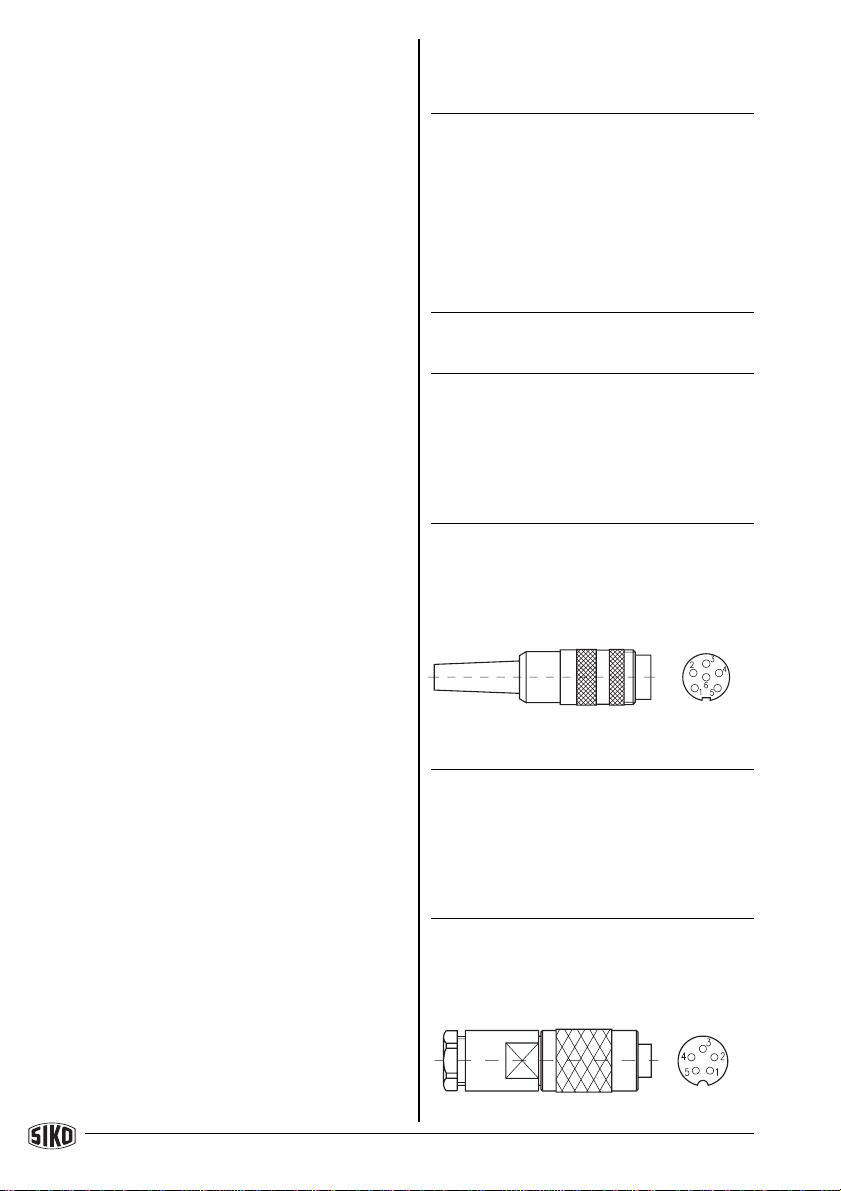
4.3 Anschlussart E4..; E6..
Anschlussbelegung PP :
Anschluss E4.. mit Kupplungsdose der Fa.
BinderSerie712.
Ansichtseite =
Lötseite
Ansichtseite =
Lötseite
IG09 Datum 25.08.1999 Art.Nr. 76363 Z.Nr. 8661031 Änd.Stand 339/99 3
Schirm
Stiftteil
Buchsenteil
PIN Farbe Belegung
1 grau GND
2 gelb Kanal A
3 weiß Kanal B
4 grün Kanal 0/I
5 braun +UB
schwarz Schirm
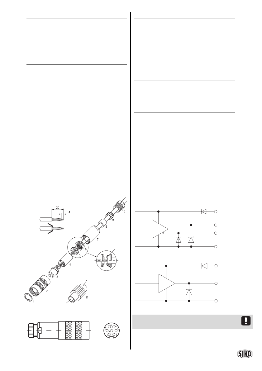
AnschlussE6..mitKupplungssteckerundKupp-
lungsdoseder Fa.BinderSerie 423.
1. Pos. 6 ... 10 über Kabelmantel schieben.
2. Kabelabisolieren.
3. Schirmumlegen.
4. Pos. 5 auf Litzen schieben.
5. LitzenanPos.3löten(entspr.Anschlussplan).
6. AbstandhülsePos. 4aufweiten undüberLit-
zenstülpen,zusammendrückenundaufPos.3
stecken.SchlitzundNut(Pos.3und4)müssen
deckungsgleichsein.
7. Pos. 6 an Pos. 5 drücken, überstehender
Schirmabschneiden.
8. Pos.2und7aufschiebenund mittelsMonta-
gewerkzeugPos.11verschrauben.
9. Pos. 8 in Pos. 9 stecken, beides in Pos. 7
schieben.
10.Pos. 10 mit Pos. 7 verschrauben.
11.Pos. 1 in Pos 2. schieben.
Abb. 2: Montage Anschlussart E6..
Ansichtseite =
Lötseite
+UB
A, B, 0
oderI
GND
1)
/A,/B,I
GND
+UB
A, B, 0
1)
PIN Farbe Belegung
1 grau GND
2 gelb Kanal A
3 weiß Kanal B
4 grün Kanal 0/I
5 braun +UB
6 N.C. N.C.
7 N.C. N.C.
schwarz Schirm
4.4AnschlussartE8..(9-pol.D-SUB)
AnschlussbelegungPP
PIN Belegung
1+U
B
2 Kanal A
3 Kanal B
4 Kanal 0/I
5 GND
6 N.C.
7 N.C.
8 N.C.
9 N.C.
5. Ausgangssignale
LD5, OP
PP
Abb. 3: Schaltung LD5, OP, PP
1) Hinweis! Die Verpolschutzdiode enfällt bei
Versionen mit UB= +5 VDC±5%.

4 IG09 Datum 25.05.1999 Art.Nr. 76363 Z.Nr. 8661031 Änd.Stand 339/99
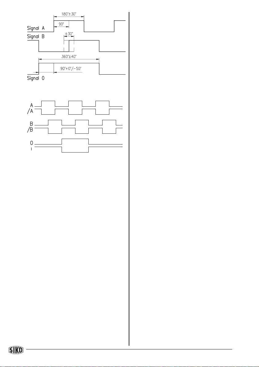
Abb.4:Phasenlage
Abb.5:SignalbildKomplementär
IG09 Datum 25.08.1999 Art.Nr. 76363 Z.Nr. 8661031 Änd.Stand 339/99 5
ENGLISH
1. Safety information
In order to carry out installation correctly, we
stronglyrecommendthisdocumentisreadvery
carefully. This will ensure your own safety and
the operating reliability of the device.
• Your device has been quality controlled, te-
sted and is ready for use. Please respect all
warnings and information which are marked
eitherdirectlyonthedeviceorinthisdocument.
• Warrantycanonlybeclaimedforcomponents
supplied by SIKO GmbH. If the system is used
togetherwithotherproducts,thewarrantyforthe
complete system is invalid.
• Repairs should be carried out only at our
works. If any information is missing or unclear,
please contact the SIKO sales staff.
2. Identification
Please check particular type of unit and type
numberfromtheidentificationplate.Typenum-
berandthecorrespondingexecutionareindica-
ted in the delivery documentation.
e.g. IG09-0023
type number
type of unit
User Information
IG09
Incremental encoder
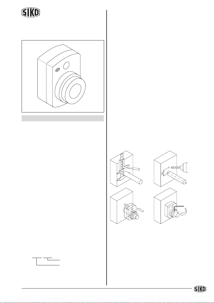
3. Installation
The unit should be used only up to the IP-
protectionlevelstated.Protecttheunit,ifneces-
sary,againstenvironmentalinfluencessuchas
sprayedwater,dust,knocks,extremetempera-
tures.
Stick gasket to encoder's mounting face. Slide
IG09 onto the solid shaft, insert torque pin into
thepreboredmountingholeandusegrubscrew
to fix the IG09's hollow shaft to the machine's
solid shaft (see fig. 1).
• Ensure sliding fit between solid shaft and
IG09.
• Ensure accurate shaft alignment and mount
theIG09withoutforce.Donotexceedthevalues
for the maximum axial and radial shaft load. If
the shaft is not correctly aligned, strain on the
bearingswill result,which maycauseoverhea-
tingandirreparabledamage.
• Especially when using torque pin type A for
fixing,ensurethat IG09doesnotjam andthatit
ismountedwithoutstrain.Pleaserememberthis
whenchoosingtheIG09'sborediameter.
• Avoid knocking the unit.
Fig. 1: Mounting instructions
If encoder IG09 is to be mounted with an inter-
mediate plate (option) first fix the plate as
describedaboveand thenmountthe encoder.
4. Electrical connection
• Switchpoweroffbeforeanyplugisinsertedor
removed!
• Any wiring must only be carried out without
power.
TorquepintypeA : pinø 6 h9
type B : bore ø 10 +0.8
6 IG09 Datum 25.05.1999 Art.Nr. 76363 Z.Nr. 8661031 Änd.Stand 339/99
• Providestrandedwireswith ferrules.
Interferenceanddistortion
Allconnectionsareprotectedagainsttheeffects
ofinterference.Thelocactionshouldbeselec-
tedto ensurethatnocapacitiveorinductive
interferences can affect the encoder or the
connection lines! Interferencecanbe caused
by motors, switch gear, cyclic controls and
contactors.Suitablewiringlayoutandchoiceof
cable can minimise the effects of interference.
When using encoders with operating voltage
+5Vensurethattheoperatingvoltagedoesnot
fallbelowthetolerancelimitortheencoderwill
notfunctioncorrectly!Incaseoflongconnection
lines (>3 m) and 5 V operating voltage it must
alwaysbeguaranteedthattheencoder'sopera-
tingsupplyis withinthedefinedtolerances!
(Safe solution: use 10-pole cable to extend
encoder's cable head; connect +UBand GND
respectively with one sense line)
The following points should be observed:
• Only screened cable should be used. Wire
cross section is to be at least 0,14 mm2, max.
0,5 mm2.
• Wiringtothescreenandground(0V)mustbe
securedtoagoodpoint.Ensurethattheconnec-
tion of the screen and earth is made to a large
surfaceareawithasoundconnectiontominimi-
seimpedance.
• The sensor should be positioned well away
from cables with interference; if necessary a
protective screen or metal housing must be
provided. The running of wiring parallel to the
mains supply should be avoided.
• Contactor coils must be linked with spark
suppression.
Powersupply
Supply voltage depends on the unit type and is
indicatedin the deliverydocumentation and on
the identification plate.
Eg.:
10 ... 30 V d.c., with polarity protection
5 V d.c. ±5% without polarity protection
4.1 Connection type E1..
Pin connection OP, LD5
Color Designation
yellow channelA
pink channel/A
white channelB
blue channel/B
green channel0
red channelI
brown +UB
grey GND
Pin connection PP
Color Designation
grey GND
yellow channelA
white channelB
green channel0/I
brown +UB
black screening
4.2 Connection type E2..
Pin connection PP :
Connection E2.. with coupling (plug); Binder
series680.
PIN Designation
1 GND
2+U
B
3 channelA
4 channelB
5 channel0/I
6 N.C.
4.3 Connection type E4..; E6..
Pin connection PP :
Connection E4.. withcoupling(socket);Binder
series712.
viewing side =
soldering side
viewing side =
soldering side

IG09 Datum 25.08.1999 Art.Nr. 76363 Z.Nr. 8661031 Änd.Stand 339/99 7
screening
pin
socket
PIN Color Designation
1 grey GND
2 yellow channelA
3 white channelB
4 green channel0/I
5 brown +UB
black screen
Connection E6.. with coupling (plug + socket);
Binderseries423.
1. Slip parts 6 to 10 over outer cable.
2. Strip cable.
3. Turndownscreening.
4. Push part 5 onto ferrules.
5. Solderstrandedwiresatpart3(followconnec-
tiondiagram).
6. Openspacer (part4) andput itoverferrules,
squeeze and push it onto part 3. Slot and
keyway of parts 3 and 4 must align.
7. Press parts 6 and 5 together; cut prodruding
screening.
8. Push parts 2 and 7 together and screw
part11usingappropriatetool.
9. Pushpart8intopart9andslidebothpartsinto
part 7.
10. Screw parts 10 and 7 together.
11. Push part 1 into part 2.
Fig. 2: Mounting of connection type E6..
viewing side =
soldering side
PIN Color Designation
1 grey GND
2 yellow channelA
3 white channelB
4 green channel0/I
5 brown +UB
6 N.C. N.C.
7 N.C. N.C.
black screen
4.4Connectiontype E8.. (9-pol. D-SUB)
Pin connection PP :
PIN Designation
1+U
B
2 channelA
3 channelB
4 channel0/I
5 GND
6 N.C.
7 N.C.
8 N.C.
9 N.C.
5. Output signals
LD5, OP
PP
Fig. 3: Output circuit LD5, OP, PP
1) Note! Encoders with UB=+5V d.c. ±5% are
withoutreversalprotectiondiode.
/A,/B,I
GND
+UB
A, B, 0
1)
+UB
A, B, 0
or I
GND
1)
8 IG09 Datum 25.05.1999 Art.Nr. 76363 Z.Nr. 8661031 Änd.Stand 339/99
Postanschrift / Postaladdress:
Postfach1106
D-79195Kirchzarten
Werk / Factory:
Weihermattenweg2
D-79256Buchenbach
Telefon / Phone 0 76 61 /394 - 0
Telefax / Fax 0 76 61 / 394 - 388
Internet www.siko.de
SIKO GmbH
DR.-ING.G.WANDRES
Fig. 4: Phase relation
Fig. 5: Signal shape inverted
Table of contents
Languages:
Other Siko Media Converter manuals


Popular Media Converter manuals by other brands


Belden
Belden GRASS VALLEY XIP-3901 user manual

Brainstorm Electronics
Brainstorm Electronics DXD Series Operation manual

Bose
Bose Wave Multi-CD Changer owner's guide

Data Translation
Data Translation DT3152-LS Getting started manual

Apogee
Apogee AD-16X user guide

CTC Union
CTC Union FIB1-10/100 series installation instructions


