manuals.online logo
Brands
  1. Home
  2. •
  3. Brands
  4. •
  5. Simrad
  6. •
  7. Marine Equipment
  8. •
  9. Simrad RF25 User manual

Simrad RF25 User manual

This manual suits for next models

1

Other Simrad Marine Equipment manuals

Simrad ES70 - REV A User manual

Simrad

Simrad ES70 - REV A User manual

Simrad TP10 User manual

Simrad

Simrad TP10 User manual

Simrad EM - TECHNICAL NOTE 2000 User manual

Simrad

Simrad EM - TECHNICAL NOTE 2000 User manual

Simrad S3009 User manual

Simrad

Simrad S3009 User manual

Simrad GO XSE Series User manual

Simrad

Simrad GO XSE Series User manual

Simrad Navico WP10 User manual

Simrad

Simrad Navico WP10 User manual

Simrad IS42J User manual

Simrad

Simrad IS42J User manual

Simrad IS20 Combi User manual

Simrad

Simrad IS20 Combi User manual

Simrad IS12 User manual

Simrad

Simrad IS12 User manual

Simrad IS42J User manual

Simrad

Simrad IS42J User manual

Simrad ES70 - DOWNLOAD AND INSTALLATION REV B User manual

Simrad

Simrad ES70 - DOWNLOAD AND INSTALLATION REV B User manual

Simrad NX40 User manual

Simrad

Simrad NX40 User manual

Simrad EQ60 User manual

Simrad

Simrad EQ60 User manual

Simrad IS40 User manual

Simrad

Simrad IS40 User manual

Simrad ES60 - DATASHEET REV A User manual
Simrad

Simrad ES60 - DATASHEET REV A User manual

Simrad BSM-2 User manual

Simrad

Simrad BSM-2 User manual
Simrad ME70 -  REV C User manual

Simrad

Simrad ME70 - REV C User manual

Simrad AP70 User manual

Simrad

Simrad AP70 User manual

Simrad SX90 - DATASHEET FOR NAVAL AND COAST GUARD REV... User manual

Simrad

Simrad SX90 - DATASHEET FOR NAVAL AND COAST GUARD REV... User manual

Simrad ES60 - DATASHEET REV A User manual

Simrad

Simrad ES60 - DATASHEET REV A User manual

Simrad SD1 Operating and maintenance instructions

Simrad

Simrad SD1 Operating and maintenance instructions

Simrad GC80 Compact MK2 User manual

Simrad

Simrad GC80 Compact MK2 User manual

Simrad ME70 -  REV C User manual

Simrad

Simrad ME70 - REV C User manual

Simrad ES80 User manual

Simrad

Simrad ES80 User manual

Popular Marine Equipment manuals by other brands

POWERWINCH 825 Operation manual

POWERWINCH

POWERWINCH 825 Operation manual

JRC JLN-628 brochure

JRC

JRC JLN-628 brochure

DIGITAL YACHT PilotLink2 Product handbook

DIGITAL YACHT

DIGITAL YACHT PilotLink2 Product handbook

Clarion CMS2 Owner's manual & installation manual

Clarion

Clarion CMS2 Owner's manual & installation manual

EBS M7000 installation manual

EBS

EBS M7000 installation manual

Kongsberg M3 Bathy installation manual

Kongsberg

Kongsberg M3 Bathy installation manual

NPK SCS-1002 operating manual

NPK

NPK SCS-1002 operating manual

Furuno FE-800 installation manual

Furuno

Furuno FE-800 installation manual

Harken 1561 instructions

Harken

Harken 1561 instructions

Notifier FS-BSO Installation and maintenance instructions

Notifier

Notifier FS-BSO Installation and maintenance instructions

Raymarine ST40 Quick reference guide

Raymarine

Raymarine ST40 Quick reference guide

Raymarine Maxiview ST80 Owner's handbook

Raymarine

Raymarine Maxiview ST80 Owner's handbook

E2S E2XS112UL Instructions/service manual

E2S

E2S E2XS112UL Instructions/service manual

GUIDANCE MARINE 20- Series Installer's guide

GUIDANCE MARINE

GUIDANCE MARINE 20- Series Installer's guide

R2Sonic 2026 Operation manual

R2Sonic

R2Sonic 2026 Operation manual

COBHAM SAILOR 6000 installation manual

COBHAM

COBHAM SAILOR 6000 installation manual

Raymarine ST60 Tridata Owner's handbook

Raymarine

Raymarine ST60 Tridata Owner's handbook

Furuno Navtex NX-700-A Operator's manual

Furuno

Furuno Navtex NX-700-A Operator's manual

manuals.online logo
manuals.online logoBrands
  • About & Mission
  • Contact us
  • Privacy Policy
  • Terms and Conditions

Copyright 2025 Manuals.Online. All Rights Reserved.

Instructions
RF25 Rudder Feedback (P/N 22014302)
GENERAL
The RF25 is designed for connection to the
SimNet network. It is equipped with
transmission link and 5 m (16 feet) of SimNet
cable with connector. It transforms the
angular travel of the rudder to a digital signal
read by the autopilot steering computer. The
RF25 transmits the rudder angle even if the
autopilot is switched off.
INSTALLATION
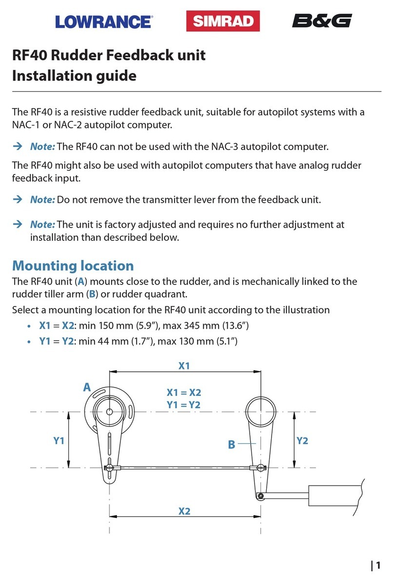
The RF25 Rudder feedback unit mounts close
to the rudder, and is mechanically linked to
the rudder tiller arm or rudder quadrant. Refer
to the figure below for recommended
mounting arrangement.
Do not remove the transmitter lever from the
feedback unit. The unit is factory adjusted and
need no further adjustment at installation than
described below.
Turn the helm to set the rudder tiller arm to
approximate centre position.
Set the mounting location to be in accordance
with the figure. The centre of the feedback
unit should be in line with the centre of the
rudder post. Mount the feedback unit to a
suitable platform using the screws provided. If
necessary, add blocking material under the
feedback unit to adjust the height of the
transmitter lever to be level with the rudder
tiller arm.
Due to space limitations, it may be necessary
to cut the length of the transmitter rod to
move the feedback unit closer to the rudder
post.
Rotate the feedback transmitter lever to
centre position. (Use the alignment mark to
line up the transmitter lever to be opposite the
cable entry into the feedback.)
Carefully observe the alignment marks. A
rudder feedback alarm may be the result if the
alignment instructions are neglected.
Note that the transmitter lever has two slots
for the transmitter link. The slots enable
maximum flexibility to provide the 1:1
mechanical linkage relationship. As a starting
point, set the transmitter rod to the inner limit
of the outer slot if possible. Drill and tap the
rudder tiller arm so that the Y1 dimension is
equal to the Y2 dimension (Use 4.2 mm drill
and 5 mm tap). Attach the ball joint to the
tiller arm, and connect the transmitter rod to
the ball joint at the rudder tiller arm.
Tighten the mounting screws for both the
feedback unit and the transmitter rod ball
joint.
Observe the feedback unit while someone
turns the helm wheel through the complete
rudder travel H.O. to H.O. and verify that the
mechanical linkage moves freely.
Page 2 of 2
ELECTRICAL CONNECTION
RF25 Rudder Feedback Unit
8-16V SimNet supply SimNet
T-joiner
SimNet backbone
SimNet drop cable
RF25 connection to SimNet
TECHNICAL SPECIFICATIONS
Dimensions:...................See figure
Weight:.........................0,5 kg (1,1 lbs)
Material: .......................Arnite T06 200 PBT
Environmental Protection: IP56
Safe distance to compass: 1,0 m (3,1 ft.)
Temperature range:
Operation:..............–25 to +55 °C
(–13 to +130 °F)
Storage:.................–30 to +70 °C
(–22 to + 158 °F)
Mounting: .....................Horizontal, vertical,
or upside down
Supply and interface: ......8-16V via SimNet
Power consumption:........0,4W
SimNet Network load factor (NL): 1
SimNet ports (input/output): 1
Cable supplied:...............5 m (16’) SimNet
cable with connector
Rudder angle: ................±120 degrees
Output signal: ................SimNet/NMEA2000
PGN127245
Accuracy: ......................±0.25° within ±5°,
otherwise ±0.5°
Repeatability:.................±0.1°
NMEA compliant
Transmitter link:.............Stainless 345 mm
(13.6") with 2 ball
joints.
Ball joint stud for rudder arm requires 4.2 mm
diameter hole and 5 mm tap.
SPARE PARTS
22014286 RF25 Rudder Feedback
w/accessories
20193454 Transmitter link
44133122 Transmitter rod
M5x325mm
20193624 Ball joint Ass'y (2)
RF25 Dimensions
Transmitter Link – dimensions
20222552 / A