SORG Dynamis TSD Service manual

Service record Dynamis TSD 1 of 36
2021-05-26 Besondere Menschen, besondere Lösungen.
EN
Unique people, unique solutions
Service record Dynamis TSD
Service recordService record
All individual adjustments to the wheelchair are described below.
Tools and specialist knowledge are required for these settings. Please
leave these adjustments to a qualied rehabilitation specialist.
Dynamis TSDDynamis TSD

2 of 36 Service record Dynamis TSD
Service record Dynamis TSD 2021-05-26
Imprint
SORG Rollstuhltechnik GmbH + Co. KG
Benzstraße 3-5
68794 Oberhausen-Rheinhausen / Germany
Fon +49 7254-9279-0
Fax +49 7254-9279-10
Mail [email protected]
Web www.sorgrollstuhltechnik.de
Revision status
2021-05-26
Technical status
We reserve the right to make technical chan-
ges and misprints. The images can dier from
the actual individual equipment components.
The handling is to be carried out accordingly.
Gender notice
For editorial reasons for better readability, only
the masculine form is used. Corresponding
terms apply in the sense of equal treatment to
all genders and do not represent any valuation.
Copyright
All content, especially texts, photographs and
graphics, are protected by copyright. All rights,
including reproduction, publication, editing
and translation, are reserved. © by SORG
Rollstuhltechnik GmbH+Co. KG Benzstraße 3-5,
68794 Oberhausen-Rheinhausen / Germany.
You can nd our general terms and condi-
tions on our order forms and at www.sorgroll-
stuhltechnik.de/impressum.

Service record Dynamis TSD 3 of 36
2021-05-26
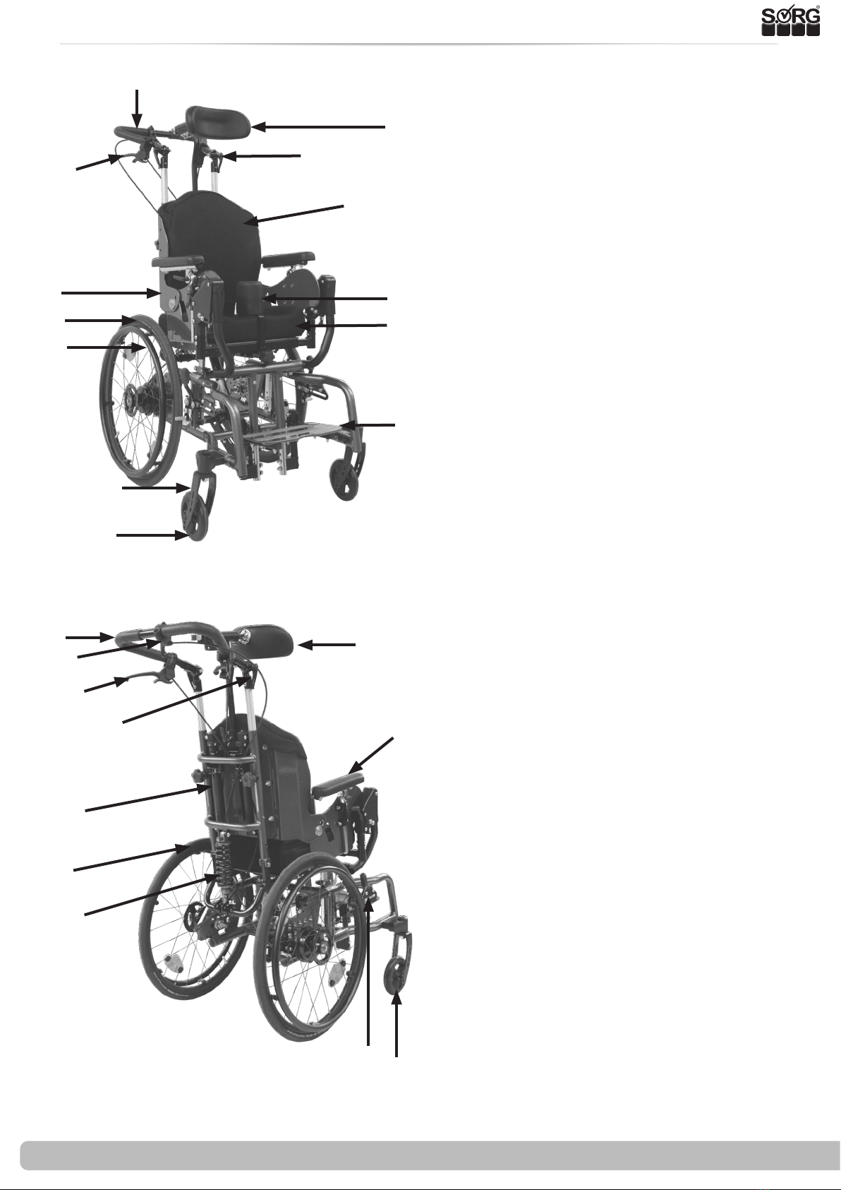
1 Wheelchair overview 4
2 General information 5
2.1 General information service record 5
2.2 Documentation indications 5
2.3 Required torques and tools 5
2.4 Explanation of symbols 6
2.5 General safety instructions 7
3 Assembly groups 8
3.1 Assembly group wheels 8
3.1.1 Wheel position 8
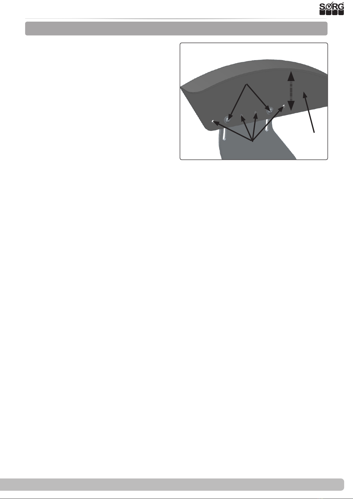
3.1.2
Adjusting the height and position of the
wheel cover when the wheel changes position 9
3.1.3 Moving the wheels WITHOUT camber
adapter (20",22",24") 10
3.1.4 Moving the wheels WITH camber ad-
apter (20",22",24") 10
3.1.5 caster wheels 11
3.2. Assembly group frame 12
3.2.1 Frame widening 12
3.3 Assembly group seat 13
3.3.1 Vertical adjustment of the seat
height 13
3.3.2 Conversion to double gas pressure
spring 14
3.4 Assembly group back 17
3.4.1 Setting dynamic back 17
3.4.2 Setting the rebound speed 17
3.5 Assembly group leg support 18
3.5.1 Adjusting the leg support 18
3.5.2 Adjusting the depth 18
3.5.3 Adjusting the height 19
3.5.4 Presetting the opening angle 19
3.5.5 Height adjustment of the calf support 19
3.5.6 Height adjustment of the footrest 20
3.6 Assembly group ERGO-seat 21
3.6.1 General information about the ERGO-
seat 21
3.6.2 Removing the ERGO-seat 21
3.6.3 Axis of rotation seat part / back part 22
3.6.4 Growth in seat depth ERGO-seat 22
3.6.5 Increase seat width ERGO seat
and back unit 23
3.7 Assembly group brakes 24
3.7.1 Drum brake 24
3.7.2 Knee lever brake 25
3.8 Assembly group frame accessories 26
3.8.1 Anti tipper 26
3.8.2 Step tube 26
3.9 Assembly group headrest 27
3.9.1 Height adjustment 27
3.9.2 Depth adjustment and dynamics of the
headrest 27
3.9.3 adjusting the inclination 27
3.10 Assembly group abduction wedge 28
3.10.1 Depth adjustment 28
3.10.2 Height adjustment 28
3.11 Assembly group lateral support 29
3.11.1 Nomenclature 29
3.11.2 Vertical adjustment 29
3.11.3 Horizontal adjustment 29
3.11.4 Fine adjustment of the pad holder 30
3.11.5 Adaption to the user 30
4Repairs / maintenance / re-use 31
4.1 Repairs 31
4.2 Spare parts 31
4.3 Cleaning 31
4.4 Disinfection 31
4.5 Storage 31
4.6 Lifespan 32
4.7 Reinstatement 32
4.8 Disposal 32
4.9 Maintenance / Inspection 32
5 Technical data 34
5.1 Data and measurements 34
5.2 Meaning of labels 35
5.3 Declaration of conformity 35
Contents

4 of 36 Service record Dynamis TSD
Service record Dynamis TSD 2021-05-26
1 Wheelchair overview
1 Push bow
2Headrest
3Drum brake control lever
4 Eccentric levers for angle adjustment
5 Molded back cushion
6 Ergo Seat
7Abduction wedge
8Wheel
9Molded seat cushion
10 Handrim
11 Footplate
12 Caster fork
13 caster wheel
14 Push bow
15 Headrest
16 Release lever for seat tilt
17 Control lever for drum brake
18 Star handle for height adjustment,
push handle
19 Armrests
20 back guide
21 Wheel
22 Shock absorbers
23 brake lever of the knee lever brake
24 caster wheel
1
5
6
9
7
12
13
22
21
19
4
3
18
17
16
2
23 24
15
20
11
8
10
14

Service record Dynamis TSD 5 of 36
2021-05-26
2 General Information
All individual settings, adjustments, repairs and the annual inspection of the wheelchair are
described below. This requires tools and special expertise. Please leave these adjustments to a
qualied specialist retailer.
Adjustments that can be made by the attendant are described in the instructions for use.
If you have any questions or comments, please contact your specialist retailer or our team (+49
7254 9279-0).
Please note:
• Information for the user can be found in the instructions for use
• Maintenance instructions can be found under: Chapter 4 (Repairs & Maintenance)
• M5: 5 Nm;
• M6: 7 Nm;
• M6 (perforated plate) 10 Nm
• M8: 20 Nm;
• M10 (nut): 25 Nm; (caster wheel)
• thru axle tting 40 Nm
• Torque wrench (5-50 Nm)
• Open-ended wrench
• Reversible ratchet with socket wrench inserts
• Hexagon screwdriver
• Phillips screwdriver
• Flat-blade screwdriver
• Plastic hammer
• Side cutter
• Thread locking liquid
• Bicycle tube repair kit
• Workbench / vice with plastic jaws
• Special open-end wrench for adjusting the shock absorber
2.1 General information service record
2.2 Documentation indications
2.3 Required torques and tools
Torque required for the following screws:
Needed tools:

6 of 36 Service record Dynamis TSD
Service record Dynamis TSD 2021-05-26
2 General information
2.4 Explanation of symbols
DANGER! Warnings for personal
safety issues, of utmost impor-
tance
CORRECT safety-relevant setting
/ handling
INCORRECT setting / handling
FORBIDDEN
Reference to additional / further
reading.
Set or adjust the angle
Open / close
Turn clockwise
Rotate counter clockwise
Steps to be performed at the
same time
Steps to be performed in se-
quence
Steps to be performed on both
sides
Handling
(A); (B)
1. 1.
1. 2.
;
2x2x
Push / pull / insert / move / re-
move
Push in a certain direction
Important detail / element
Correct or proper setting / use
Inadmissible or incorrect setting
/ use
Reference from text to detail
Point of view
View from above
Side view
View from below
Front view
Reat view
Attach a part
Remove a part

Service record Dynamis TSD 7 of 36
2021-05-26
2 General information
2.5 General safety instructions
Check before every trip:
• Frame, back unit, add-on parts and accessories for visible damage, bends, cracks or mis-
sing / loose screws,
• Wheels / thru axles on tight t ,
• sucient tire pressure, tire prole,
• Functionality of the brakes,
• tight t of the angle adjustment elements / eccentric clamps,
• rm closure of the seat plate / back / foot plate,
• Functionality of the anti-tipper / seat and back straps,
• whether all previously dismantled parts are reinserted and rmly locked.
There is a risk of injuries (e.g. crushing) on all rotating, rotatable or foldable parts, also
during adjustment and repair work as well as during transport.
All wheelchair parts are to be handled properly. Do not throw or drop removable parts!
Before starting the check, repair or adjustment work, clean / disinfect the wheelchair and
secure it against tipping over and / or falling.
Use only original spare parts.
Safety nuts may only be used once. Safety nuts that have been loosened must be repla-
ced with new ones.
Only regular maintenance of all safety-relevant parts on the wheelchair by a qualied
rehab workshop protects against damage and maintains our manufacturer's warranty.
Lifespan
Use beyond the specied service life leads to an increase in the residual risks and should
only be carried out after careful, qualied consideration by the operator. If the service life is
reached, the user or a responsible person should contact the specialist retailer. There you can
get information about the possibility of reconditioning the product.
Combination with products from other manufacturers
The wheelchair may only be combined with the additional electrical drives approved by the
manufacturer. Restrictions or adjustments as well as the cultivation itself are the responsibility
of the provider of the additional system or the commissioned specialist trade. Please ask the
manufacturer of the additional drives for the requirements.
In the combination of a wheelchair and an additional electric drive, particular loads oc-
cur that can lead to damage to the wheelchair. Approach obstacles only slowly and over-
come them carefully so that little force is exerted on the steering wheel, drive wheel and the
wheelchair as a whole.

8 of 36 Service record Dynamis TSD
Service record Dynamis TSD 2021-05-26
3.1 Assembly group wheels
3.1.1 Wheel position
Seat height adjustment up to seat depth 32 & 34 (size 1)
(Frame parts size 1/2)
Seat height adjustment from seat depth 50 (size 4)
Seat height adjustment up to seat depth 48 (size 1 - 3)
(Frame parts size 1/2 and size. 3)
16" 20" 22" 24"
45 cm 43 cm 45 cm 48 cm
X45,5 cm 47,5 cm 50,5 cm
X47,5 cm 50 cm 52,5 cm
16" 20" 22" 24"
47,5 cm 41 cm 43 cm 46 cm
X43,5 cm 45,5 cm 48 cm
X45,5 cm 48 cm 50,5 cm
16" 20" 22" 24"
49,5 cm 43 cm 45 cm 48 cm
X45,5 cm 47,5 cm 50,5 cm
X 48 cm 50 cm 53 cm
+2/+4cm
+2/+4/+6cm
+2/+4cm
Inner hole for
tilt protection
Standard position
For larger seat heights: primarily adjust
via the position of the wheel. With 24 "wheel
mounted at the bottom: anti-tipper 26"
mounted in the inner holes.
After all position changes, check the tilt
stability with the patient when fully tilted and
modify the position if necessary!
Standard position
Standard position

Service record Dynamis TSD 9 of 36
2021-05-26
3.1 Assembly group wheels
(3)
(B)
(A)
(C)
3.1.2
Adjusting the height and position of the wheel cover when the wheel changes position
(3) With vertical adjustment:
• Remoce wheel,
• Loosen the screw connections (A) on the
side guard
• andpush the side guard (B) all the way
up.
• Adjust the wheel position.
• Reinsert the wheel
• and slide the side guard (B)into the re-
quired position. Then remove the wheel
gain
• and tighten the screws (A) on the side
guard (B) again.
With horizontal adjustment:
• Remove wheel,
• Remove the screw connection (A) on
the side guard (B).
• Move the side guard (B) into the alternative holes (C) according to the desired position
of the wheel and screw it on a little so that the height of the side guard can still be mo-
ved.
• Then proceed according to the vertical adjustment.

10 of 36 Service record Dynamis TSD
Service record Dynamis TSD 2021-05-26
3.1.3 Moving the wheels WITHOUT camber adapter(20",22",24")
(A)
(B)
(1)
3.1 Assembly group wheels
(2)
(A)
(C)
(D)
(E)
(B)
3.1.4 Moving the wheels WITH camber adapter (20",22",24")
• (2) Remove the wheels and the hex nut
(A) from the thru axle tting (B),
• remove the nut (C) of the brake coun-
ter-holder (D) including the inner slee-
ve,
• Remove both lintel adapters (E) and
place them in front of the new position.
• Fix both lintel adapters (E) in the new
position with the tting (B) and the
sleeve,
• Put the hexagon nut 35 Nm (A) back on
and tighten it,
• Put on the nut (C) of the drum brake
counter holder and tighten it.
Correct the position of the knee lever
brake and then check that it is working pro-
perly.
The lintel adapters must always be
mounted "in opposite directions". At 0 °:
inside = thick end below / outside = thick
end above.
• (1) Remove the wheels and the hex nut
(A) from the thru axle tting (B),
• Place the tting (B) in the new hole,
• Put the hexagon nut 35 Nm (A) back
on, tighten it and insert the wheels
again.
Correct the position of the knee lever
brake and then check that it is working pro-
perly.

Service record Dynamis TSD 11 of 36
2021-05-26
3.1 Assembly group wheels
3.1.5 Caster wheels
(1)
(B)
(C)
(A)
(2)
(A)
To adjust the steering wheel adapter:
• (1) loosen the screw (A), also the one
on the inside of the frame, with which
the adapter is attached to the frame
tube,
• loosen the screw (B),
• bring the adapter into an exactly ver-
tical position by turning the adjusting
washer (C) (with a slotted screwdriver),
• check the position by creating an angle.
• tighten all screws tightly again; Screws
(A) with 9 Nm, screw (B) with 7 Nm
The steering head inclination must be readjusted after every change to the wheel.
Safety nuts may only be used once. Safety nuts that have been loosened must be repla-
ced with new ones.
An incorrectly set steering head inclination leads to annoying and cumbersome "uphill
and downhill ride" when cornering due to the wheel caster.
To replace the steering wheels:
• (2) loosen the screw (A) on both sided,
• remove the caster wheel,
• put the new caster wheel on the sleeves.
• Then set up the appropriate distances
for the existing caster fork / - wheel
combination
• and tighten the screws (A) again.
Depending on the size of the new caster wheel, the caster fork may also have to be replaced.
Note:

12 of 36 Service record Dynamis TSD
Service record Dynamis TSD 2021-05-26
3.2.1 Frame widening
3.2 Assembly group frame
(1)
(A)
(B)
(B)
(2)
(A)
(3)
To widen the frame, rst remove the Ergo seat.
(see chapter Ergo seat assembly 3.6.2.).
To widen the frame:
• Remove both wheels.
• Remove the screw connections of the
crossbars (1A+2A) on one side.
• Remove the screw connection of the
pivot point. (3A)
• Now pull the frame apart (1B+2B)(half
the desired widening)
• and reinsert the screw loosely.
• Move the sockets at the pivot point (eit-
her one or two sockets on the left and
right) (3B/3C). Now screw the previous-
ly loosened screws back on.
• Proceed in the same way with all screw
connections on the opposite side.
• then tighten the screws again.
The traverses must be oset at the
same distance on both sides.
(B) (B)
(A)
(B) (B)
(C) (C)

Service record Dynamis TSD 13 of 36
2021-05-26
3.3 Assembly group seat
3.3.1 Vertical adjustment of the seat height
In addition to the possibility of dening the
seat height through the positioning and size
of the drive and steering wheels, it can also be
changed by vertically moving the seat plate.
For changing the seat height in 20 mm steps
with the same tilting path:
• (1) Loosen both screws (C)of the guide
clamp on both sides and
• completely remove both screws of the
screw connection (A) of the seat unit in-
cluding the saddle washers (B) on both
sides.
• (2) Completely remove the screw con-
nection of the gas pressure spring (F)
incl. the sleeves.
• (2) Move the seat unit with the brackets
(D) by the desired dimension in the
drilling pattern (E) (by ± 20 mm/ 2 cm
per hole),
• (2) move tha gas spring in the hole pat-
tern (G) (by ± 20 mm/ 2 cm per hole) to
the same extent.
• Insert the screws (1A) with the saddle
washers (1B) in the new position and
tighten them tightly.
• Insert the screw (2F) with the sleeves
into the connection of the gas pressure
spring and tighten them tightly.
(1)
(2)
(A)
(C)
(D)
(E)
(B)
(F)
After every change to the seat unit and
/ or the tilt, the tilting behavior of the Dyna-
mis TSD must be retested and practiced with
the occupant and the support of an experi-
enced, strong helper.
If you do not move the seat unit with
the gas pressure spring in parallel, the result
is a wrong tilting path and possibly a die-
rent seat inclination, which endangers the
tilt stability of the Dynamis TSD.
(see table on page 8)

14 of 36 Service record Dynamis TSD
Service record Dynamis TSD 2021-05-26
3.3 Assembly group seat
3.3.2 Conversion to double gas pressure spring
(1) (A)
(E)
(F)
(G)
(G)
(D)
(B)
(H)
(C)
Step 1: Remove the Ergo seat:
• Remove the Ergo seat according to
chapter 3.6.2.
Step 2: Control lever
• (1) Remove the two screws (A) of the
operating lever and the spiral cable
sheath from the bowden cables.
Step 3: Relocate the gas pressure spring
• (2) Remove the upper mounting of the
gas pressure spring with the screws (A).
• (3) Remove the two screws (A).
• Move the mount (B) including the gas
pressure spring (C) into the alternative
holes (D).
• (4) Move the upper mount (A) into the
alternative holes (B).
• (5) Remove the inner cable of the bowden
cable (A) on the realease mechanism of
the gas pressure spring by loosening the
clamping nipple (B) and the adjusting
screw (C) and / or the lock nut (D) and pull
out the complete bowden cable (A).
Step 5: Insert new lower mounts
• (6) Attach the second lower mount (A) of
the gas pressure spring to the two cross
members (B) and
• screw the mount with the screws (C)
tightly into the prepared holes in the
crossbars (3D).
(A)
(C)
(B)
(D)
(D)
(3)
(A)
(2)
(4)
(A)
(B)
(C)
(B)

Service record Dynamis TSD 15 of 36
2021-05-26
3.3 Assembly group seat
(7) (A)
(5) (A)
(C) (D) (B)
(B)
(A)(A)
(C)
(C)
(6)
Pay attention to the symmetry of the attach-
ment of the crossbar adapters (right and left
side in the same hole!).
Step 7: Assemble the upper mounts
• (7) Screw the second upper mount (A)
of the gas pressure spring with the two
screws (B) under the seat plate into the
prepared holes.
Step 8: Mount new gas pressure spring on top
• (8) Screw the gas pressure spring to the
upper mount (A) with the screw (C).
Step 9: Mount new gas pressure spring below
• (9) Screw the gas pressure spring tinto
the lower mounts with the screw (A) in
the prepared holes (B).
(9)
(B) (B)
(A) (A)
(8)
(A)
(B)
(C)
(B)
Both gas pressure springs must be installed in
the same assembly points on the mount.
Use the same mounting points as before.
Otherwise there will be an incorrect tilting
path.
Step 10: AScrew the release lever back on
• Mount the new release lever for the gas
pressure springs on the push bar again.

16 of 36 Service record Dynamis TSD
Service record Dynamis TSD 2021-05-26
3.3 Assembly group seat
Step 11: Set the maximum length of the bow-
den cable
• Set the push bow to its maximum push
height,
• (10) fold the back of the Dynamis TSD
forward around and
• lalso place the push bow forward to-
wards the legrest (see illustration) so
that you get the maximum length for
the bowden cable.
• Now guide the new Bowden cable from
the release lever over the seat to the
rear and then back to the front under
the Dynamis TSD to the respective re-
lease device of the gas pressure springs.
• Fold the back of the Dynamis TSD back
into a vertical position and
• cut the outer sleeves of the two Bow-
den cables to the required size.
•
Step 12:
• (10) Fold the back of the Dynamis TSD
back into a vertical position
•
Step 13: Mount bowden cables
• (11) Mount the ends (A) of the two
inner cables to the release mechanism
of the gas pressure springs.
• First thread the inner cables (B) through
the adjusting screw (C), then through
the hole (D) of the clamping nipple (E).
• Use your thumb to push the release le-
ver (A) a little up towards the adjusting
screw (C).
• Tighten the clamping nipple (D) while
pressing the release lever upwards.
• (12) Shorten the protruding piece of
the bowden cable (A) just enough so
that you can readjust the release torque
with the clamping nipple if necessary.
(12)
(11)
(A)
(B)
(C) (D) (E)
(B) (C)
(A)
After every change to the seat unit and / or the tilt, the tilting behavior of the Dynamis
TSD must be retested and practiced with the occupant and the support of an experienced,
strong helper.
Step 14
• Check the functionality of the release
mechanism and adjust the release
torque using the adjusting screw (12 B)
and the lock nut (11C).
Step 15:
• Reinstall the Ergo seat.
(10)

Service record Dynamis TSD 17 of 36
2021-05-26
3.4.1 Setting dynamic back
The back dynamics of the Dynamis TSD can be adjusted very easily with the included SORG
open-end wrench (1) With just a few simple steps you can increase or decrease the counterforce
of the suspension.
Please note the following steps:
1. Increase the counterforce (2): Turn the adjusting nut to the right with the help of the SORG
open-end wrench. This increases the dynamism of the back.
2. Reduce the counterforce (3): Turn the adjusting nut to the left with the help of the SORG
open-ended spanner. This weakens the dynamic of the back.
The nut must always be screwed in at least so far that the steel spring is somewhat pre-
tensioned.
3.4 Assembly group back
3.4.2 Setting the rebound speed
The rebound speed is the speed at which the patient is brought back to the starting position.
The speed of the rebound can be increased or decreased.
Please note the following steps:
1. Accelerate rebound: Turn the red button
counterclockwise to the left to accelerate the
rebound speed.
2. Slowing down the rebound: Turn the red
button clockwise to the right to slow down the
rebound speed.
(1)
(2) (3)

18 of 36 Service record Dynamis TSD
Service record Dynamis TSD 2021-05-26
3.5 Assembly group leg support
3.5.1 Adjusting the leg support
The legrest, which can be swiveled upwards, is
mounted under the seat frame with the aid of
a traverse and clamping screws.
1. When adjusting the legrest, make sure that
the axis of rotation of the legrest (A) is as close
as possible to the anatomical axis of rotation
of the user's knee.
After every change to the legrest, check whether the caster wheels can still turn freely
through 360 ° when tilted to the front. You may have to make corrections either using the
caster wheels or the leg rests.
(A)
3.5.2 Adjusting the depth
1. Loosen the clamping screws (A) on the seat
frame, then
2. Adjust the depth as desired.
3. Tighten the screws again and check.
The depth of the legrest can be continuously adjusted up to 8 cm. To do this, please follow the
steps below:
(A)

Service record Dynamis TSD 19 of 36
2021-05-26
3.5 Assembly group leg support
3.5.3 Adjusting the height
1. Remove the screws (A) on the journal part,
2. Adjust the height as desired by lifting and
3. Replace the screws, tighten them and then
check them.
The height of the legrest can be continuously
adjusted to 1.5 or 3 cm. To do this, please fol-
low the steps below: (A)
3.5.4 Presetting the opening angle
The opening angle of the legrest can be ad-
justed continuously between 90 ° and 117 ° as
follows:
1. Engage the pull latch by turning it 90 ° (A)
2. Loosen the screws (B) on the grid plate on
both sides, inside and outside.
3. Adjust the legrest to the desired position.
4. Tighten the screws again rmly.
(A)
(B)
3.5.5 Height adjustment of the calf support
To change the height of the calf support, ple-
ase follow the steps below:
1. Loosen the screws. (1A)
2. Now move the calf clamping plate and at-
tach the removed elements in reverse order.
3. Make sure that all screws are properly tigh-
tened.
(A)
(1)
Height adjustment not possible in combination with an abduction wedge.

20 of 36 Service record Dynamis TSD
Service record Dynamis TSD 2021-05-26
Setting the distance between the foot and seat
plate (LLL)
With the standard legrest, the distance bet-
ween the upper edge of the seat plate and
the upper edge of the footplate is changed as
follows:
• (2) Remove the screws (A),
• remove the footplate / s and
• move the footplate/s along the holes
(B) to the new position.
• Reinstall the two screws (A) and tighten
them tightly.
Setting the stop angle of the footplate/s
(3) Use the two adjusting screws (B) to adjust
the stop angle of this footplate/s.
• Fold the footplate/s back,
• loosen the lock nuts (A),
• turn the two adjusting screws (B), until
you have reached the desired angle,
• tighten the lock nuts (A) again.
(2) (A)
(B)
(A)
(B)
(C)
(3)
3.5 Assembly group seg support
3.5.6 Height adjustment of the footrest
Distance from the
upper edge of the
seat plate to the
upper edge of the
footplate
When the footplate/s are in use, both
adjusting screws must lie rmly against the
tubes (C) of the leg support. It is essential to
avoid an uneven contact point for the adjus-
ting screws.
(1)
(4)
(A)
Alternatively:
1. Remove the screws (4A)
2. and bring the stirrup to the desired height.
3. Screw in the screws (4A) and the stop parts
(4B) up to the outer tube.
4. Now pull the stirrup down a little
5. and screw in the stop part (4B) completely. (B)
Other manuals for Dynamis TSD
1
Table of contents
Other SORG Wheelchair manuals

SORG
SORG Tilty vario User manual

SORG
SORG Jump alpha Service manual

SORG
SORG Dynamis TSD User manual

SORG
SORG MIO MOVE Service manual

SORG
SORG Jump beta User manual

SORG
SORG Jump alpha User manual

SORG
SORG Tilty vario Service manual

SORG
SORG Tilty vario User manual

SORG
SORG Mio User manual

SORG
SORG Loop Service manual

SORG
SORG Loop 802 User manual

SORG
SORG Mio Move 604 User manual

SORG
SORG Vector Service manual

SORG
SORG MIO MOVE Service manual

SORG
SORG Airon 792 User manual

SORG
SORG Mio Carbon Service manual

SORG
SORG Jump alpha Service manual

SORG
SORG Vector User manual

SORG
SORG Dynamis MV Service manual

SORG
SORG Siro II User manual