Jump alpha
8
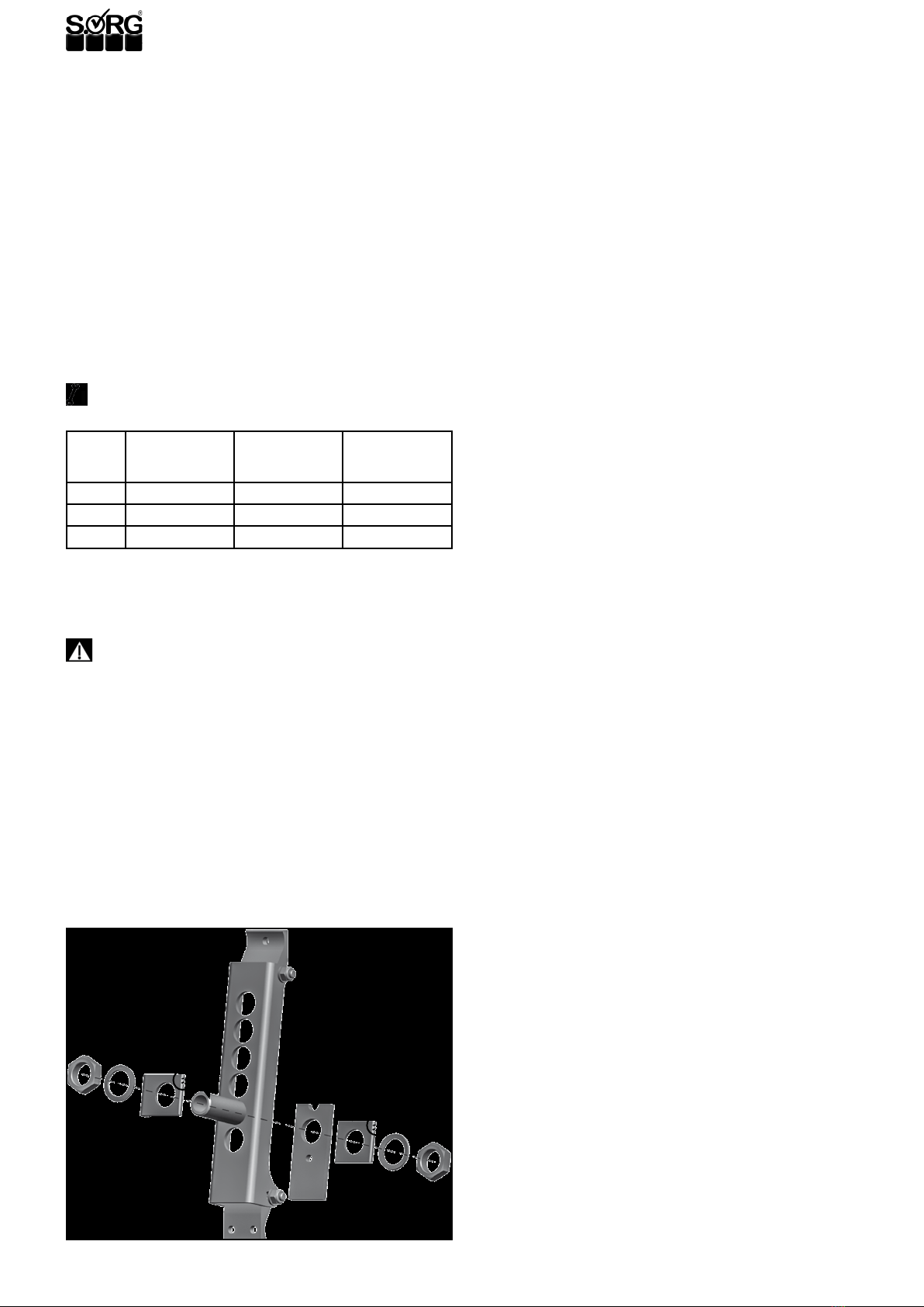
2.3.3 Seat height in back, seat slant
ATTENTION
After each change made on the rear wheels the function-
ality of the wheel lock must be checked and the casters
must be newly adjusted.
Generally, the seat height in back is about 2-3 cm lower as
in front, for a safe and comfortable seat position with a good
distribution of the seat pressure and to avoid a “sliding out”.
However, other settings in individual cases can also be use-
ful.
• (1) Remove the rear wheels,
• remove the side guards/skirt guards with the
screws (A) (easily remove the desk side guard)
• (2) remove the quick-release axle tting including
all washers in the alternative holes (C)
• and retighten all screws. (tightening torque nuts
M18 tting 35Nm).
• Mount the side guards and place the rear wheels
back in the quick-release axle.
�INDICATION
The ttings must stick out of the perforated plate at the
same length on both sides. The ttings can only stick out
so that the side distance of the tires to the side guard is
as low as possible, however a min. of 10mm.
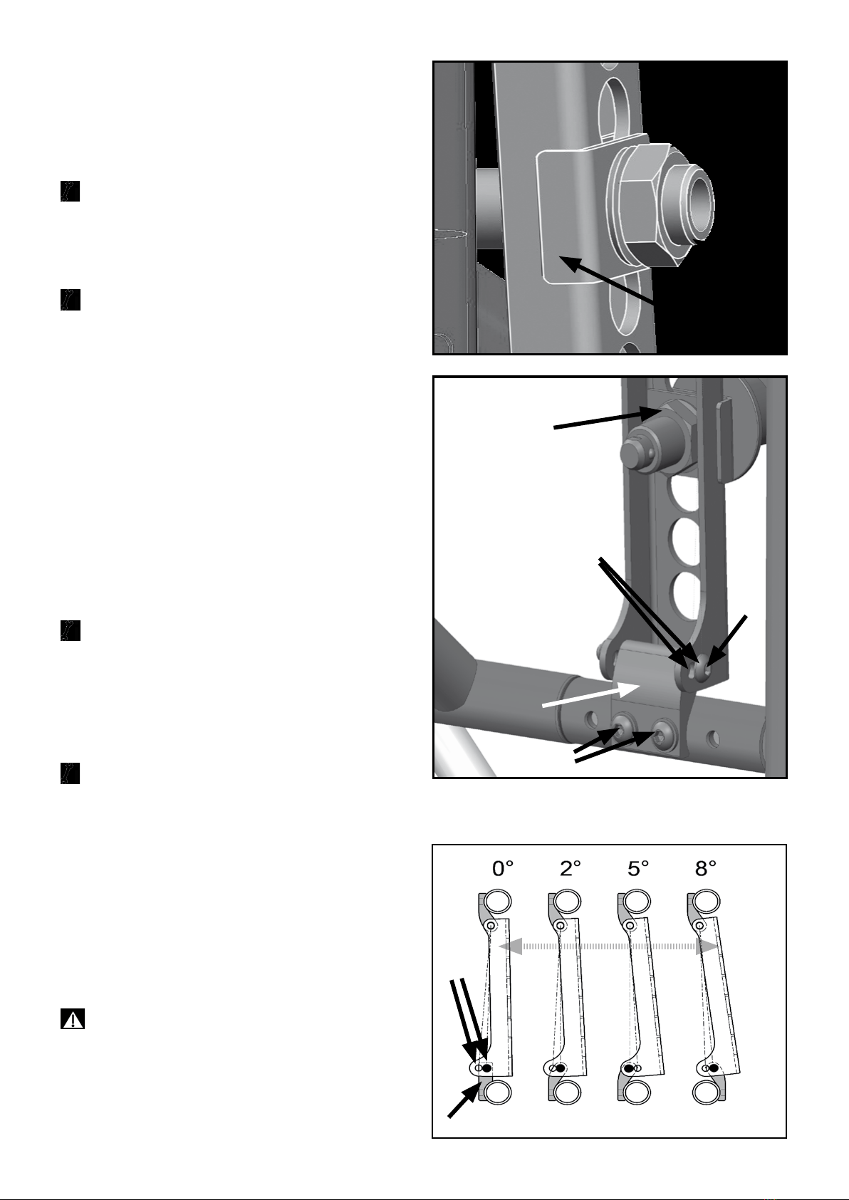
2.3.4 Steering head slant
ATTENTION
After every change on the rear wheel, the steering head
slant must be newly adjusted.
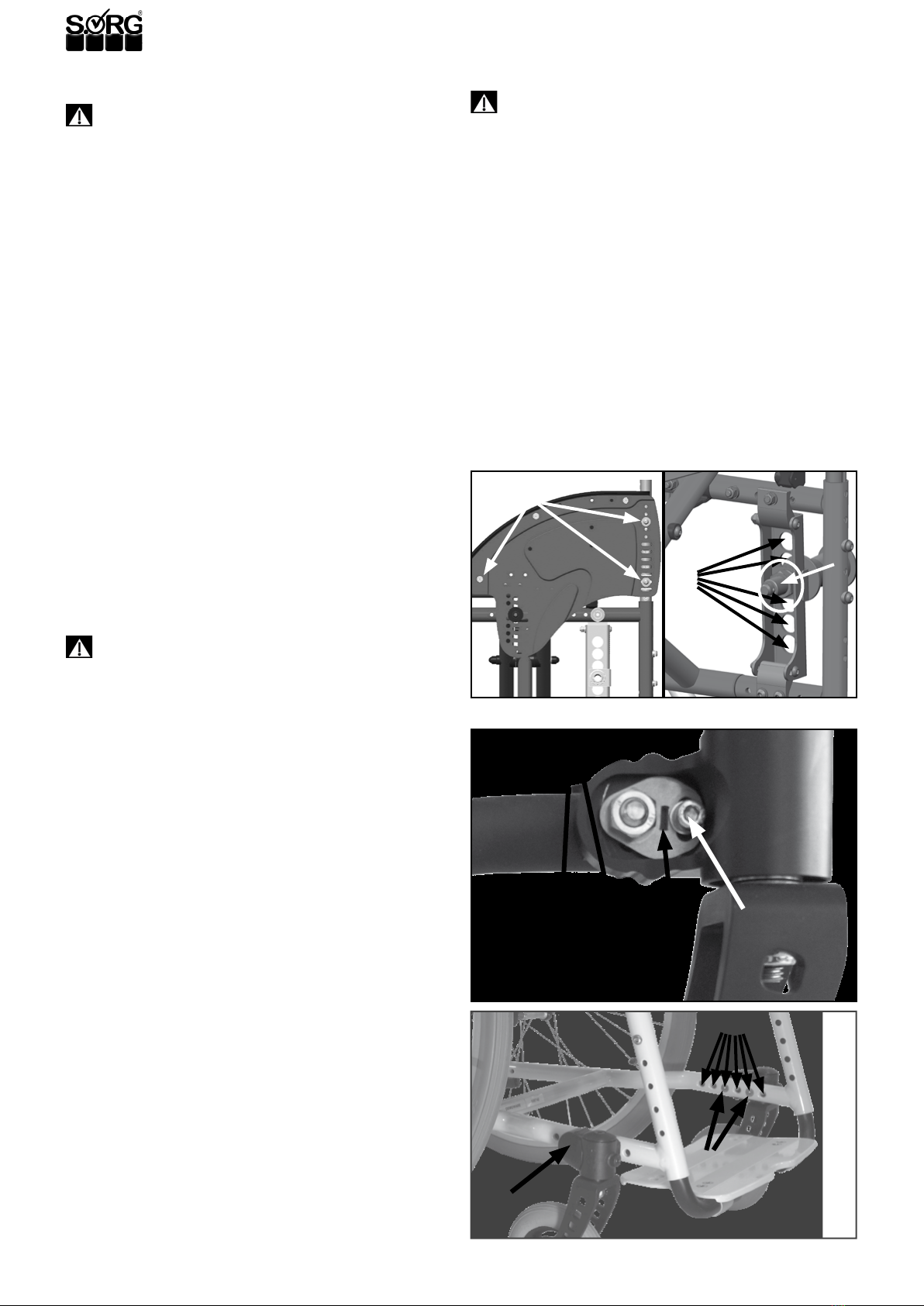
To adjust the caster adapter:
• (3) loosen all screws (A) on both (!) sides,
• loosen both screws (B).
• By tuning the adjust washer (C) (with a at head
screw driver) place the adapter in a vertical posi-
tion (using an angle).
• Retighten all screws; screws (A) with 9 Nm, screw
(B) with 7 Nm.
�INDICATION
A falsely set steering head slant can lead to the casters
shaking back and forth and can lead to hindering curve
rides (from casters).
2.3.5 Replacing/displacing the caster adap-
ters and casters
• (4) Remove the caps (A) on both sides,
• remove all screws (B) on both sides
• and remove also the distance pieces, if necessary.
• Replace the caster adapters with new ones and/or
displace them in the alternative holes (C).
• Replace all screws (if necessary also the distance
pieces) and tighten them; screws (A) with 9 Nm,
screw (B) with 7 Nm.
• Check the steering head slant (see 2.3.4)
In order to move the casters in the fork, proceed as de-
scribed in 2.3.2.
2.3.6 Removable rear wheels
ATTENTION
No person can be sitting in the wheelchair while mount-
ing/demounting the wheels. It must be supported and tip
safe, on rm ground and has to be secured against rolling
away and tipping over.
To remove/apply the rear wheels press the locking knob in
the wheel hub.
(3)
(B)
(C)
(A)
(4)
(A)
(B)
(C)
(A)
(1) (2)
(C)
(B)