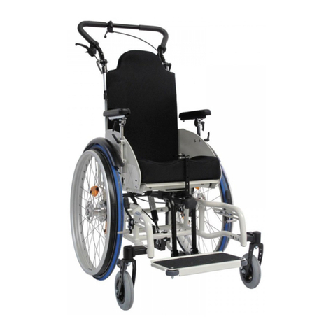
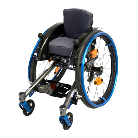
SORG MIO MOVE Service manual

service record
1
Mio
Move
service record
for your rehab technician

Mio Move
2
IMPRINT
SORG Rollstuhltechnik GmbH+Co.KG
Benzstraße 3-5
D-68794 Oberhausen-Rheinhausen
Tel. +49 7254-9279-0
Fax +49 7254-9279-10
E-mail info@sorgrollstuhltechnik.de
Web www.sorgrollstuhltechnik.de
REVISION STATUS
Revision: 2018-09-25
TECHNICAL STATUS
Technical changes and misprints reserved. The pictures in
this user manual can – depending on the individual equip-
ment – differ from the actual equipment components. How-
ever, a corresponding conduction is possible.
rehaKIND
We are a member of rehaKIND e.V.
International association
child and adolescent rehabilitation
COPYRIGHT
© by SORG Rollstuhltechnik GmbH + Co. KG Benzstraße
3-5, 68794 Oberhausen-Rheinhausen.
All texts and pictures in this user manual underlie the
international copyright protection and are not allowed to be
published without our consent – not even in excerpts!
CERTIFICATION
Our Quality Management System is certied according to
the ISO 9001:2015 under the certicate no. 12 100 20070
TMS.

service record
3
IMPRINT 2
REVISION STATUS 2
TECHNICAL STATUS 2
rehaKIND 2
COPYRIGHT 2
CERTIFICATION 2
wheelchair overview 4
1 PREAMBLE 4
1.1 GENERAL INFORMATION 4
1.2 SIGN EXPLANATION 4
1.3 RECEPTION 4
1.4 SERVICE AND MAINTENANCE 5
1.5 DOCUMENTATION 5
1.6 ACCESSORY AND ATTACHMENT
DRIVES 5
1.7 ADJUSTMENTS ON THE WHEELCHAIR 5
1.8 TIGHTENING TORQUE AND TOOLS 5
1.9 WORD EXPLANATION 5
2 ADJUSTMENTS ON
THE WHEELCHAIR 6
2.1 ASSEMBLY GROUP WHEELS 6
2.1.1 Centre of gravity/ active
level/seat height 6
2.1.2 Camber 6
2.1.3 Casters 6
2.2 ASSEMBLY GROUP SEAT 7
2.2.1 Tilting 7
2.2.2 Changing the seat position 7
2.2.3 Changing the seat width 8
2.2.4 Changing the seat depth 9
2.2.5 Blocking the tilting 9
2.3 ASSEMBLY GROUP BACK 10
2.3.1 Changing the back height 10
2.3.2 Replacing/removing the
curved back plate 10
2.3.3 Bracket tabs for the
curved back plate 10
2.4 ATTACHMENT FOR BELT SYSTEMS 11
2.4.1 Displacing the bottom metal locks 11
2.4.2 Displacing the top metal locks 11
2.4.3 Height setting of the belt holders 11
2.5. ASSEMBLY GROUP PUSH AIDS 12
2.5.1 Height adjustable push bail 12
2.5.2 Clamping force of
the eccentric clamp 12
2.5.3 Foldable one-hand push bail 12
2.6 ASSEMBLY GROUP LEG SUPPORTS 13
2.6.1 Leg support standard 13
2.6.2 Foot plate can be elevated, divided 14
2.6.3 Leg rest 14
2.7 ASSEMBLY GROUP SIDE GUARDS 15
2.8 ASSEMBLY GROUP BRAKES 16
2.8.1 Wheel lock/service brake 16
2.8.2 Cable brake 16
2.8.3 Setting the length of the brake lever 16
2.8.4 Drum brake 17
2.9 ASSEMBLY GROUP ANTI-TIPPER 18
2.10 ASSEMBLY GROUP TRUSS PADS 19
2.10.1 Classification 19
2.10.2 Vertical setting 19
2.10.3 Horizontal setting 20
2.10.4 Fine adjustment of
the truss pad holder 20
2.10.5 Adjusting to the user 20
2.11 PUSH AID FOR OUTSIDE
(OUTDOOR FRONT END) 21
3 REPAIRS AND MAINTENANCE 22
3.1 CHECK LIST 22
3.2 MEASUREMENTS MIO MOVE 22
3.3 TYPE LABEL 23
3.4 DECLARATION OF CONFORMITY 23

Mio Move
4
wheelchair overview
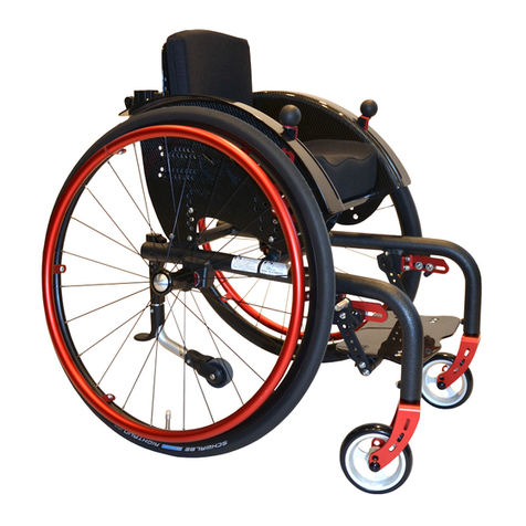
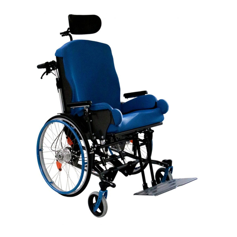
picture: Mio Move with taurus frame
1 PREAMBLE
1.1 GENERAL INFORMATION
�INDICATION
First and foremost, this service book is for the rehab tech-
nician.
All of the listed work is to be done by a qualied rehab
technician, due to safety reasons.
All of our wheelchairs fulll the guidelines and require-
ments according to 93/42/EWG, 2007/47/EWG and
EN12183:2009. SORG Rollstuhltechnik is also certied ac-
cording to the quality management system ISO 9001. With
this, the quality of our wheelchairs are guaranteed and doc-
umented in each step from development to assembling.
If you have any questions, our qualied team would be hap-
py to help you (+49 7254 9279-0).
1.2 SIGN EXPLANATION
ATTENTION
This is how individual related safety aspects of utmost im-
portance are indicated.
�INDICATION
This is how possible indications of utmost importance are
labeled.
INFORMATION
This is how INFORMATION on mounting and adjustment
work is labeled.
READ
This refers to additional material.
BOLD PRINT
Text in bold print highlights important passages or remarks.
1.3 RECEPTION
DELIVERY
Each wheelchair is mounted, tested for functionality and
correctness in our works and packaged into special card-
board boxes by our shipping experts.
FORWARDING COMPANY
RECEIVING
�INDICATION
For liability reasons we have to ask you to check the
1. frame
2. seat plate
3. seat cushion
4. wheel lock user lever
5. wheel cover
6. side guard
7. back cushion
8. height adjustable push bail
9. release lever for seat tilting
10. angle adjustment for push bail
11. foot plate
12. connection tube for leg
support
13. caster fork
14. caster
15. pressing bolt for wheel
lock
16. driving wheel
17. quick release axle
18. hand rim
1. push bail
2. release lever for seat tilting
3. angle adjustment for push bail
4. height adjustable tube for push bail
5. curved back plate
6. eccentric clamp for push bail
7. release lever for back angle adjustment
8. anti-tipper

service record
5
wheelchair IMMEDIATELY after receiving it and IN THE
PRESENCE of the deliverer (forwarding company) for
possible damages that may have occurred during trans-
portation.
CONFIRMATION OF RECEIPT
�INDICATION
Only sign the conrmation receipt after you have thor-
oughly checked the wheelchair for defects.
�INDICATION
In case of damages, note on the conrmation receipt
that you have received a damaged wheelchair.
TRANSPORTATION DAMAGES
In case of damages, please proceed as follows:
• write a short record of the damage and review of
events, if possible include pictures clearly show-
ing the damage,
• get the personal information of the bearer (driver’s
license etc.),
• inform us immediately.
�INDICATION
According to the valid law, damages reported late can
neither be asserted to us nor to the forwarding company.
1.4 SERVICE AND MAINTENANCE
READ
According to § 33 subparagraph 1, clause 4, [German]
SGB V, the responsibility of maintenance, repairs and
replacement lies with the benefactor. After agreement
with your benefactor, be sure to have all safety relevant
inspections, maintenance work and if necessary repairs
conducted in order to make the wheelchair functional.
ATTENTION
Only original parts are to be used for all service and main-
tenance work.
INFORMATION
Proceed according to the maintenance plan in the user man-
ual.
1.5 DOCUMENTATION
�INDICATION
Keep this service record in a safe place. Have all work/re-
pairs done on your wheelchair documented by the medical
supply store in the maintenance plan. If applicable, hand
it back to your benefactor along with the wheelchair.
�INDICATION
In the event of the wheelchair being reused, the service
book is an important source of information for you bene-
factor. It provides evidence of regular inspections which
might be relevant in the event of warranty claim.
1.6 ACCESSORY AND ATTACHMENT DRIVES
ATTENTION
The addition of these accessory and attachment drives is
done by either the manufacturer or the sanitary house and
solely in their responsibility.
1.7 ADJUSTMENTS ON THE WHEELCHAIR
ATTENTION: DANGER OF BRUISING
When operating the adjustable parts (back rest, side
guard, leg support, wheel lock, positioning aids etc.) as
well as xation and reparation work, there is an injury risk
or of crushing body parts in the pivoting range.
ATTENTION
All wheelchairs are to be handled with care. Removable
parts are not to be thrown or dropped!
ATTENTION
Before repairs or adjustments are made, clean/disinfect
the wheelchair and secure it from tipping over and/or fall-
ing down.
ATTENTION
Only use original spare parts.
ATTENTION
Safety nuts are only to be used once. After rst removal
the safety nut must be replaced by a new one.
1.8 TIGHTENING TORQUE AND TOOLS
INFORMATION
Technical changes reserved.
Screws
• M5: 5 Nm;
• M6: 7 Nm;
• M6: (axle plate) 10 Nm,
• M8: 20 Nm;
• M10 (Nut): 25Nm (caster)
• Fitting of quick-release axle: 35Nm
Tools needed:
• torque wrench (5-50 Nm)
• open end wrench
• ex ratchet handle with socket wrench inserts
• hexagon screwdriver
• Phillips screwdriver
• at head screwdriver
• plastic mallet
• side cutter
• threadlocker (uid)
• bicycle inner tube repair kit
• work bench/jaw vise with rubber pads
1.9 WORD EXPLANATION
Loosen screw:
means to only loosen the screw so that the parts are still
held together but (e.g.) can be moved around along a slot-
ted hole.
Remove screw:
means to completely remove the screw from where it was
attached so that the parts are no longer connected.
Mio Move
6
2 ADJUSTMENTS ON THE WHEELCHAIR
2.1 ASSEMBLY GROUP WHEELS
2.1.1 Centre of gravity/ active level/seat
height
The centre of gravity (active level), the seat height and the
seat angle of the wheelchair are normally set with the con-
stellation of rear wheels and casters or perforated plate on
wheelchairs of the production group 18.50.03. The wheel-
base of Mio, Kika II and Mio Move is xed and cannot be
changed. The centre of gravity is adjusted by the seat or
seat angle (see the appropriate chapter seat).
2.1.2 Camber
(1) In order to change the camber remove the rear wheels
and secure the wheelchair from rolling away.
• Completely remove the quick-release axle tting
(A) including the drum brake arm (B),
• place the camber adjustment (C) on the rear
wheel reception (D) (possible changes of camber
about ± 2°to 7°or 11° from horizontally turning
the camber adjustment 180°),
• replace quick-release axle tting (A) including the
drum brake arm (B), screw on tightly and
• put wheels back on.
(2) Check the distance of the rear wheel to the side guard by
shortly placing the rear wheel on.
(3) Correct the quick-release axle tting and turn it as far in
or out, that the wheels tire has a minimum distance of 10
mm to the side guard or the skirt guard.
• Loosen nuts (A) and (B),
• turn the quick-release axle adapter (C) in or out,
• retighten the nuts (A) and (B) (tightening torque
nuts M18 tting 35 Nm).
ATTENTION
After adjusting the quick-release axle adapter, be sure to
check that the wheel lock functions properly.
ATTENTION
Make sure the distance of the quick-release tting is the
same on the left and right!
2.1.3 Casters
The casters are tightly attached to the frame pipe and can-
not be adjusted.

(4) To displace/replace the casters:
• remove the screws (A) completely,
• remove the husks,
• change the casters,
• if necessary, guide the husks and wheels in the
new holes (B),
• replace the safety nuts with new ones (!)
• and retighten all the screws.
(B)
(C)
(A)
(B)
(1)
(B)
(B)
(A)
(A)
(4)
(2)
min. 10 mm
min. 10 mm
(B)
(C)
(A)
(3)

service record
7
2.2 ASSEMBLY GROUP SEAT
2.2.1 Tilting
You do not need to make any adjustments on the tilting
mechanism of the Mio Move.
(1) A list of names of the individual assembly parts of the
seat (the same parts are found mirror-inverted on the op-
posite side):
• (A) frame pipe
• (B) tilting
• (C) tilting slide
• (D) release mechanism for locking bolt
• (E) locking bolt for the tilting
• (F) cap nut with screw heads
2.2.2 Changing the seat position
(2+3) horizontal displacement
With a centered positioned seat you can change the seat
position along the tilting bar (A) 4,5 cm forward or 4,5 cm
backward.
• Secure the wheelchair from rolling away,
• loosen the four cap nuts (B) under the seat on the
inner surface (they do not have to be xated during
the process),
• turn the cap nuts (B) only so far that the screw
connection is retained (about half a turn),
• shift the seat along the tilting bar (A) in the desired
position and
• retighten all four cap nuts (B).
(4) vertical displacement
The vertical displacement by Mio Move takes place over the
thickness of the seat cushion and/or over the attachment of
spacer bushings between seat board (A) and the seat hold-
ers (B).
• (5) Remove the twelve screws (C),
• replace the screws (C) with twelve longer ones,
• place the spacer bushings between the seat board
(4A) and the seat holders (4B),
• place the new (longer) screws (C) back in the holes
• and tighten all of the screws (C).
(C)
(2)
(B)(A)
(5)
(3)
(B) (A)
(4)
(A)
(B)
(B)
(B)
(A)
(D)
(E)
(F)
(F)
(C)
(C)
(1)

Mio Move
8
2.2.3 Changing the seat width
The seat width is changed 2 cm through spacers between
frame and side guards.
• For preparation, remove the driving wheels, the
push bail, the stabilizing rod and back depression.
• (1) Remove the side guards on both sides with the
six screws (A).
• (2) Remove the seat board with the twelve screws
(A).
• (3+4) This way, you also remove the seat holders
(A).
• Displace the seat holders (A) under the seat board
in the alternative holes (B) of the seat board, place
the rest of the screws of the seat board also in the
alternative holes and
• screw them on to the tilting slide (C).
• Now screw on the new back in the areas provided
(see chapter “back”).
• (5) Place the spacers (A) between the side guard
holding xture (B) of the frame and the side guards,
• replace the six old screws with the new longer
ones and tighten them.
ATTENTION
Correct the quick release axle ttings and turn it so far
in/out so that the tire of the wheel has the least distance
at its vertex, however at least 10 mm, from the side guard
or skirt guard (see chapter “wheels”).
Be sure that the quick release axle ttings left and right,
have the same distance to the frame! Uneven distances
can lead to the wheelchair not driving straight.
(5)
(A)
(B)
(A)
(1)
(2)
(3)
(A)
(A) (C)
(4)
(B)
(B)

service record
9
2.2.4 Changing the seat depth
(1) To extend the seat board (A) with the seat extension (B):
• Loosen the four screws (C),
• pull the seat extension (B) as far forward as needed
• and retighten the screws (C).
2.2.5 Blocking the tilting
(2) Changing the maximum tilt
The measurement of the maximum tilting forward and/or
backward can (also afterwards) be reduced by adding so
called tilting blockers (B) on to the front and/or back of the
tilting slide (A).
With this, you ensure that you can only tilt forward to a
maximum of 0° and backward only to a maximum of
+15°,+20°,+25° or +30°.
To change/set the tilting blockage, secure the wheelchair
from rolling away and remove the driving wheels.
• (3) Turn the wheelchair upside down so that it is
easier to work on the bottom.
• If necessary, you must tilt the seat to reach the
“zero degrees position” (see picture 2) easier.
• Remove, if necessary, all four screws (A) on each
side,
• (4) displace the tilting blocker(s) (A) in the position
wanted (measurements see picture 2),
• place the lock screws (B) in the tilting blockers
from the outside
• and tighten these with the cap nuts (3A).
ATTENTION
Be sure that the blockers are attached the same on both
sides.
(2)
(3)
(4)
(A)
(B)
(A) (A)
maximal 0° +15° +20° +25° +30°
(A) (B)
(A)
(B)
(1)
(C)

Mio Move
10
(A)
(E1)
(E2)
(F2)
(F1)
(F3)
(F4)
(F5)
(B)
(C)
(A)
(C)
(D) (B)
(A)
(D)
(B)
(1)
(2)
(3)
2.3 ASSEMBLY GROUP BACK
The slot (A) of the back pipes (B) is screwed on to the seat
holder (C) with the screw (D). Picture (1) shows a back pipe
at the lowest position. The back pipes can be extended 50
mm.
2.3.1 Changing the back height
(1) To extend the back height 50 mm:
• Remove the screws on both sides (E1+2),
• move the back pipes up,
• move the screw (E1) in the hole (F1) and the screw
(E2) in the hole (F3).
• Retighten all screws.
ATTENTION
Should the safety nut of the screw connection (D) be
loose, even though it was glued, then it must be switched
with a new one and glued immediately. THE WHEELCHAIR
IS OTHERWISE NOT OPERABLE.
2.3.2 Replacing/removing the curved back pla-
te
(2) When widening the seat, rst you must remove the old
curved back plate (A).
• Remove the four screws (B),
• Widen the wheelchair as described,
• screw on the new curved back plate (A) with the
screws (B).
2.3.3 Bracket tabs for the curved back plate
If you use the curved back plate as a basis for a back shell
that you yourself upholster on the back plate, you can then
after only screw on the curved back plate on to the back
pipes from the back. For this you will need the bracket tabs,
which you must mount BEFORE you put the upholstery on.
(3) In order to mount the bracket tabs (B):
• Remove the curved back plate completely,
• place, as shown in the detailed drawing, the four
carriage bolts (A) from the front in to the shown
holes,
• place from the back the felt and bracket tabs (B)
on
• and put the cylinder head bolts (C) on, but WITH-
OUT TIGHTENING THEM.
• Mold your back shell.
• Then, put the curved back plate from the top over
the back pipes.
• Put the hexagon screw (D) on both sides in the
wanted holes of the back pipe and tighten these
screws (D).
• Afterwards, tighten the cylinder head bolts (C) of
the bracket tabs (B).

service record
11
(D)
(C)
(A)
(B)
(A)
(B)
(A)
(C)
(D)
(B)
(A)
(C)
(B)
(2)
(3)
(4)
2.4 ATTACHMENT FOR BELT SYSTEMS
2.4.1 Displacing the bottom metal locks
• (1+2) Open the metal locks (A) and remove the
belts,
• remove both screws (B) at the bottom of the belt
holder,
• displace the metal locks (A) in the wanted holes
(C)
• and replace the screws in the metal locks.
• Tighten the screws,
• guide the belts back in
• and close the metal locks.
2.4.2 Displacing the top metal locks
• (3) Open the metal locks (A) and remove the belts,
• loosen both screws of the metal locks at the bot-
tom of the belt holder,
• displace the metal locks (A) along the elongated
holes (B) in to the position wanted
• and retighten the screws.
• Guide the belts back in and close the metal locks.
2.4.3 Height setting of the belt holders
(4) You can displace the height of the top belt holder (A)
along the prole tube (B) (e.g. if you need the top tube end
to attach a headrest).
• Open the screws (C) on the clamping prole (D),
• put the belt holder (A) in the position wanted
• and retighten the screws (C).
ATTENTION
Please make sure that the belts do not touch the neck of
the child/user—INGURY RISK!
Guide the top belt as far away from the neck of the child/
user as possible.
This is why you need to adjust the height of the top belt
holder only with the child/user in the wheelchair.
(1)

Mio Move
12
2.5. ASSEMBLY GROUP PUSH AIDS
2.5.1 Height adjustable push bail
(1) At the bottom end of the height adjustable push bail
tubes (A) there are tripod springs (B) with which an unwanted
sliding out of the holders (C) by the tubes is prevented.
ATTENTION
The push bail (A) can only be used if the tripod springs (B)
are visible under the holder (C). A non functioning tripod
spring must be replaced immediately.
2.5.2 Clamping force of the eccentric clamp
ATTENTION
(2) The clamp lever (A) of the eccentric clamp is xated
with a nut on the opposite side of the holder (B). When
turning the clamp lever (A) the clamping force of the
eccentric clamps changes. The nut may get lost under
adverse circumstances. THE PUSH AID IS THEN NOT
FUNCTIONABLE.
This is why you must make sure that the user checks
the functionality and the completeness of the eccentric
clamp regularly and in short intervals.
In order to set the locking force of the eccentric clamp:
• Open the clamp lever (A),
• turn it so far on its own axis that it reliably xates
the push bail;
• clockwise= tighten,
• counterclockwise= loosen.
Afterwards test its functionality.
ATTENTION
(3) The curve of the saddle washer (A) must be concise
with the curve of the clamp lever with a closed eccentric
clamp (B).
2.5.3 Foldable one-hand push bail
ATTENTION
(4) Make sure, that the user checks the functionality of
the complete angle adjustment element (A) on the push
bail or on the foldable push bail regularly and in short
intervals.
In order to set the clamping force of the eccentric clamp,
please proceed as described above.
(1)
(B)
(A)
(C)
(B)
(A)
(A)
(2)
(4)
(A)
(B)
(3)

service record
13
2.6 ASSEMBLY GROUP LEG SUPPORTS
ATTENTION
A too highly set foot plate can lead to a kink stance in the
pelvis and a too low set foot plate can lead to jams in the
thighs.
The thighs must lie evenly on the seat cushion; the back
of the knees must stay free.
2.6.1 Leg support standard
The mounting of the leg support takes place in the middle
under the seat plate.
(1) Setting the lower leg length:
• Loosen both screws on both sides (A+B),
• push both foot plate holders (clamping prole) (C)
in the position wanted,
• retighten the screws (B),
• but only tighten the screws (A) so tight that the
foot plate can still be folded back.
(2) Setting the depth:
• Loosen all four screws (A) under the seat plate,
• slide the leg support holder (B) in the position
wanted
• and retighten the screws (A).
Setting the angle:
(3) The angle of the foot plate is set by us at 90° ex works.
(4) By changing the end stop (A) on the tubes (B) the angle
of the foot plate can be adjusted up to ± 15°.
(5) For this, the position of the foot plate (B) must be moved
forward (= slanting foot plate) or backward (= rising foot
plate) on the holder unit (C).
• Loosen all four screws (D),
• put the foot plate in the position wanted
• and retighten the screws.
(A)
(B)
(C)
(1)
(A)
(2)
(B)
(3)
90°
(A)
(B)
(B)
(4)
(B)
(C)
(5)
(A)
(D)
(A)

Mio Move
14
2.6.2 Foot plate can be elevated, divided
(1) In order to elevate the leg support:
• Secure the wheelchair from rolling away by
tightening the wheel lock and activate the an-
ti-tipper.
• Loosen the clamp lever (A) on both sides,
• put the leg support/s in the position wanted
• and retighten the clamp lever/s (A).
(2) To balance to length:
• Loosen the clamp lever/s (B) on both sides,
• pull the bottom end (C) of the leg support/s to the
wanted length
• and retighten the clamp lever/s (B).
2.6.3 Leg rest
(3+4) Setting the position:
• Loosen the clamp lever (A) underneath the cush-
ion (B) (see picture 4),
• place the cushion (B) in the position wanted
• and retighten the clamp lever (A).
Setting the tilting angle:
• Loosen the screws (C) of the cushion holder on
both sides inside and outside,
• place the cushion (B) in the position wanted
• and retighten the screws (C).
(2)
(B)
(C)
(D)
(B)
(A)
(1)
(A)
(C)
(B)
(4)
(A)
(B)
(3)

service record
15
2.7 ASSEMBLY GROUP SIDE GUARDS
The side guards on the Mio Move cannot be changed.

Adjusting the skirt guard
(1) The skirt guard (A) can be adjusted in height:
• Loosen the screws (B) on both sides,
• set the height of the skirt guard (A)
• and retighten the screws (B).

(1) If necessary, the length of the brake lever (C) needs to be
adjusted to the new position of the skirt guard:
• Loosen the screws (D) on both sides,
• align the brake lever (C)
• and retighten all of the screws (D).
INFORMATION
Afterwards, be sure to check the functionality of the
brake!
ATTENTION DANGER OF BRUISING FINGERS
(2) Keep the distance between skirt guard and tire as
small as possible. The child should not be able to put its
ngers in between.
(2)
(A)
(C) (D)
(B)
(1)

Mio Move
16
(A)
(B)
(2)
(A)
(B)
(C)
(D)
(3)
(1)
(A)
(A)
(B)
(C)
(C)
2.8 ASSEMBLY GROUP BRAKES
2.8.1 Wheel lock/service brake
ATTENTION
WHEEL LOCKS ONLY SERVE THE PURPOSE OF PUTTING
THE WHEELS IN A RESTING POSITION. THEY ARE NOT
MADE TO BRAKE THE WHEELCHAIR WHILE DRIVING.
ATTENTION
BE SURE TO CHECK THE FUNCTIONALITY OF THE BRAKES
AFTER EVERY ADJUSTMENT ON THE DRIVING WHEELS.
The wheelchair with passenger (max. load capacity) must
stand securely, with drawn brake, on a ramp with a 12,3%
(= 7°) decent.
INFORMATION
The maximum distance between the brake pressing bolt
and the tires, with opened brake, is as follows:
Standard KLB 21mm
Pull to lock brake 11mm
KLB with rollback blocking about 10mm
cable brake 6mm
(technical changes reserved).
2.8.2 Cable brake
(1) The wheel lock consists of:
• (A) brake pressing bolt,
• (B) brake lever (if applicable with extension),
• (C) adjustment screws.
(2) To retention the cable control
• loosen the locking nut (A)
• and turn the setting screw (B):
• clockwise = tighten,
• counterclockwise = loosen.
• Afterwards, retighten the locking nut (A).
(2) In order to change the distance between the brake
pressing bolt (C) and the driving wheel:
• Loosen both screws (D),
• move the whole brake pad ,while the brake is
open, in the new position
• and retighten the screws (D).
ATTENTION
AFTERWARDS, CHECK THE FUNCTIONALITY OF THE
BRAKE.
2.8.3 Setting the length of the brake lever
(3) In order to set the length of the brake lever:
• Loosen both screws (A), if necessary, on both
sides,
• align the brake lever (B)
• and retighten all the screws (A).
ATTENTION
AFTERWARDS, CHECK THE FUNCTIONALITY OF THE
BRAKE.

service record
17
2.8.4 Drum brake
The brake force of the drum brake is set ideally by our
mechanics.
ATTENTION
For safety reasons it is necessary to regularly check the
functionality, since through permanent use an adjustment
of the brake force or even a replacement of a Bowden
cable can be essential.
(1+3) The following parts of the drum brake are crucial for
adjusting the brake force:
• setting screw (A)
• locking nut (B)
• push-on nipple (C)
• holder (D)
• holder screw (E)
• inner cable (F)
• locking lever (G)
• clamp (H)
• brake shoe (I)
(3) To Install the Bowden cable:
• Place the push-on nipple (C) with the setting screw
(A) and the locking nut (B) at the bottom end in the
holder (D),
• guide the inner cable (F) through the clamp (H),
• place the clamp (H) in the locking lever (G) and
• push the locking lever (G) slightly forward toward
push-on nipple (C), so that a slight pull between
clamp and push-on nipple occurs.
• Tighten the clamp (H).
• Put the wheel back on and check if the brake
shoes (I) already grind against the brake pad.
• For this, jack up the wheelchair or tilt it to the side.
The wheel must be able to turn unhindered.
• Should the brake shoes (I) grind (without using the
control lever), loosen the clamp (H) and
• give the locking lever (G) more room.
• After, retighten the clamp (H).
To set the brake force:
• remove the locking nut (B) on the setting screw (A),
• tighten or loosen the inner cable (F) by turning the
setting screw (A),
• test the traction on the control lever and
• retighten the locking nut (B).
� INDICATION
Possible impairments of the brake force can occur from:
• wrongfully adjusted traction of the Bowden
cables,
• defected Bowden cable,
• dirty brake pads/brake shoes.
ATTENTION
The wheelchair with passenger (max. load capacity) must
stand securely, with drawn brake, on a ramp with a 12,3%
(= 7°) decent.
(A)
(D)(E)
(D)(E)
(D)
(B)(C)
(F) (G) (I)(H)
(A)(B)(C)
(F)
(G)(H)
(I)
(1)
(2)

Mio Move
18
2.9 ASSEMBLY GROUP ANTI-TIPPER
(1) The anti-tipper consists of 4 parts: Anti-tipper holder (A),
foot lever (B), anti-tipper wheel (C) with holder and the an-
ti-tipper bail (D) which can be pulled down and turned 180°
(partly sticking in the anti-tipper holder).
(2) The height of the anti-tipper can be changed by the
screw (A):
• Remove the driving wheels,
• remove the screws (A) and the case (B),
• displace the anti-tipper bail (C) in the holder (D) in
the position wanted (E),
• replace the case (B) and the screw (A)
• and retighten the screw.
ATTENTION
The bottom hole (F) is design related and cannot be used.
The anti-tipper bail could slide out of the holder when
turning/activating the anti-tipper.
(3) If the wheelchair if set very active and the activated an-
ti-tipper sticks out too far back, then the anti-tipper bail can
be shortened.
• Remove the screw (B)
• remove the anti-tipper wheel and the holder (A),
• shorten the anti-tipper bail (C) with a saw to the
length wanted,
• place the anti-tipper wheel and the holder back on
the anti-tipper bail (C),
• place the screws (B) in the hole (D)
• and tighten the screw (B).
(A)
(B)
(E)
(F)
(C)(D)
(A)
(A) (B) (C)(D)
(C)
(B)
(D)
(D)
(1)
(2)
(3)

service record
19
2.10 ASSEMBLY GROUP TRUSS PADS
2.10.1 Classification
(1) The truss pads consist of the following parts:
• (A) locking joint
• (B) connection (C-bar)
• (C) truss pad cushion
• (D) truss pad holder
2.10.2 Vertical setting
(2) The vertical setting of the truss pads occurs on the one
hand by moving the locking joint (A) along the c-bar (B):
• Loosen both screws (C),
• move the locking joint (A),
• and retighten the screws (C).
(3) The locking joint (A) is, through the connection with
the metal tongue (B), jammed into the c-bar (D) with both
screws (C).
(3) On the other hand, the truss pads can be adjusted by
moving the c-bar (D) along the back tube holder:
• Loosen, if necessary, both screws (B) and slide the
truss pad holder (A) out of the c-bar (D).
• Remove the screws (E)
• and displace the c-bar (D) along the alternative
holes (F),
• replace the screws (E)
• and retighten them.
• Then, slide the truss pad holder (A) in the c-bar
(D),
• place it to the height wanted
• and retighten the screws (B).
(4) Additionally, with truss pad size II the height can be ad-
justed be displacing the cushions:
• Remove the cover,
• remove both screws (A),
• displace the cushion (B) in the alternative holes
(C),
• replace both screws (A)
• and retighten them.
• After, replace the covers.
(2)
(3)
(A)
(B)
(C)
(4)
(B)
(B)
(C)
(A)
(A)
(E)
(F)
(B)
(1)
(C)(D)
(A)
(C)
(D)
(E)

Mio Move
20
(5a)
(5b)
(A)
(B)
(6)
(A)
(A)
(B)
(B)
(A)
(8)
(7) (A)
2.10.3 Horizontal setting
(5a+b) The horizontal setting occurs on the one hand by dis-
placing the locking joint.
• Remove both screws (A),
• place the locking joint in the alternative holes (B),
• place the screws (A) in the metal tongue (picture
3C, last page),
• set the height
• retighten the screws (A).
(6) On the other hand, it can occur by displacing the cush-
ions:
• Remove the covers,
• loosen the screws (A),
• displace the cushion
• and retighten the screws (A).
• After, replace the covers.
Horizontal extension
(7) For the horizontal extension add a extension piece (spare
part):
• Remove the screws (A),
• add the extension piece
• and screw it together on both ends.
2.10.4 Fine adjustment of the truss pad holder
(8) The ne adjustment of the room between locking joint
and truss pad holder occurs with the adjustment screw (A).
• Close the locking joint
• and turn the adjustment screw (A) from the out-
side in the necessary measure open or closed.
2.10.5 Adjusting to the user
If all positioning and extension works are nished:
• Place the truss pads around the user,
• adjust the joints in the necessary position
• and tighten all joint screws (7A).
• The ball joint is then xated by tighten the four
screws (6B).
Other manuals for MIO MOVE
2
Table of contents
Other SORG Wheelchair manuals

SORG
SORG Airon Service manual

SORG
SORG Jump alpha User manual

SORG
SORG Jump alpha Service manual

SORG
SORG Loop RS Service manual

SORG
SORG Mio User manual

SORG
SORG Jump beta User manual

SORG
SORG MIO MOVE Service manual

SORG
SORG Dynamis MV Service manual

SORG
SORG Siro II User manual

SORG
SORG Mio Carbon Design 2018 User manual
Popular Wheelchair manuals by other brands

Pride Mobility
Pride Mobility JAZZY 1103 owner's manual

Ki Mobility
Ki Mobility LIBERTY FT User instruction manual & warranty

Magic Mobility
Magic Mobility Extreme X8 with G90 owner's manual

Vermeiren
Vermeiren Eclips XXL user manual

Otto Bock
Otto Bock Minny Instructions for use

Invacare
Invacare 2GT parts catalog