SORG MIO MOVE Service manual

Service Record Mio Move 1 of 32
2019-07-16
Mio Move
Unique people, unique solutions.
Service Record Mio Move
ENG
Service Record
In the following all individual adjustments of the wheelchair are
described. These adjustments require tools and specialised
knowledge. Please leave the adjustments to a qualied rehab
consultant.

2 of 32 Service Record Mio Move 2019-07-16
Imprint
SORG Rollstuhltechnik GmbH+Co.KG
Benzstraße 3-5
68794 Oberhausen-Rheinhausen / Germany
Tel. +49 7254-9279-0
Fax +49 7254-9279-10
E-Mail [email protected]
Web www.sorgrollstuhltechnik.de
Revision status
2019-07-12
Technical status
Technical changes and misprints reserved. The
pictures in this Instructions for use can dier
from the actual equipment components. How-
ever, a corresponding conduction is possible.
Copyright
All texts, pictures and graphics underlie co-
pyright protection. All rights, including co-
pying, publishing, editing and translating,
remain reserved. © by SORG Rollstuhltech-
nik GmbH+Co. KG Benzstraße 3-5, 68794
Oberhausen-Rheinhausen / Germany.
Our terms and conditions can be found
on our order forms and at www.sorgrollstuhl-
technik.de/impressum.

Service Record Mio Move 3 of 32
2019-07-16
Table of content
1 Wheelchair overview 4
2 General information 5
2.1 General indications 5
2.2 Documentation indications 5
2.3 Required torques and tools 5
2.4 Explanation of symbols 6
2.5 General safety instructions 7
3 Assembly groups 8
3.1 Assembly group wheels 8
3.1.1 Centre of gravity/ wheelbase 8
3.1.2 Camber 8
3.1.3 Casters 9
3.2 Assembly group seat 10
3.2.1 Tilting 10
3.2.2 Changing the seat position 10
3.2.3 Changing the seat width 11
3.2.4 Blocking the tilting 11
3.3 Assembly group back 12
3.3.1 Changing the back height 12
3.3.2 Replacing the curved back plate 12
3.3.3
Bracklet tabs for the curved back plate
13
3.3.4 Adjust back cover 13
3.4 Assembly group belt system 14
3.4.1 Displacing the bottom metal locks 14
3.4.2 Displacing the top metal locks 14
3.4.3 Height setting of the belt holders 15
3.5 Assembly group leg support 16
3.5.1 Leg support standard 16
3.5.2 Foot plate can be elevated, divided 17
3.5.3 Leg rest 17
3.6 Assembly group side guards 18
3.6.1 Side guards 18
3.7 Assembly group brake 19
3.7.1 Wheel lock 19
3.7.2 Cable brake 19
3.7.3
Setting the length of the brake lever
20
3.7.4 Drum brake 20
3.8 Assembly group anti-tipper 22
3.8.1 Adjust height 22
3.9 Assembly group truss pads 23
3.9.1 Classication 23
3.9.2 Vertical setting 23
3.9.3 Horizontal setting 24
3.10 Assembly group outdoor front end 25
3.10.1 Settings 25
4 Repairs and maintenance 27
4.1 Repairs 27
4.2 Spare parts 27
4.3 Maintenance 27
4.4 Disinfection 27
4.5 Storage 27
4.6 Reinstatement 28
4.7 Disposal 28
4.8 Maintenance/ Inspection 28
5 Technical specications 30
5.1 Data and measurements 30
5.2 Meaning of labels 31
5.3 Declaration of conformity 31

4 of 32 Service Record Mio Move 2019-07-16
1 Wheelchair overview
1push bail
2back cushion
3side guard
4wheel cover
5brake lever
6seat cushion
7seat plate
8frame
9leg support
10 caster fork
11 caster
12 brake block wheel lock
13 rear wheel
14 quick-release axle
15 hand rim
16 push bail
17 triggering lever tilt mechanism
18 angle adjustment
19 rm curved back plate
20
Eccentric tensioner for push bail
21 anti-tipper
8
16
7
17
6
18
5
4
19
3
20
2
21
1
9101112131415

Service Record Mio Move 5 of 32
2019-07-16
2 General information
2.1 General indications
In the following all individual settings, adjustments and repairs as well as the yearly inspection of
the wheelchair are described. These adjustments require tools and specialised knowledge. Ple-
ase leave the adjustments to a qualied rehab consultant.
Should questions or suggestions come up then please contact your medical supply store or our
team (+49 7254 9279-0).
2.2 Documentation indications
Please note:
• Information about before sale can be found in the instructions for use
• Infomation for the user can be found in the instructions for use
• For maintenance instructions see: Chapter 4 (Repair & Maintenance)
2.3 Required torques and tools
For the following screws needed torque:
• M5: 5 Nm;
• M6: 7 Nm;
• M6 (axle plate) 10 Nm
• M8: 20 Nm;
• M10 (nut): 25 Nm; (caster)
• quick release axle tting 40 Nm
Needed tools:
• torque wrench (5-50 Nm)
• open end wrench
• ex ratchet handle with socket wrench inserts
• hexagon screw driver
• Phillips screw driver
• at head screw driver
• plastic mallet
• side cutter
• threadlocker (uid)
• bicycle inner tube repair kit
• work bench/jaw vise with rubber pads

6 of 32 Service Record Mio Move 2019-07-16
2 General information
2.4 Explanation of symbols
ATTENTION! Warnings for perso-
nal Safety aspects that are of the
utmost importance.
CORRECT safety adjustment/ use
WRONG adjustment/ use
NOT ALLOWED
References to additional/conti-
nuing reading.
Setting or adjusting the angle
open/ close
Turn clockwise
Turn counter-clockwise
steps to be done at the same
time
steps to be done after each other
steps to be done on both sides
Use
(A); (B)
1. 1.
1. 2.
;
2x
push/ pull/ insert / move/
Push in specic direction
important detail
correct or proper use/setting
incorrect or improper use/setting
reference from text to detail
point of view
view from top
view from the side
view from the bottom
view from the front
view from the back
fasten parts
remove parts

Service Record Mio Move 7 of 32
2019-07-16
2 General information
2.5 General safety instructions
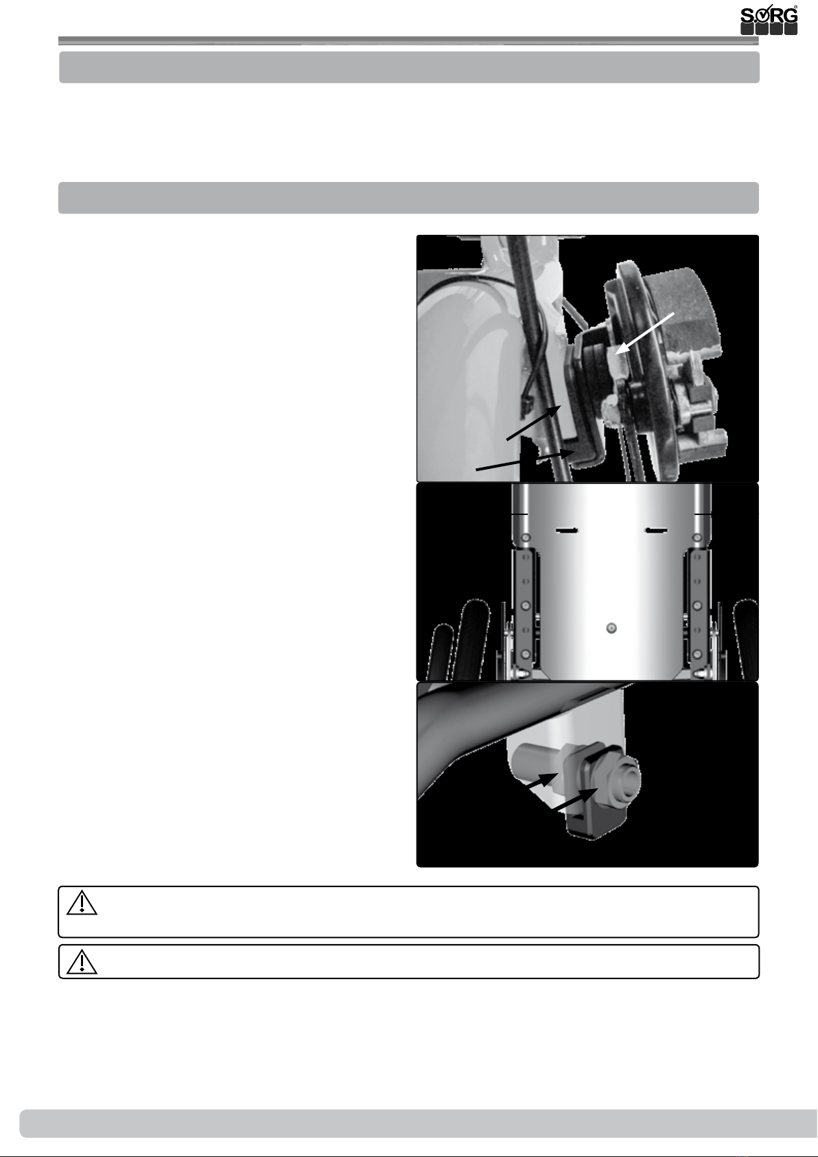
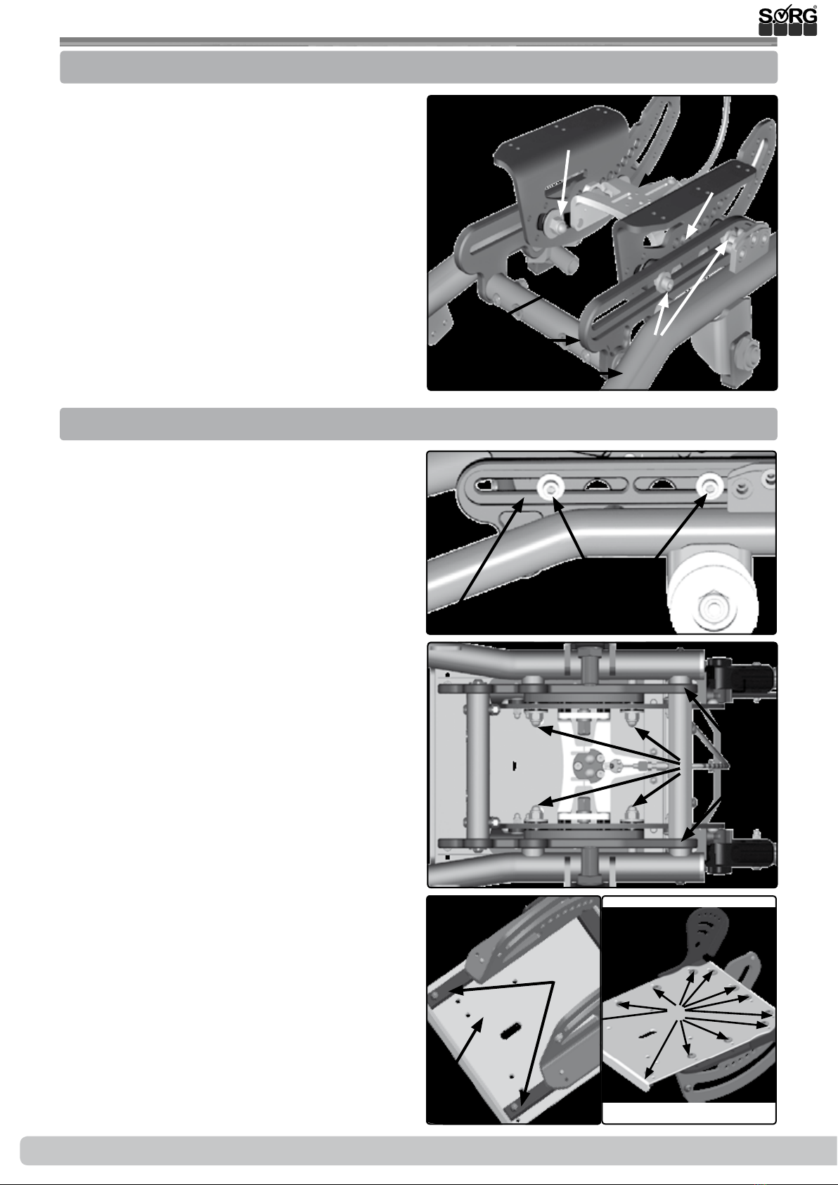
Before each use be sure to check:
• frame, back tubes, attachments and accessories for visible damage, bends, cracks or mis-
sing/loose scews,
• wheels/quick release axles for rm t,
• sucient tire pressure, tire tread,
• functionality of the brakes,
• rm t of the angle adjustment elements/ eccentric clamps,
• rm t of the seat plate/ the back/ the foot plate,
• functionality of the anti-tipper/ seat and back straps,
• if all previously disassembled parts are re-inserted or rmly locked.
There is a risk of injuries (e. g. such as bruising) on all rotating or folding parts, including
adjustments, repairs and transport.
All wheelchair parts are to be handled with care. Do not throw or drop removable parts.
Before repairs or adjustments are made, clean/didinfect the wheelchair and secure it from
tipping over and/or falling down.
Only use original spare parts.
Safety nuts may only be used once. Lossened safety nuts must be replaced by new ones.
Only the regular maintenance of all safety-relevant parts on the wheelchair by a qualied
rehab workshop protects against damage and maintains our manufacturer's warranty.
Combination with products from other manufacturers
The wheelchair may only be combined with the electrical auxiliary drives apporved by the
manufacturer. Restrictions or adaptations as well as the attachment itself must be done by the
supplier of the additional system or the authorized specialist dealer.
Please check the conditions with the manufacturerer of the audiliary drives.
In combination of wheelchair and electric auxiliary drive, certain strains can occur which
can lead to damage to the wheelchair. Slowly approach obstacles and carefully overcome
them so that little force is applied to the caster, driving wheel and wheelchair as a whole.

8 of 32 Service Record Mio Move 2019-07-16
3.1 Assembly group wheels
3.1.1 Centre of gravity/ wheelbase
The center of gravity (degree of activity), the seat height and the seat angle of the wheelchair
are used for wheelchairs of product group 18.50.03. usually set with the constellation drive and
steering wheels or the perforated plate. The wheelbase is xed on the Mio and can not be chan-
ged. The center of gravity is adjusted via the seat support angle.
3.1.2 Camber
Variant till 31.12.2016:
In order to change the camber remove the rear
wheels and secure the wheelchair from rolling
away.
• Completely remove the quick-release
axle tting (A) including the drum brake
arm (B),
• place the camber adjustment (C) on
the rear wheel reception (D) (possible
changes of camber about ± 2°to 7°or
11° from horizontally turning the camber
adjustment 180°),
• replace quick-release axle tting (A) in-
cluding the drum brake arm (B), screw
on tightly and
• put wheels back on.
(2) Check the distance of the rear wheel to the
side guard by shortly placing the rear wheel on.
(3) Correct the quick-release axle tting and
turn it as far in or out, that the wheels tire has a
minimum distance of 10 mm to the side guard
or the skirt guard.
• Loosen nuts (A) and (B),
• turn the quick-release axle adapter (C) in
or out,
• retighten the nuts (A) and (B) (tighten-
ing torque nuts M18 tting 35 Nm).
After adjusting the quick-release axle adapter, be sure to check that the wheel lock functions
properly.
Make sure the distance of the quick-release tting is the same on the left and right!
The camber and toe adjustment from 01.01.2017 can be found in our service brochure Camber
and toe compensation. This can be found at http://www.sorgrollstuhltechnik.de/
(B)
(C)
(A)
(B)
(1)
(2)
min. 10 mm
min. 10 mm
(B)
(C)
(A)
(3)

Service Record Mio Move 9 of 32
2019-07-16
3.1 Assembly group wheels
3.1.3 Casters
The casters are tightly attached to the frame
pipe and cannot be adjusted.
(1) To displace/replace the casters:
• remove the screws (A) completely,
• remove the husks,
• change the casters,
• if necessary, guide the husks and wheels
in the new holes (B),
• replace the safety nuts with new ones (!)
• and retighten all the screws. (B)
(A)
(1)
(B)
(A)

10 of 32 Service Record Mio Move 2019-07-16
3.2.1 Tilting
3.2 Assembly group seat
You do not need to make any adjustments on
the tilting mechanism of the Mio Move.
(1) A list of names of the individual assembly
parts of the seat (the same parts are found mir-
ror-inverted on the opposite side):
• (A) frame pipe
• (B) tilting
• (C) tilting slide
• (D) release mechanism for locking bolt
• (E) locking bolt for the tilting
• (F) cap nut with screw heads
(B)
(B)
(A)
(D)
(E)
(F)
(F)
(C)
(C)
(1)
3.2.2 Changing the seat position
(2+3) horizontal displacement
With a centered positioned seat you can change
the seat position along the tilting bar (A) 4,5 cm
forward or 4,5 cm backward.
• Secure the wheelchair from rolling away,
• loosen the four cap nuts (B) under the
seat on the inner surface (they do not
have to be xated during the process),
• turn the cap nuts (B) only so far that the
screw connection is retained (about half
a turn),
• shift the seat along the tilting bar (A) in
the desired position and
• retighten all four cap nuts (B).
(4) vertical displacement
The vertical displacement by Mio Move takes
place over the thickness of the seat cushion
and/or over the attachment of spacer bushings
between seat board (A) and the seat holders
(B).
• (5) Remove the twelve screws (C),
• replace the screws (C) with twelve longer
ones,
• place the spacer bushings between the
seat board (4A) and the seat holders
(4B),
• place the new (longer) screws (C) back
in the holes
• and tighten all of the screws (C).(C)
(2)
(B)(A)
(5)
(3)
(B) (A)
(4)
(A)
(B)

Service Record Mio Move 11 of 32
2019-07-16
3.2.3 Changing the seat width
3.2 Assembly group seat
(1) To extend the seat board (A) with the seat
extension (B):
• Loosen the four screws (C),
• pull the seat extension (B) as far forward
as needed
• and retighten the screws (C).
(A)
(B)
(1)
(C)
3.2.4 Blocking the tilting
(2) Changing the maximum tilt
The measurement of the maximum tilting
forward and/or backward can (also afterwards)
be reduced by adding so called tilting blockers
(B) on to the front and/or back of the tilting
slide (A).
With this, you ensure that you can only tilt
forward to a maximum of 0° and backward only
to a maximum of +15°,+20°,+25° or +30°.
To change/set the tilting blockage, secure the
wheelchair from rolling away and remove the
driving wheels.
• (3) Turn the wheelchair upside down so
that it is easier to work on the bottom.
• If necessary, you must tilt the seat to
reach the “zero degrees position” (see
picture 2) easier.
• Remove, if necessary, all four screws (A)
on each side,
• (4) displace the tilting blocker(s) (A) in
the position wanted (measurements see
picture 2),
• place the lock screws (B) in the tilting
blockers from the outside
• and tighten these with the cap nuts (3A).
Be sure that the blockers are attached
the same on both sides.
(2)
(3)
(4)
(A)
(B)
(A) (A)
maximal 0° +15° +20° +25° +30°
(A) (B)

12 of 32 Service Record Mio Move 2019-07-16
3.3.1 Changing the back height
3.3 Assembly group back
The slot (A) of the back pipes (B) is screwed
on to the seat holder (C) with the screw (D).
Picture (1) shows a back pipe at the lowest po-
sition. The back pipes can be extended 50 mm.
(A)
(E1)
(E2)
(F2)
(F1)
(F3)
(F4)
(F5)
(B)
(C)
(D)
(1)
(1) To extend the back height 50 mm:
• Remove the screws on both sides (E1+2),
• move the back pipes up,
• move the screw (E1) in the hole (F1) and the screw (E2) in the hole (F3).
• Retighten all screws.
Should the safety nut of the screw connection (D) be loose, even though it was glued, then
it must be switched with a new one and glued immediately. The wheelchair is otherwise not
operable.
3.3.2 Replacing/ removing the curved back plate
(2) When widening the seat, rst you must
remove the old curved back plate (A).
• Remove the four screws (B),
• Widen the wheelchair as described,
• screw on the new curved back plate (A)
with the screws (B).(A) (B)
(2)

Service Record Mio Move 13 of 32
2019-07-16
3.3.3 Bracklet tabs for the curved back plate
3.3 Assembly group back
If you use the curved back plate as a basis for
a back shell that you yourself upholster on the
back plate, you can then after only screw on the
curved back plate on to the back pipes from the
back. For this you will need the bracket tabs,
which you must mount before you put the up-
holstery on.
(1) In order to mount the bracket tabs (B):
• Remove the curved back plate complete-
ly,
• place, as shown in the detailed drawing,
the four carriage bolts (A) from the front
in to the shown holes,
• place from the back the felt and bracket
tabs (B) on
• and put the cylinder head bolts (C) on,
but without tightening them.
• Mold your back shell.
• Then, put the curved back plate from the
top over the back pipes.
• Put the hexagon screw (D) on both sides
in the wanted holes of the back pipe and
tighten these screws (D).
• Afterwards, tighten the cylinder head
bolts (C) of the bracket tabs (B).
(C)
(D) (B)
(A)
(1)
3.3.4 Adjust back cover
• (2) Open the velcro connections (A)
andbring the straps to the desired posi-
tion.
• Close the connections (A) again.
Velcro and velcro part must be min.
Overlap 8 cm.
A
A
A
A
min. 8 cm
(2)

14 of 32 Service Record Mio Move 2019-07-16
3.4.1 Displacing the bottom metal locks
3.4 Assembly group belt system
• (1+2) Open the metal locks (A) and
remove the belts,
• remove both screws (B) at the bottom of
the belt holder,
• displace the metal locks (A) in the want-
ed holes (C)
• and replace the screws in the metal locks.
• Tighten the screws,
• guide the belts back in
• and close the metal locks.
(D)
(C)
(A)
(B)
(A)
(C)
(B)
(2)
(1)
3.4.2 Displacing the top metal locks
• (3) Open the metal locks (A) and re-
move the belts,
• loosen both screws of the metal locks at
the bottom of the belt holder,
• displace the metal locks (A) along the
elongated holes (B) in to the position
wanted
• and retighten the screws.
• Guide the belts back in and close the
metal locks.
(A)
(B)
(3)

Service Record Mio Move 15 of 32
2019-07-16
3.4.3 Height setting of the belt holders
3.4 Assembly group belt system
(1) You can displace the height of the top belt
holder (A) along the prole tube (B) (e.g. if
you need the top tube end to attach a head-
rest).
• Open the screws (C) on the clamping
prole (D),
• put the belt holder (A) in the position
wanted
• and retighten the screws (C).(B)
(A)
(C)
(D)
(1)
Please make sure that the belts do not touch the neck of the child/user - Ingury Risk.
Guide the top belt as far away from the neck of the child/user as possible.
This is why you need to adjust the height of the top belt holder only with the child/user in the
wheelchair.

16 of 32 Service Record Mio Move 2019-07-16
3.5.1 Leg support standard
3.5 Assembly group leg support
A too highly set foot plate can lead to a kink stance in the pelvis and a too low set foot
plate can lead to jams in the thighs. The thighs must lie evenly on the seat cushion; the back
of the knees must stay free.
The mounting of the leg support takes place in
the middle under the seat plate.
(1) Setting the lower leg length:
• Loosen both screws on both sides (A+B),
• push both foot plate holders (clamping
prole) (C) in the position wanted,
• retighten the screws (B),
• but only tighten the screws (A) so tight
that the foot plate can still be folded
back.
(2) Setting the depth:
• Loosen all four screws (A) under the seat
plate,
• slide the leg support holder (B) in the
position wanted
• and retighten the screws (A).
Setting the angle:
(3) The angle of the foot plate is set by us at 90°
ex works.
(4) By changing the end stop (A) on the tubes
(B) the angle of the foot plate can be adjusted
up to ± 15°.
(5) For this, the position of the foot plate (B)
must be moved forward (= slanting foot plate)
or backward (= rising foot plate) on the holder
unit (C).
• Loosen all four screws (D),
• put the foot plate in the position wanted
• and retighten the screws.
(A)
(B) (C)
(1)
(A)
(2)
(B)
(3)
90°
(A)
(B)
(B)
(4)
(B)
(C)
(5)
(A)
(D)
(A)

Service Record Mio Move 17 of 32
2019-07-16
3.5 Assembly group leg support
3.5.2 Foot plate can be elevated, divided
(1) In order to elevate the leg support:
• Secure the wheelchair from rolling away
by tightening the wheel lock and acti-
vate the anti-tipper.
• Loosen the clamp lever (A) on both sides,
• put the leg support/s in the position
wanted
• and retighten the clamp lever/s (A).
(2) To balance to length:
• Loosen the clamp lever/s (B) on both
sides,
• pull the bottom end (C) of the leg sup-
port/s to the wanted length
• and retighten the clamp lever/s (B).
(2) (B)
(C)
(D)
(B)
(A)
(1)
3.5.3 Leg rest
(3+4) Setting the position:
• Loosen the clamp lever (A) underneath
the cushion (B) (see picture 4),
• place the cushion (B) in the position
wanted
• and retighten the clamp lever (A).
Setting the tilting angle:
• Loosen the screws (C) of the cushion
holder on both sides inside and outside,
• place the cushion (B) in the position
wanted
• and retighten the screws (C).
(A)
(C)
(B)
(4)
(A)
(B)
(3)

18 of 32 Service Record Mio Move 2019-07-16
3.6 Assembly group side guards
3.6.1 Side guards
The side guards on the Mio Move cannot be
changed.
Adjusting the skirt guard
(1) The skirt guard (A) can be adjusted in height:
• Loosen the screws (B) on both sides,
• set the height of the skirt guard (A)
• and retighten the screws (B).
(1) If necessary, the length of the brake lever
(C) needs to be adjusted to the new position of
the skirt guard:
• Loosen the screws (D) on both sides,
• align the brake lever (C)
• and retighten all of the screws (D).
Afterwards, be sure to check the functionality
of the brake!
(2) Keep the distance between skirt guard
and tire as small as possible. The child should
not be able to put its ngers in between.
(2)
(A)
(C) (D)
(B)
(1)

Service Record Mio Move 19 of 32
2019-07-16
3.7.1 Wheel lock
3.7 Assembly group brake
Wheel locks only serve the purpose of putting the wheels in a resting position. They are
not made to brake the wheelchair while driving.
Be sure to check the functionality of the brakes after every adjustment on the rear wheels..
The wheelchair with passenger (max. load capacity) must stand securely, with drawn brake, on
a ramp with a 12,3% (= 7°) decent.
The maximum distance between the brake pressing bolt and the tires, with opened brake, is as
follows:
Standard KLB 21mm
Pull to lock brake 11mm
KLB with rollback blocking about 10mm
cable brake 6mm
(technical changes reserved).
3.7.2 Cable brake
(1) The wheel lock consists of:
• (A) brake pressing bolt,
• (B) brake lever (if applicable with
extension),
• (C) adjustment screws.
(2) To retention the cable control
• loosen the locking nut (A)
• and turn the setting screw (B):
• clockwise = tighten,
• counterclockwise = loosen.
• Afterwards, retighten the locking nut
(A).
(2) In order to change the distance between the
brake pressing bolt (C) and the driving wheel:
• Loosen both screws (D),
• move the whole brake pad ,while the
brake is open, in the new position
• and retighten the screws (D).
Afterwards, check the functionality of
the brake.
(2)
(A)
(B)
(C)
(D)

20 of 32 Service Record Mio Move 2019-07-16
(4) In order to set the length of the brake
lever:
• Loosen both screws (A), if necessary, on
both sides,
• align the brake lever (B)
• and retighten all the screws (A)
Afterwards absolutely check the func-
tionality of the brakes! The wheelchair with
occupant (maximum load) must stand secu-
rely with the brakes applied on a ramp with
a gradient of 12% (= 7 °).
3.7.3 Setting the length of the brake lever
(A)
(B)
(4)
3.7 Assembly group brake
3.7.4 Drum brake
The brake force of the drum brake is set ideally by our mechanics.
For safety reasons it is necessary to regularly check the functionality, since through
permanent use an adjustment of the brake force or even a replacement of a Bowden cable can
be essential.
(A)
(D) (E)
(B)(C)
(F) (G) (I)
(H)
(1)
(1) The following parts of the drum brake are
crucial for adjusting the brake force:
• setting screw (A)
• locking nut (B)
• push-on nipple (C)
• holder (D)
• holder screw (E)
• inner cable (F)
• locking lever (G)
• clamp (H)
• brake shoe (I)
Other manuals for MIO MOVE
2
Table of contents
Other SORG Wheelchair manuals

SORG
SORG Boogie Drive Service manual

SORG
SORG Vector Service manual

SORG
SORG Dynamis TSD Service manual

SORG
SORG Mio Service manual

SORG
SORG Tilty vario User manual

SORG
SORG Mio Carbon Design 2018 User manual

SORG
SORG kika User manual

SORG
SORG MIO MOVE Service manual

SORG
SORG Dynamis TSD User manual

SORG
SORG Vector Service manual

SORG
SORG Airon Service manual

SORG
SORG Tilty vario User manual

SORG
SORG Dynamis MV Service manual

SORG
SORG Jump alpha Service manual

SORG
SORG Jump beta User manual

SORG
SORG Dynamis MV 793 User manual

SORG
SORG Mio Service manual

SORG
SORG Vector User manual

SORG
SORG Vector User manual

SORG
SORG Mio Carbon Service manual