SORG Jump alpha Service manual

Service Record Jump alpha 1 of 36
2019-07-16 Unique people, unique solutions.
Jump alpha
Service Record Jump alpha
ENG
Service Record
In the following all individual adjustments of the wheelchair are
described. These adjustments require tools and specialised
knowledge. Please leave the adjustments to a qualied rehab
consultant.

2 of 36 Service Record Jump alphaService Record Jump alpha 2019-07-16
Imprint
SORG Rollstuhltechnik GmbH+Co.KG
Benzstraße 3-5
68794 Oberhausen-Rheinhausen / Germany
Tel. +49 7254-9279-0
Fax +49 7254-9279-10
E-Mail [email protected]
Web www.sorgrollstuhltechnik.de
Revision status
2019-07-12
Technical status
Technical changes and misprints reserved. The
pictures in this Instructions for use can dier
from the actual equipment components. How-
ever, a corresponding conduction is possible.
Copyright
All texts, pictures and graphics underlie co-
pyright protection. All rights, including co-
pying, publishing, editing and translating,
remain reserved. © by SORG Rollstuhltech-
nik GmbH+Co. KG Benzstraße 3-5, 68794
Oberhausen-Rheinhausen / Germany.
Our terms and conditions can be found
on our order forms and at www.sorgrollstuhl-
technik.de/impressum.

Service Record Jump alpha 3 of 36
2019-07-16
Table of content
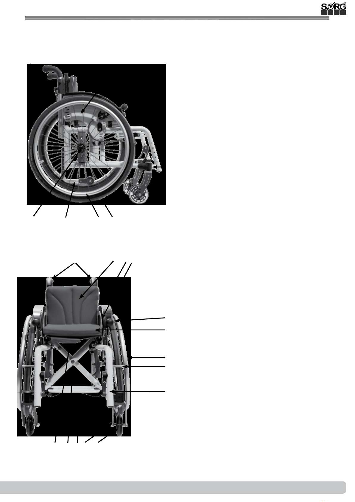
1 Wheelchair overview 5
2 General information 6
2.1 General indications 6
2.2 Documentation indications 6
2.3 Required torques and tools 6
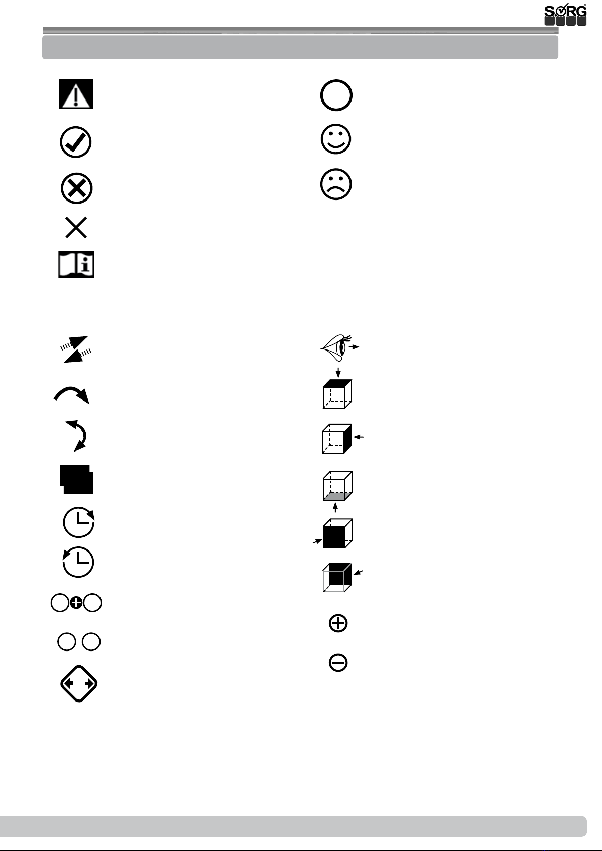
2.4 Explanation of symbols 7
2.5 General safety instructions 8
3 Assembly groups 9
3.1 Assembly group wheels 9
3.1.1 Centre of gravity 9
3.1.2 Seat height in front 9
3.1.3 Seat height in back, seat slant 10
3.1.4 Steering head slant 10
3.1.5 Replacing/ displacing the caster
adapters and casters 11
3.1.6 Camber 11
3.1.7 Rear wheel track balance 12
3.2 Assembly group seat 15
3.2.1 Changing the seat cover 15
3.2.2 Extending the seat depth with a
seat cover 15
3.2.3 Retightening the seat cover 15
3.2.4
Changing the seat depth of the SitzFix
15
3.2.5 Chaning the seat width 16
3.3 Assembly group leg support 17
3.3.1 General Information Leg supports 17
3.3.2 Leg support outer attachment,
folds up sideways 17
3.3.3 Leg support 18
3.3.4
Divided foot plate, folds up sideways
18
3.4 Assembly group side guards 19
3.4.1 Setting side guards 19
3.4.2 Skirt guard on the side guard 19
3.4.3 Armrest on the side guard 20
3.5 Assembly group brake 21
3.5.1 General information brake 21
3.5.2 Standard wheel lock 21
3.5.3 Cable brake 22
3.5.4 Drum brake 22
3.6 Assembly group anti-tipper 23
3.6.1 Height setting 23
3.6.2 Length setting 23
3.7 Assembly Group tipping lever 24
3.7.1 Mounting 24
3.8 Assembly Group back 25
3.8.1 Adjustable back cover 25
3.8.2 Firm curved back plate 25
3.8.3 Stabiliser bar 25
3.8.4 Setting the back angle 26
3.8.5 Extension on the standard backs 26
3.8.6 Extension on backs with angle
adjustment or setting 26
3.9 Assembly Group Truss Pads 27
3.9.1 Classication 27
3.9.2 Vertical setting 27
3.9.3 Horizontal setting 27
3.9.4
Fine adjustment of the truss pad holder
28
3.9.5 Adjusting to the user 28
3.10 Assembly Outdoor Front End 29
3.10.1 General Information 29
3.10.2 Widen 29
3.10.3 Extend 29
4 Repairs and maintenance 31
4.1 Repairs 31
4.2 Spare parts 31
4.3 Maintenance 31
4.4 Disinfection 31
4.5 Storage 31
4.6 Reinstatement 32
4.7 Disposal 32
4.8 Maintenance/ Inspection 32
5 Technical specications 34
5.1 Daten und Maße 34
5.2 Meaning of labels 35
5.3 Declaration of conformity 35

4 of 36 Service Record Jump alphaService Record Jump alpha 2019-07-16

Service Record Jump alpha 5 of 36
2019-07-16
1 Wheelchair overview
1push handle
2back
3side guard
4skirt guard
5wheel lock
6seat
7frame
8caster housing
9caster fork
10 caster
11 rear wheel
12 handrim
13 anti-tipper
14 quick-release axle
15 push handle
16 back
17 skirt guards
18 side guards
19 brake lever
20 seat cushion
21 handrim
22 brake bolt
23 frame
24 caster
25 caster fork
26 contiuous legsupport
27 crossbrace
28 utensils bag
12 3 45
7
8
9
10
111214 13
6
24252627
28
15 16 17 18
19
21
22
23
20

6 of 36 Service Record Jump alphaService Record Jump alpha 2019-07-16
2 General information
2.1 General indications
In the following all individual settings, adjustments and repairs as well as the yearly inspection of
the wheelchair are described. These adjustments require tools and specialised knowledge. Ple-
ase leave the adjustments to a qualied rehab consultant.
Should questions or suggestions come up then please contact your medical supply store or our
team (+49 7254 9279-0).
2.2 Documentation indications
Please note:
• Information about before sale can be found in the instructions for use
• Infomation for the user can be found in the instructions for use
• For maintenance instructions see: Chapter 4 (Repair & Maintenance)
2.3 Required torques and tools
For the following screws needed torque:
• M5: 5 Nm;
• M6: 7 Nm;
• M6 (axle plate) 10 Nm
• M8: 20 Nm;
• M10 (nut): 25 Nm; (caster)
• quick release axle tting 40 Nm
Needed tools:
• torque wrench (5-50 Nm)
• open end wrench
• ex ratchet handle with socket wrench inserts
• hexagon screw driver
• Phillips screw driver
• at head screw driver
• plastic mallet
• side cutter
• threadlocker (uid)
• bicycle inner tube repair kit
• work bench/jaw vise with rubber pads

Service Record Jump alpha 7 of 36
2019-07-16
2 General information
2.4 Explanation of symbols
ATTENTION! Warnings for perso-
nal Safety aspects that are of the
utmost importance.
CORRECT safety adjustment/ use
WRONG adjustment/ use
NOT ALLOWED
References to additional/conti-
nuing reading.
Setting or adjusting the angle
open/ close
Turn clockwise
Turn counter-clockwise
steps to be done at the same
time
steps to be done after each other
steps to be done on both sides
Use
(A); (B)
1. 1.
1. 2.
;
2x
push/ pull/ insert / move/
Push in specic direction
important detail
correct or proper use/setting
incorrect or improper use/setting
reference from text to detail
point of view
view from top
view from the side
view from the bottom
view from the front
view from the back
fasten parts
remove parts

8 of 36 Service Record Jump alphaService Record Jump alpha 2019-07-16
2 General information
2.5 General safety instructions
Before each use be sure to check:
• frame, back tubes, attachments and accessories for visible damage, bends, cracks or mis-
sing/loose scews,
• wheels/quick release axles for rm t,
• sucient tire pressure, tire tread,
• functionality of the brakes,
• rm t of the angle adjustment elements/ eccentric clamps,
• rm t of the seat plate/ the back/ the foot plate,
• functionality of the anti-tipper/ seat and back straps,
• if all previously disassembled parts are re-inserted or rmly locked.
There is a risk of injuries (e. g. such as bruising) on all rotating or folding parts, including
adjustments, repairs and transport.
All wheelchair parts are to be handled with care. Do not throw or drop removable parts.
Before repairs or adjustments are made, clean/didinfect the wheelchair and secure it from
tipping over and/or falling down.
Only use original spare parts.
Safety nuts may only be used once. Lossened safety nuts must be replaced by new ones.
Only the regular maintenance of all safety-relevant parts on the wheelchair by a qualied
rehab workshop protects against damage and maintains our manufacturer's warranty.
Combination with products from other manufacturers
The wheelchair may only be combined with the electrical auxiliary drives apporved by the
manufacturer. Restrictions or adaptations as well as the attachment itself must be done by the
supplier of the additional system or the authorized specialist dealer.
Please check the conditions with the manufacturerer of the audiliary drives.
In combination of wheelchair and electric auxiliary drive, certain strains can occur which
can lead to damage to the wheelchair. Slowly approach obstacles and carefully overcome
them so that little force is applied to the caster, driving wheel and wheelchair as a whole.

Service Record Jump alpha 9 of 36
2019-07-16
3.1 Assembly group wheels
(1)
(A) (B)
(2)
(A)
(B)
3.1.1 Centre of gravity
(1)To set the centre of gravity
• remove both rear wheels,
• remove all screws (A)
• displace the perforated plate in the alter-
native holes (B).
• Displacement must occur parallel on
both sides.
• Replace screws and tighten them.
After every change made on the rear
wheels, the wheel lock must be newly adjust-
ed.
Slowly go to the maximum and from the
user (!) wanted point of wobbliness.
The more you move the casters back, the higher the risk that the wheelchair will tip forward
when getting in or out.
The more you move the rear wheels with the perforated plate forward, the higher the risk that the
wheelchair could tip backward.
Please make sure, that with the seat slant the grip point and grip direction are not aected by a
too high placement of the rear wheels.
3.1.2 Seat height in front
(2) The seat height is set by the position of the
casters in the caster fork.
• remove the connection caster/caster
fork (A) completely,
• mount the casters on both sides in the
wanted holes (B),
• retighten all screws.
After every change you must check the vertical
steering head slant and, if necessary correct it
(see chapter steering head slant).
In the mounting parts of the casters, hair,
lint, dirt, etc. can collect, whereby the casters
become hard to use. Remove the casters in
short intervals and clean the forks, axles and
the husks thoroughly.
Precede the same with synthetic forks.

10 of 36 Service Record Jump alphaService Record Jump alpha 2019-07-16
3.1 Assembly group wheels
(A)
(1) (2)
(C)
(B)
(3)
(B)
(C)
(A)
3.1.3 Seat height in back, seat slant
After each change made on the rear wheels the functionality of the wheel lock must be
checked and the casters must be newly adjusted.
Generally, the seat height in back is about 2-3 cm lower as in front, for a safe and comfortable seat
position with a good distribution of the seat pressure and to avoid a “sliding out”. However, other
settings in individual cases can also be useful.
• (1) Remove the rear wheels,
• remove the side guards/skirt guards with
the screws (A) (easily remove the desk
side guard)
• (2) remove the quick-release axle tting
including all washers in the alternative
holes (C)
• and retighten all screws. (tightening
torque nuts M18 tting 35Nm).
• Mount the side guards and place the rear
wheels back in the quick-release axle.
The ttings must stick out of the perforated plate at the same length on both sides. The ttings
can only stick out so that the side distance of the tires to the side guard is as low as possible,
however a min. of 10mm.
3.1.4 Steering head slant
After every change on the rear wheel, the steer-
ing head slant must be newly adjusted.
To adjust the caster adapter:
• (3) remove all screws (A) on both (!)
sides,
• remove both screws (B).
• By tuning the adjust washer (C) (with a
at head screw driver) place the adapter
in a vertical position (using an angle).
• Retighten all screws; screws (A) with 9
Nm, screw (B) with 7 Nm.
A falsely set steering head slant can lead to the casters shaking back and forth and can lead to
hindering curve rides (from casters).

Service Record Jump alpha 11 of 36
2019-07-16
3.1 Assembly group wheels
(1)
(A)
(B)
(C)
(3)
(B)
(C)
(A)
(D)
(E)
(2)
(A)
(B)
(C)
• (1) Remove the caps (A) on both sides,
• remove all screws (B) on both sides
• and remove also the distance pieces, if
necessary.
• Replace the caster adapters with new
ones and/or displace them in the alter-
native holes (C).
• Replace all screws (if necessary also the
distance
3.1.5 Replacing/ displacing the caster adapters and casters
Through the camber you inuence:
• the side tilt stability,
• the shoulder rear wheel position and
• the track width of the wheelchair.
(2) To avoid the so called “eraser eect” we gen-
erally mount the tting track balance ex-works
(A). With a change of the camber afterwards,
the track balance adapter (A) must be replaced
by one that ts (spare part).
With a camber of 8° a distance block to the
wheelbase extension is necessary (spare part).
Adjusting the camber
• (3) Remove the rear wheels,
• remove screws (A) and move them in
the alternative holes (B),
• retighten the screws.
For a camber of 8°:
• (3+1 next page) remove the screws (A),
• remove the screws (C),
• move the perforated plate holder (D) by
turning it 180° on the outer part of the
frame tube,
• replace the screws (C) and tighten them,
• replace the perforated plate with the
screws (A) and tighten them.
The setting may not be possible if you wish to
widen the seat, being that then you would have
to turn the quick-release axle ttings too far out
of the perforated plate.
Check/correct the distance of the rear wheel to
the side guard and skirt guard by attaching the
rear wheel.
3.1.6 Camber

12 of 36 Service Record Jump alphaService Record Jump alpha 2019-07-16
3.1 Assembly group wheels
(1)
(D)
(B)
innen außen
The tire of the wheel must be at least 10 mm
away from the side guard/skirt guard. Take no-
tice that the distance on the left and right are
the same!
(1) In order to screw on or screw o the
quick-release axle ttings:
• remove the screws of the ttings (B)
(the lock nut (2E) on the inner surface
as well),
• turn the whole tting (C) in the wanted
position and
• retighten the screws (tightening torque
nuts M18 tting 35 Nm).
You must check the functionality of the
knee lever brake and if necessary reset them.
3.1.7 Rear wheel track balance
Version till 02/2017
If you have to change the camber and/or the seat slant you must, in order to avoid the so called
“eraser eect”, mount appropriate wedge plates for the track balance.
To change/set the wedge plate;
• (1) remove the screws (A) of the quick-re-
lease axle ttings (D) (also on the inside),
• apply the needed wedge plate/s (B),
• the mounting grooves (C) must point
forward in driving direction,
• replace all other washers
• and retighten the screws (A) of the
quick-release axle ttings (D) (also on
the inside)
(turning point 35 Nm).
Use the following chart the help you:
cam-
ber
without seat
slant
normal seat
slant (< 5°)*
strong seat
slant (> 5°)*
2° washer 0° washer 0° wedge plate
0,5°
4°-8° washer 0° wedge pla-
te0,5°
wedge plate
1°
11° washer 0° wedge plate
1°
wedge plate
1°**
**If necessary, apply 2 sets of plates (2 x inner plate
mounted on the inside, 1x outer plate+ 1x inner plate
mounted on the outside)
You must check the functionality of the
knee lever brake and if necessary reset it.
(2)
(A)
(A)
(B)
(B)
(C)
(C)
(D)
The picture shows in driving direc-
tion the perforated plate on the
right.

Service Record Jump alpha 13 of 36
2019-07-16
3.1 Assembly group wheels
(A)
(B)
(C)
(1)
The tires of the wheel must be at least 10 mm
away from the side panel or clothing guard.
Pay attention to the same distance left and
right!
(1) To insert or remove the quick-release axle
tting:
• loosen the screw connection (B) of the
tting (also the lock nut (2E) on the
inside),
• Turn the complete tting (C) to the
desired position and
• Tighten all screw connections again
(tightening torque of nuts M18 tting
35 Nm).
Be sure to check the functionality of the
knee lever brake and adjust if necessary.
Please note the colored discs for the correct
adjustment of the camber.
(2)
(A)
(E)
Version from 02/2017
The wheelchair is delivered with the appropriate toe-in, depending on the wheel camber adjust-
ment and attachment of the steering and pushing aid. When changing the camber or retrotting
the steering or pushing aid, it may be necessary that the toe must be changed.
(1) In order to avoid the so-called "eraser
eect", we generally assemble the matching
track compensation (A) at the factory. If the
camber is subsequently changed, it may be
necessary to replace the track compensation
adapter (A) with a suitable one (spare part).
To change toe-in:
• Remove rear wheels,
• and remove screw connection (B + C).
• Depending on the mounting variant
and camber, please observe the instruc-
tions on the following pages.
• After changing the toe settings:
• replace the screws (B + C) and tighten
the screws (B).
• Check / correct the distance between the rear wheel and the side part or clothing protec-
tion by attaching the rear wheel.

14 of 36 Service Record Jump alphaService Record Jump alpha 2019-07-16
3.1 Assembly group wheels
Illustration shows the mounting on the right
red
blue black
green
black
green
rot
blue
(1)
54
3b 3a
2
1
3a 3b
45
1° 0,5°
0,5° 1°
red
blue
black
green
black
green
blue
red
Illustration shows the mounting on the left
(2)
1° 0,5°
0,5° 1°
54
3b 3a
2
1
3a 3b
5
4
(1+2) Assembly of track compensation:
pos.-
nr.
count description
1 1 Screwed M18*1, d=12
2 1 reinforcement axle plate
3a 2 fall-in-track disc 0,5°
3b 2 fall-in-track disc 1,0°
4 2 locking washer S18
5 2 nut M18x1 SW24
For Vector and Jump beta 8 ° camber, as well as Jump alpha 5 ° and 8 ° camber, a spacer block
for wheelbase extension is required (spare part). Here, the toe is already integrated in the broa-
dening.
Which disc has to be used at which setting:
Camber Without seat tilt
0° without track disc
2° without track disc
4-8° without track disc
Camber Normal seat tilt (ca. 5°)
0° without track disc
2° without track disc
4-8° track disc with 0,5°
Camber Strong seat tilt
0° without track disc
2° track disc with 0,5°
4-8° track disc with 1°
For the steering and pushing aid, at least the 0.5 ° track disc must always be mounted
(except for a camber of 0 ° in which no track disc is used).

Service Record Jump alpha 15 of 36
2019-07-16
3.2 Assembly group seat
(B)
(3)
(A)
(C)
(B)
(2)
(A)
(C)
(A)
(B)
(1)
(A)
(4)
3.2.1 Changing the seat cover
3.2.2 Extending the seat depth with a seat cover
3.2.3 Retightening the seat cover
3.2.4 Changing the seat depth of the SitzFix
(1) To change the seat cover, remove both
screws (A) on the bottom of the seat tube. Pull
the seat cover (B) forward, out of the tube (C).
Thread the new seat cover on to the cover rods.
Guide the seat cover back in to the seat tube
(C). Finally, screw the screws (A) back on.
With an available seat extension, proceed the
same way.
(2) Remove the screws (A) of the seat extension
parts (B) on both sides and pull them togeth-
er with the seat cover in the wanted position.
Screw the screws on tightly.
(3) Remove the screws (A) on both sides and
pull the seat cover completely out of the slots
of the seat tubes (if necessary, together with the
extension pieces (B).
Place the Velcro connections (C) in the new po-
sition, guide the cover back in the slots of the
seat tubes (B) and screw it back on at the bot-
tom (A).
The seat depth of a SeatFix can only be reached
by the optional seat extension.
(4) Loosen the screw connections (A) under the
seat, pull the extension in the wanted position
and retighten the screw connections.

16 of 36 Service Record Jump alphaService Record Jump alpha 2019-07-16
3.2 Assembly group seat
The seat width of a Jump can be changed 1 cm on each side with spacers between frame and side
guards. The parts required for this are sent in a pouch in the utensil bag under the seat cover (6
round spacers plus the necessary screws).
Remove the rear wheels and the cushions or SeatFix.
3.2.5 Changing the seat width
(1) Remove the side guards by removing all
screws (A) on both sides.
(2) Displace both quick release axle adapters
(B) 1 cm outward.
Place the respective included spacers on the
pre-existing spacers (2C+3D),
exchange the pre-existing screws for the in-
cluded longer ones and with them, attach the
spacers and the side guards tightly to the frame
tube.
Afterwards, check the functionality of the
wheel lock and if necessary, correct its posi-
tion.
(A)
(1)
(D)
(3)
(C)
(2)
(B)

Service Record Jump alpha 17 of 36
2019-07-16
3.3 Assembly group leg support
(3) (4)
(1) (2)
(5)
Model 1: Model 2:Model 3:Model 4:
Model 5:
The leg rest is optimally adjusted when the leg
is at a right angle to the foot plate and the en-
tire thigh is up to about the width of the knee
in the seat cushion / seat shape part on lies.
3.3.1 General Information Leg supports
3.3.2 Leg support outer attachment, folds up sideways
Setting the lower leg length
(6) Remove the screws (A) on the outer side of
the frame, including the screws and bushings
(B) on the inner side, on both sides. Choose the
new position, replace the screws and bushings
and tighten them.
Setting the depth
(7) The foot plate can be attached in 3 posi-
tions. Remove all screws and nuts (A) on the
foot plate and reposition the foot plate. Replace
all screws and nuts and retighten them.
Setting the angle
(8) Turn the cylinder screws (B) in the clamp on
both sides far enough until the clamp connec-
tion loosens. Set the wanted angle and retight-
en the screws.
The ne adjustments of the locking claw occurs
the same with all continuous foot plate types.
(A)
(B)
(C)
(6)
(A)
(C)
(B)
(7)

18 of 36 Service Record Jump alphaService Record Jump alpha 2019-07-16
3.3 Assembly group leg support
3.3.3 Leg support mounting outside
Setting the lower leg length
(1) Remove the screws (A) on the outer side of
the frame, including the screws and bushings
(B) on the inner side, on both sides. Choose the
new position, replace the screws and bushings
and tighten them.
Setting the depth
(2) The foot plate can be attached in 3 posi-
tions. Remove all screws and nuts (A) on the
foot plate and reposition the foot plate. Replace
all screws and nuts and retighten them.
Setting the angle
(3) Turn the cylinder screws (B) in the clamp on
both sides far enough until the clamp connec-
tion loosens. Set the wanted angle and retight-
en the screws.
The ne adjustments of the locking claw occurs
the same with all continuous foot plate types.
(1)
(A)
(B)
(A)
(2) (3)
(B)
3.3.4 Divided foot plate, folds up sideways
The divided foot plate is not suitable for users with tone dysregulation.
The foot plates are set horizontal ex works. Should the plates tilt in the course of use, they can be
adjusted as follows:
Fine adjustment of foot plate angle, inner at-
tachment
(4) Loosen the locking nut (A), turn the set
screw (B) in the wanted position and retighten
the locking nut (A).
Fine adjustment of foot plate angle, outer at-
tachment
(5) Loosen the locking nut (A), turn the set
screw (B) in the wanted position and retighten
the locking nut (A).
(4)
mounting
inside
(A)
(B)
mounting
outside
(5)
(B)
(A)

Service Record Jump alpha 19 of 36
2019-07-16
3.4 Assembly group side guards
3.4.1 Setting side guards
(1a+b) The inner space between wheel and side guard should be at least 10 mm distance so
that in case of side strain the side guard does not rub on the wheel cover.
(2) Upward, the outline of the side guard should have a distance of at least 10 mm as long as it is
parallel to the outline of the rear wheel.
High settings can become hazardous for active
drivers.
(2) To set the height, remove the rear wheels.
Remove the screw connections (B) in the front
and back. Change the position of the side
guard, replace the screws and retighten them.
(1a)
ca. 10 mm
(1b)
min. 10 mm min. 10 mm
(B)
(2)
(3) The skirt guard is placed on the side guard
and should cover the rear wheel to the outer
side of the wheel.
When repositioning the rear wheels in the
front perforated plate, the skirt guards must be
placed in the alternative holes (A). Remove the
screws (B), move the skirt guard, replace all of
the screws and retighten them.
The distance between the upper part of the
wheel and skirt guard should be at least 10 mm
so that the skirt guard does not push the strain
on to the wheel.
3.4.2 Skirt guard on the side guard
(A)
(B)
(4)
(3)
maximal

20 of 36 Service Record Jump alphaService Record Jump alpha 2019-07-16
3.4 Assembly group side guards
3.4.3 Armrest on the side guard
(1) To set the arm rests remove the screws (A)
on both sides, place the cushion in the holes
to the wanted position, replace the screws and
retighten them.
(1)
(A)
Other manuals for Jump alpha
2
Table of contents
Other SORG Wheelchair manuals

SORG
SORG kika User manual

SORG
SORG Jump beta User manual

SORG
SORG Tilty vario Service manual

SORG
SORG Dynamis MV Service manual

SORG
SORG Mio Service manual

SORG
SORG Jump beta User manual

SORG
SORG Tilty vario User manual

SORG
SORG LoopSORG 802 User manual

SORG
SORG Dynamis MV 793 User manual

SORG
SORG Airon 792 User manual
Popular Wheelchair manuals by other brands

Sunrise Medical
Sunrise Medical Jay Active Back User instruction manual & warranty

Pressalit Care
Pressalit Care PLUS R7124 Mounting instruction

panthera
panthera U3 Light Y-Front operating instructions

Drive
Drive Inspired Supreme BCCS-8510S instructions

R82
R82 Strong Base user guide

Decon wheel
Decon wheel Rehatec Galileo Assembly instructions