Service record Dynamis MV 3 von 36
2021-01-12
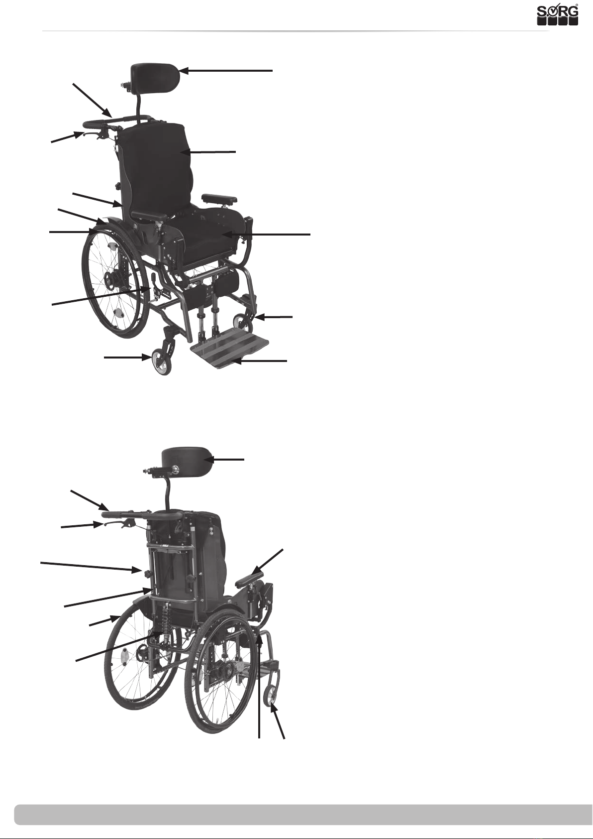
1 The wheelchair at a glance 4
2 General information 5
2.1 General information service booklet 5
2.2 Documentation notes 5
2.3 Required torques and tools 5
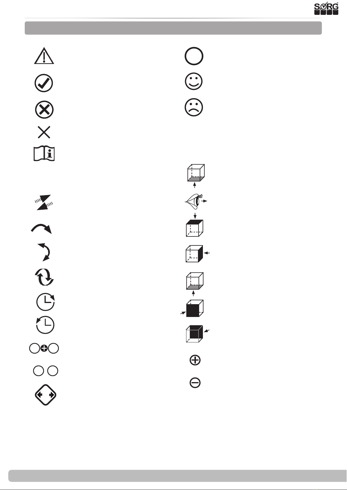
2.4 Explanation of symbols 6
2.5 General safety information 7
3 Assemblys 8
3.1 Wheel assembly 8
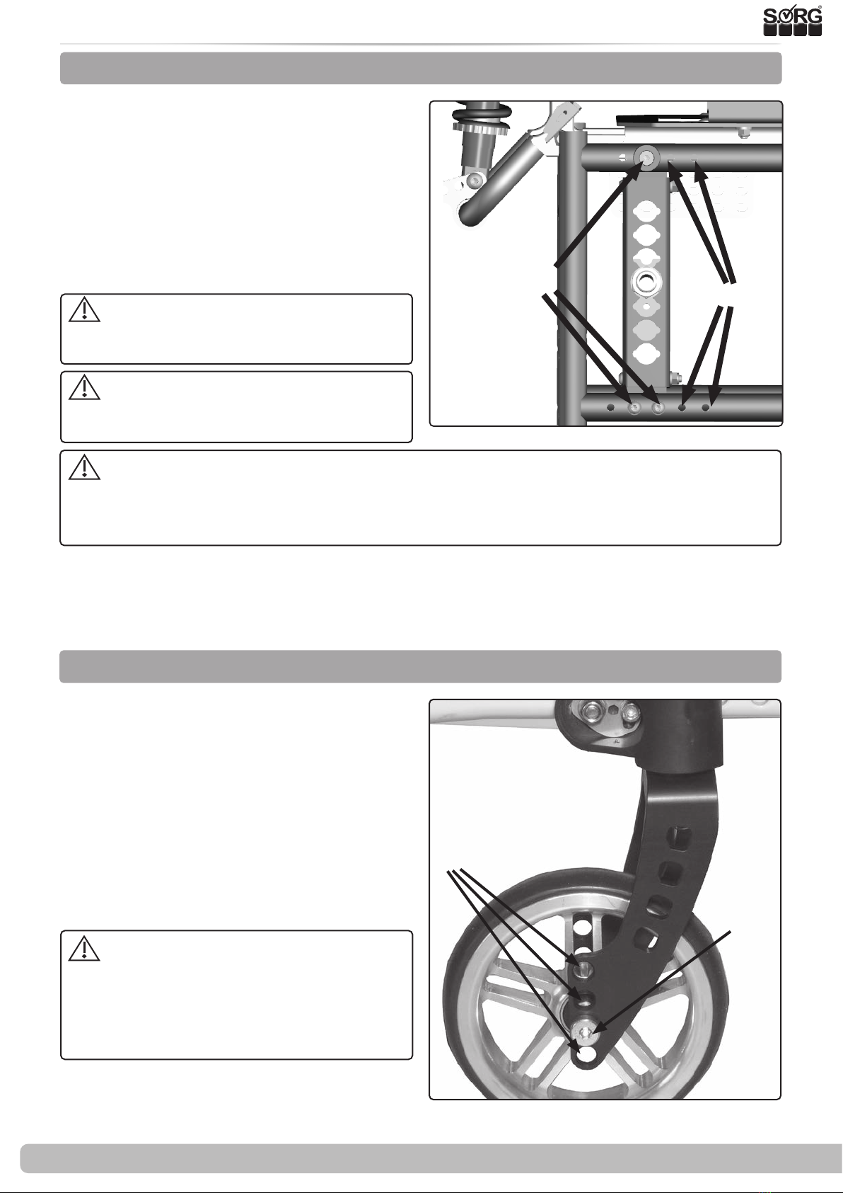
3.1.1 Center of gravity (wheelbase / perfo-
rated plate) 8
3.1.2
Adjustment of the seat height by
changing the position of the caster wheel
8
3.1.3 Rear seat height, seat inclination 9
3.1.4 Caster head tilt 9
3.1.5 Replacement / relocation of the caster
wheel adapters and caster wheels 10
3.1.6 Camber 10
3.1.7 Track compensation drive wheels 11
3.2 ERGO-seat assembly 12
3.2.1 General information about the ERGO
seat 12
3.2.2 Removal of the ERGO seat 12
3.2.3 Axis of rotation seat part / back part 13
3.2.4 Growth in seat depth ERGO seat 13
3.2.5 Adjusting the seat height 13
3.2.6 Increase seat width ERGO seat and back
unit 14
3.3 Frame assembly 15
3.3.1 Frame widening 15
3.4 Back assembly 16
3.4.1 Setting dynamic back 16
3.4.2 Back angle adjustment 16
3.5 Legrest assembly 17
3.5.1 Adjustment of the legrest 17
3.5.2 Adjustment of the depth 17
3.5.3 Adjusting the height 18
3.5.4 Preset opening angle 18
3.5.5 Height adjustment of the calf support18
3.5.6 Height adjustment of the footrest 19
3.6 Brakes assembly 20
3.6.1 General information about the brake
20
3.6.2 Standard parking brake 20
3.6.3 Drum brake 21
3.7 Anti-tipper assembly 22
3.7.1 Height adjustment 23
3.7.2 Length adjustment 23
3.8 Tilt bracket assembly 24
3.8.1 Mounting 24
3.9 Headrest assembly 25
3.9.1 Height adjustment 25
3.9.2 Depth adjustment and dynamics of the
headrest 25
3.9.3 Adjust the inclination 25
3.10 Abduction wedge assembly 26
3.10.1 Depth adjustment 26
3.10.2 Height adjustment 26
3.11 Lateral support assembly 27
3.11.1 Nomenclature 27
3.11.2 Vertical adjustment 27
3.11.3 Horizontal setting 27
3.11.4 Fine adjustment of the lateral support
holder 28
3.11.5 Adaptation to the user 28
4Repairs / maintenance / re-use 29
4.1 Rapairs 29
4.2 Spare parts 29
4.3 Cleaning 29
4.4 Disinfection 29
4.5 Storage 29
4.6 Lifespan 30
4.7 Re-use 30
4.8 Disposal 30
4.9 Maintenance / inspection 30
5 Technical data 31
5.1 Data and dimensions 31
5.2 Meaning of the labels 32
5.3 Declaration of Conformity 32
Contents