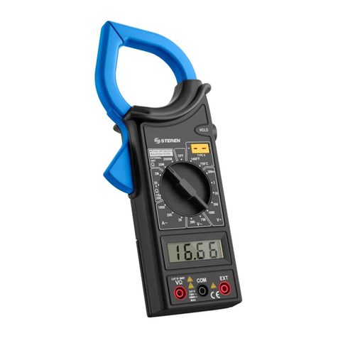
Steren MUL-100 User manual

Product / Producto: DIGITAL CLAMP
MULTIMETER / MULTÍMETRO
DIGITAL DE GANCHO
Model / Modelo: MUL-100
Brand / Marca: Steren
CONDICIONES
1. Para hacer efectiva esta garantía se requiere: La presentación de esta póliza y del producto, en el lugar en donde fue adquirido o en ELECTRONICA STEREN S.A. DE C.V.
2. ELECTRONICA STEREN S.A. DE C.V. se compromete a reparar el producto en caso de estar defectuoso sin ningún cargo al consumidor.
3. El tiempo de reparación en ningún caso será mayor a 30 días contados a partir de la recepción del producto en cualquiera de los sitios en donde pueda hacerse efectiva la
garantía.
4. El lugar donde puede adquirir partes, componentes, consumibles y accesorios, así como hacer válida esta garantía es: En cualquiera de las direcciones arriba mencionadas.
ESTA GARANTIA NO ES VALIDA EN LOS SIGUIENTES CASOS:
1. Cuando el producto ha sido utilizado en condiciones distintas a las normales.
2. Cuando el producto no ha sido operado de acuerdo con el instructivo de uso.
3. Cuando el producto ha sido alterado o reparado por personas no autorizadas por ELECTRONICA STEREN S.A. DE C.V.
Nota: El consumidor podrá solicitar que se haga efectiva la garantía ante la propia casa comercial, donde adquirió el producto. Si la presente garantía se extraviara, el
consumidor puede recurrir a su proovedor para que le expida otra póliza de garantía, previa presentación de la nota de compra o factura respectiva.
DATOS DEL DISTRIBUIDOR
DISTRIBUTION / NOMBRE / DISTRIBUIDOR:
ADDRESS / DOMICILIO:
PRODUCT / PRODUCTO: BRAND / MARCA:
MODEL / MODELO: SERIAL NUMBER / No. DE SERIE:
DATE OF DELIVERY / FECHA DE ENTREGA:
Call Center / Centro de Atención a Clientes
del Interior 01 800 500 9000
Mexico City / Cd. de México: 53 54 22 90
Warranty
CONDITIONS:
1. This warranty card with all the required information, the invoice or purchase ticket, the product box or package, and the product, must be presented with the product
when warranty service is required.
2. If the product stills on the warranty time, the company will repair it free of charge even the transportation charges.
3. The repairing time will not exceed 30 natural days, from the day the claim was received.
4. Steren sells parts, components, consumables and accessories to customer, as well as warranty service, at any of the following addresses:
THIS WARRANTY IS VOID ON THE NEXT CASES:
If the product has been damage by an accident, acts of God, mishandling, leaky batteries, failure to follow enclosed instructions, improper repair by unauthorized
personal, improper safe keeping or otherwise.
Notes:
a) The customer can also claim the warranty service on the purchase establishment.
b) If you lose the warranty card, we can reissue it just showing the invoice or purchase ticket.
Póliza de Garantía
This Steren product is warranted under
normal usage against defects in
workmanship and materials to the original
purchaser for one year from the date of
purchase.
Garantiza este producto por el término de
un año en todas sus partes y mano de
obracontracualquierdefectodefabricación
y funcionamiento, a partir de la fecha de
entrega.

INSTRUCTIVO DE USO DE MULTÍMETRO DIGITAL DE GANCHO
Modelo: MUL-100
Marca: Steren
Antes de utilizar su nuevo Multímetro Digital de Gancho lea este
instructivo para evitar cualquier mal funcionamiento. Guárdelo para
futuras referencias.
Su nuevo equipo está diseñado para ser usado por ingenieros, técnicos y
aficionados, quienes demandan un instrumento que sea preciso, seguro,
portátil y siempre listo para ser usado. Cada una de las posiciones de
prueba es rápida y fácilmente seleccionada con un simple giro del
interruptor selector. Cuenta con 3 ½ dígitos y pantalla de LCD, con función
de aislamiento (con opción 500V).
CARACTERÍSTICAS
Medición de voltaje DC (V )
Medición de voltaje AC (V~)
Medición de corriente AC (V~)
Medición de resistencia
Medición de temperatura
INSTRUCCIONES DE SEGURIDAD
Para evitar una descarga eléctrica, cuando esté midiendo altos voltajes
hágalo con precaución.
Siempre desconecte el circuito que se encuentra bajo prueba antes de
conectar las puntas de prueba.
Antes de utilizar la perilla selectora de rangos, desconecte las puntas de
prueba.
Nunca opere el multímetro más de la máxima tolerancia indicada.
Cuando lleven a cabo mediciones en televisores o circuitos de poder
(potencia) interrumpidos, podría habar pulsos de voltaje con altas
amplitudes lo cual puede dañar el amperímetro.
Sea cuidadoso cuando trabaje con voltajes alrededor de 60VCD (V ) ó
30VCA rms (V~).
Mantenga los dedos detrás de las barreras de prueba mientras se realicen
las mediciones.
Desconecte las puntas de prueba de todas las fuentes de corriente
eléctrica antes de abrir el amperímetro.
No utilice el amperímetro si la cubierta de la batería no está en su lugar y
completamente cerrada.
Siempre utilice un paño suave, limpio y ligeramente humedecido para
limpiar el equipo.
SIGNIFICADO DE SÍMBOLOS
Alerta al usuario de presencia de un voltaje peligroso no a
segurado dentro del producto. Puede ser de suficiente
magnitud para constituir un riesgo de choque eléctrico para las
personas.
Información de seguridad importante.
Tierra.
INSTRUCTION MANUAL FOR DIGITAL CLAMP MULTIMETER
Model: MUL-100
Brand: Steren
Before using your new Digital Clamp Multimeter, please read this
instruction manual to prevent any damage. Put them away in a safe
place for future references.
Your new multimeter has been designed for engineers, technicians and
amateurs whom demands an exact, trustworthy, portable and always
ready to use device. Each test positions are easy and quick to use, only
with a simple turn of the range switch. It counts with a LCD screen and can
display up to 3 ½ digits. Also, it has an insulation tester (with 500V option).
CHARACTERISTICS
DC voltage measuring ( )
AC voltage measuring (V~)
AC measuring (V~)
Resistance measuring
Temperature measuring
SAFETY INSTRUCTIONS
To avoid shock hazard, do the high voltage measures, carefully.
Always disconnect the tested circuit before connecting testing leads.
Before to use the range switch, disconnect the testing leads.
Never operate this multimeter over the maximal indicated tolerance.
When you use this multimeter on TV sets or interrupted power circuits,
could have voltage pulses with high amplitudes and may cause damages
on the ammeter.
Be careful when you manage with high voltages around 60VDC (V ) or
30 VAC rms (V~).
Keep the fingers in back of the test barriers, during measuring.
Unplug the test leads from all the electrical current before to open the
ammeter.
Never use the ammeter if the battery cover is not placed correctly.
Only clean with a soft, damp cloth.
SYMBOLS
This symbol is an alert. Probably there is a dangerous voltage inside of the
equipment. May cause damages or an electric shock to people.
This symbol alerts you about important security information.
Ground terminal

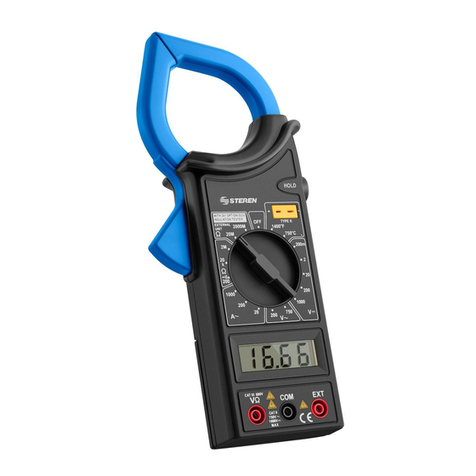
CONTROLS
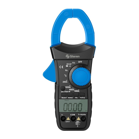
1.- Clamp ................................ Measures the magnetic field from a wire
2.- Clamp button ..................... Open or close the clamp fingers
3.- Data hold ………………….. Data hold for an easy reading
4.- LCD screen
5.- Range switch .................... Select the ranges and functions
6.- Input jacks ......................... Plug in the testing leads
CLAMP FINGERS
Put the wire with AC current (A~) in the middle of the clamp fingers,
pressing the clamp button to open and drop it when you want to close the
clamp fingers.
INPUT JACKS
This equipment has three protected inputs against electrical shocks. When
you use the equipment plug the black testing lead to COM jack and the red
testing lead to V jack.
Red testing lead depends of the function:
Use the EXT input jack to make the isolation test through the Banana
plugs. You can obtain an isolation resistance measuring.
CURRENT FLOW MEASURING
1.- Set range switch to desired ACA position (A~). Clamp fingers will
measure the AC (~) amperes from the wires.
2.- When appears "1" on screen, it means that the range is higher or exists
an overload. You must change the range and verify the allowable input at
the multimeter.
DC / AC MEASURING
1.- Plug the black testing lead to COM jack and the red testing lead to V
jack.
2.- Set the range switch to DC ( ) or AC (V~). Touch the tips of the test
leads to the measurement points.
Polarity on red testing leads will be indicated from the beginning with the
voltage value when you realize a DC voltage measuring (V ).
CONTROLES
1.- Gancho ……………….... Mide el campo magnético de un cable
2,. Botón de gancho ........... Abre o cierra los dedos del gancho
3.- Data Hold ……………… Retiene los datos de medición
4.- Pantalla de LCD
5.- Perilla de selección ........ Selecciona los rangos y funciones a
realizar.
6.- Entradas ......................... Conecte las puntas de medición
DEDOS DE GANCHO
Coloque el conductor de corriente de CA (A~) en medio de los dedos de
gancho presionando el botón de gancho para abrir y soltándolo para
cerrar el gancho.
ENTRADAS
Este equipo cuenta con tres entradas que están protegidas contra
sobrecargas. Durante su uso conecte la punta de medición negra a la
entrada COM y la punta roja a la entrada V
La punta roja depende de la función:
La entrada EXT se utiliza para aceptar en el equipo la prueba de
aislamiento a través de los plug tipo banana. Se obtiene una medición de
resistencia de aislamiento.
MEDICIÓN DE CORRIENTE QUE CIRCULA
1.- Coloque la perilla rotatoria a la posición ACA (A~) deseada. Los dedos
de gancho medirán los Amperes de CA (~) que circulan a través del
conductor.
2.- Cuando aparezca en la pantalla de LCD el número "1", significa que
hay una situación de sobre rango. Seleccione un rango más alto.
MEDICIÓN DE VOLTAJE
1.- Conecte la punta negra al la entrada COM y la punta roja a la entrada
V
2.- Coloque la perilla de selección en el rango VCD (V ) o VCA (~)
deseado y conecte las puntas de medición.
Polarity on red testing leads will be indicated from the beginning with the
voltage value when you realize a DC voltage measuring (V ).
Función Conexión punta roja Límites de entrada
Function Red Testing Lead Input limits
200mV V 250V DC (V ) / rms AC (~)
DC(V ), AC(V~) V 400V DC (V ) / 750 AC (~)
V 250V DC (V ) / rms AC (~)

3.- When appears "1" on screen, it means that the range is higher or exists
an overload. You must change the range and verify the allowable input at
the multimeter.
RESISTANCE MEASURING
1.- Connect the black testing lead to the COM jack and the red testing lead
to V jack.
2.- Set the range switch on the desired position. Touch the tips of the test
leads to the measurement points.
When appears "1" on screen, it means that the range is higher or exists an
overload. You must change the range and verify the allowable input at the
multimeter.
3.- If the resistance being measured is connected to a circuit, turn off the
power and discharge all capacitors, before applying test probes.
TEMPERATURE MEASURING
1.- Set range switch to desired C° position. On screen appears current
environment temperature.
2.- If you want to measure the temperature, put the thermocouple type "K"
on the temperature input jack. Put the other end of the thermocouple on
the object that you want to measure. Read the temperature value on the
display.
BATTERY REPLACEMENT
If the symbol "BAT" appears on screen, battery must be replaced with a
new one.
1.- Turn the multimeter off and remove the test leads of every measured
circuits.
2.- Remove the screws located in the bottom of the case and open the
box. Replace the battery.
3.- Replace the cover.
4.- Turn the multimeter on.
SPECIFICATIONS
Precision is specified for 1-year period after the calibration from 18°C to
28°C, with a relative humidity of 80%.
General
Maximum voltage: Between terminals and ground: 1000 VDC
(V ) or 750V rms AC (V~)
Power: 9V battery
Display: LCD screen (0-1999)
Measure method: Double integrated mode (analog / digital)
Overload indicator: On screen appears "1"
Polarity indicator: On screen appears "-" automatically
Operating environment: 0°C to 40°C
Storage environment: -10°C to 50°C
Battery indicator: On screen appears "BAT"
Dimensions: 37 x 90 x 230mm
Weight: 302g (battery included)
AC CURRENT (~)
Range: 20A, 200A, 1000A
Frequency range: 50Hz / 60Hz
Overload protection: 1200A in 60 s
AC VOLTAGE (V~)
Range: 200V, 750V
Input impedance: 9M
Frequency range: 50Hz / 500Hz
DC VOLTAGE (Vcc)
Range: 200V, 750V
Input impedance: 9M
RESISTANCE
Range: 200 , 20k , 2M
TEMPERATURE
Range: 0°F to 1400°F
Range: 0°C to 750°C
Note:
Product design and specifications are subject to change, without notice.
3.- Cuando aparezca en la pantalla de LCD el número "1" , significa que
hay una situación de sobre rango. Seleccione un rango más alto.
MEDICIÓN DE RESISTENCIA
1.- Conecte la punta negra a la entrada COM y la punta roja a la entrada
V
2.- Coloque la perilla de selección en la posición deseada y conecte las
puntas de medición.
Si la resistencia al ser medida excede el valor máximo del rango
seleccionado, en la pantalla de LCD se mostrará el número "1" indicando
sobre rango.
3.- Cuando se realice la medición de una resistencia en los circuitos, debe
tener cuidado de que éstos se encuentren sin energía y los capacitores
seencuentren completamente descargados.
MEDICIÓN DE TEMPERATURA
1.- Coloque la perilla de selección en la posición de °C. En la pantalla de
LCD se mostrará la temperatura ambiente.
2.- Si desea medir la temperatura, coloque el termoacoplador tipo "K" en
la entrada de temperatura y el otro extremo del termoacoplador en el
objeto que desee medir. La temperatura del objeto aparecerá en la
pantalla de LCD.
REEMPLAZO DE BATERÍAS
Si el símbolo "BAT" aparece en la pantalla de LCD, la batería debe ser re-
emplazada por una nueva.
1.- Asegúrese de que las puntas de medición estés desconectadas para
evitar choques eléctricos.
2.- Abra el compartimiento de baterías utilizando un desarmador y coloque
una nueva.
3.- Vuelva a colocar la tapa del compartimiento.
4.- Encienda el equipo.
ESPECIFICACIONES
La precisión es especificada por un período de un 1 año después de la
calibración de 18°C a 28°C con humedad relativa de 80%.
General
Voltaje máximo: Entre terminales y tierra: 1000 VCD (V )
ó 750V rms CA (V~)
Alimentación: Batería de 9V
Pantalla: LCD, 1999 lectura máxima
Método de medición: Sistema de conversión analógico digital,
cuenta con un convertidor A/D
Indicador de sobrerango: Aparece en la pantalla el número "1"
Indicador de polaridad: Aparece en la pantalla "-" automáticamente
Temperatura de operación: 0°C a 40°C
Temperatura de almacenamiento: -10°C a 50°C
Indicador de batería baja: En pantalla aparece el mensaje "BAT"
Dimensiones: 37 x 90 x 230mm
Peso: 320g (incluyendo batería)
Corriente CA (A~)
Rango: 20A, 200A, 1000A
Rango de frecuencia: 50Hz / 60Hz
Protección contra sobrecarga: 1200A en 60 s
Voltaje CA (V~)
Rango: 200V, 750V
Impedancia de entrada: 9M
Rango de frecuencia: 50Hz / 500Hz
Voltaje CD (Vcc)
Rango: 200V, 750V
Impedancia de entrada: 9M
Resistencia
Rango: 200 , 20k , 2M
Temperatura
Rango: 0°F a 1400°F
Rango: 0°C a 750°C
Nota:
El diseño del producto y las especificaciones pueden cambiar sin previo
aviso.
Other manuals for MUL-100
2
Other Steren Multimeter manuals

Steren
Steren MUL-015 User manual

Steren
Steren MUL-300 User manual

Steren
Steren MUL-280 User manual

Steren
Steren MUL-283 User manual

Steren
Steren MUL-057 User manual

Steren
Steren MUL-107 User manual

Steren
Steren MUL-010 User manual

Steren
Steren MUL-020 User manual

Steren
Steren MUL-605 User manual

Steren
Steren MUL-115 User manual

Steren
Steren MUL-005 User manual

Steren
Steren MUL-105 User manual

Steren
Steren MUL-050 User manual

Steren
Steren MUL-052 User manual

Steren
Steren MUL-100 User manual

Steren
Steren MUL-055 User manual

Steren
Steren MUL-030 User manual

Steren
Steren MUL-005 User manual

Steren
Steren MUL-095 User manual

Steren
Steren MUL-035 User manual