manuals.online logo
Brands
  1. Home
  2. •
  3. Brands
  4. •
  5. SUGATSUNE
  6. •
  7. Door Opening System
  8. •
  9. SUGATSUNE LAMP FD50-H User manual

SUGATSUNE LAMP FD50-H User manual

1
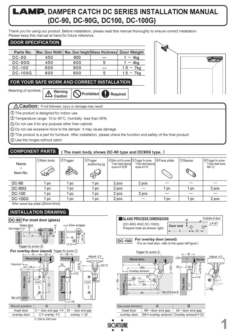
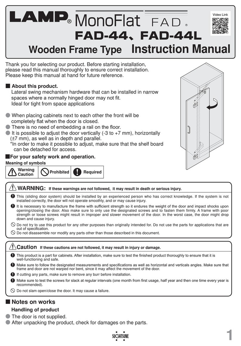
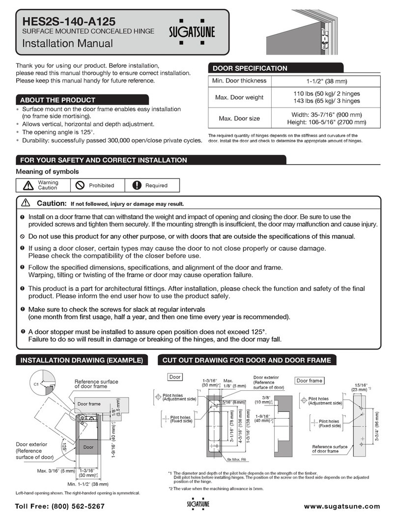
Thank you for using our product. Before installation, please read this manual thoroughly to ensure correct installation.
Please keep this manual at hand for future reference.
FD50-H SLIDING DOOR SYSTEM Installation Manual
(Surface Mount Roller, Standard Sliding) Part No.
FD50HMP
SPECIFICATIONS
●This product is a parts set for a sliding door system for
residential & commercial use.
●
The door can be installed without the use of tools.
Door height Max. 2400 mm 2401‑2700mm
Door width 774‑1500mm 800‑1500mm
Min. Door thickness 30 mm
Max. Door weight 50 kg / door
Vertical adjustment ±4 mm
ABOUT THE PRODUCT
FOR YOUR SAFETY AND CORRECT INSTALLATION
WARNING:

If not followed, death or serious injury may result.
Caution:
If not followed, injury or damage may result. 
This product should be installed by a qualified person in accordance with this manual. If it is not installed correctly, the door
may fall and cause injury.
Provide a frame that can withstand the weight and impact of opening and closing the door. Be sure to use the specified
screws and tighten them securely. If the mounting strength is insufficient, the door may fall and cause injury.
Do not try to use this product for anything other than its original purpose. Do not use any part for applications outside of its
specification.
Do not disassemble or modify any parts other than those described in this document.
Follow the specified dimensions, specifications, and alignment of the door and frame. Warping, tilting or twisting of the
frame or door may cause failure.
If cutting any parts, make sure to remove any burrs before installation. Also check the upper track for any left-over burrs or
scraps and remove these.
This product is a part for architectural fittings. After installation, please check the function and safety of the final product.
Please inform the end user how to use the product safely.
Make sure to check the screws for slack at regular intervals (one month from first usage, half a year, and then one time
every year is recommended).
Prohibited
Warning
Caution Required
Meaning of symbols
2
COMPONENT PARTS
INSTALLATION DRAWING (EXAMPLE)
Door process dimension
No. ①②③④⑤
Name Upper Roller
Surface Mount End stopper Floor guide S Upper track Door guide track
Item No. FD50-WRM FD50-HTST FD50-BG18 FD50-TRM
FD30-HBRT1500SIL
Item
Accessory screw:
Pan head tapping screw
4×45・・・・・・・・・4 pcs
Accessory screw:
Bind head tapping screw
4×16・・・・・・・・・5 pcs
(various sizes) 1500mm
Hole pitch : 300 mm
Pitch end : 30 mm
Accessory screw:
Flat fillistar pan head tapping screw
3.8×40
Hole pitch : 250 mm
Pitch end : 30 mm
Recommended screw:
Countersunk head
tapping screw
4×20
Single sliding
2 pcs 2 pcs 1 pc 1 pc 1 pc
Double sliding
4 pcs 4 pcs 2 pcs 2 pcs 2 pcs
In line sliding
4 pcs 4 pcs 2 pcs 1 pc 2 pcs
OPTIONAL
PA R T S
No ⑥⑦
Name
Floor guide L Spanner
Item No. FD50-BG32 FD30-FSP
Item
Accessory screw:
Pan head tapping screw
4×16・・・・・・・・・・5 pcs
9
41
16
5
28
6
41
18《32》
64
3
5
9
30
Track hole pitch 300
Track mount hole I4.5
15
17
10
《24》
28
16
20 25
28
17
15
80
25 110
35
4
4
25
12
72
12
74.5×9.5 elongated hole
4×I4.5
4×5.2×8.2 elongated hole
screw 3.8×40
Min:30
5
Door vertical
adjustment range
11
4
3
2
2
Dimension in
《》
: When floor guide L⑥(Option) is used. When vertical frame is not used,
apply two-way soft closer.
CAUTION
3
30
100
Cut side
I4.5(Track mount hole)
INSTALLATION PROCEDURE
Preparation and Installation
1
1. Cutting and Hole Drilling on upper track
When length from cut end to installation hole is more
than 100 mm, provide 4.5 mm dia. hole at 30 mm from
cut end
2. Installing Bracket
❶Disassemble
Door (tailing edge)
32
screw 4×16
Floor guide
Bracket
Holder
Surface mount roller
Remove
❷Fastening
Pay attention to setting the direction of the bracket.
The open part of the bracket should face in the outside direction.
Electric screwdriver may damage
the track due to excessive
tightening force. Manual driver is
recommended.
①Surface mount roller
④Upper track
3.Installingdoorguidetrack
1Cut the track to the same length as the door width.
When cutting, reinforce the track to prevent deformation at the
cut section.
2Fasten the track with countersunk head tapping screws 4×20
(not provided)
⑤Door bottom
guide track
6. Mounting of Floor Guide
13RVLWLRQÀRRUJXLGHMXVWEHORZWKHcenter of the upper track.
23RVLWLRQWKHÀRRUJXLGHVRWKDWWKHSURWUXGLQJSDUWVWD\VXQGHUWKHGRRU
when it is opened or closed.
4. Inserting Parts into Upper Track
Assemble the parts in order from ❶to ❹with care of direction.
)DVWHQHQGVWRSSHUVWHPSRUDULO\WRSUHYHQWWKHLQVHUWHGSDUWVIURPIDOOLQJ
5. Mounting of Upper Track
5HPRYHDQ\GLUWRUDOXPLQXPFKLSVIURPWKHWUDFN
②End stopper
②End stopper
Countersunk head
tapping screw 4×20
(Not provided)
When cutting reinforce the track to prevent
deformation at the cut section.
Remove any dirt or aluminum chips
from the track.
CAUTION
80
25
80
6
72
110 25
121225
screw 4×45
Opening Opening
Outside
Outside
1
4
2
3
(In this manual, a single sliding door is used as an example.)
Tapping screw
3.8×40(provided)
4
Hanging the Door and Adjustment
2
2Hanging (Top part)
Insert the upper roller into the bracket as shown in the drawing below.
1Hanging (Bottom part)
Put a 10 mm support under the door.
While holding the door, place the groove under the door
on the protruding part of the floor guide.
U
pper roller
Bracket
Support
Bottom guide S
3Adjustment of Door Height
4Fixing end stopper
Fix the end stopper to the right position. Set the end stopper in place
as shown below. Then, fasten with the provided screw.
Fasten the opposite end stopper in a similar manner
■HOW TO REMOVE DOOR
(1)Put a support under the door.
(2)Pull out the Holder.
(4)Remove the door from the Bottom guide.
(3)Pull out the Upper roller
from the Bracket.
Holder
Bracket
Upper roller
Trouble Check Point Solution
Abnormal noise during operation Check track rollers for ealuminum dust. Remove the track, then pull out and clean the roller.
Check the track mounting screws for looseness. Retighten the screws to free the roller.
Heavy door operation &KHFNLIGRRUERWWRPFRQWDFWVWKHÀRRURUÀRRUJXLGH
9HULI\WKDWWKHWUDFN ¿[LQJ VFUHZVDUHQRWORRVHQHG7KHQDGMXVWWKHGRRUKHLJKW
VXFKWKDWWKHFOHDUDQFHEHWZHHQWKHGRRUERWWRPDQGÀRRULVPP
Door does not move.
Check the track mounting screws for looseness.
Retighten the screws to free the roller.
Door starts to move. Check if the upper track is set horizontally. Using a level gauge, reset the upper track horizontally.
TROUBLESHOOTING
123
Inserting holder Verification of holder
Do not turn adjustment screw
more than adjustment range.
Bracket
Upper roller ②
Holder
Ensure that hanger bolt head
is in straight as shown for
proper fastening of the holder.
Vertical adjustment
range: 8mm
Adjustment of door height
1Adjusting the Door PositionRemove
the 10 mm support under the door.
2Adjust the door parallel to the upper
track with6 - 14 mm of clearance
between the door and floor.
Bracket
Hanger bolt M8
Down Raise
6 - 14 mm
CAUTION
SUGATSUNE KOGYO CO.,LTD  
Tokyo, JAPAN
Phone: +81 (0)3 3866 2260 E-mail:[email protected]
SUGATSUNE KOGYO (UK) LTD  
Reading, UK
Phone: +44 118 9272 955
 
E-mail:[email protected]
SUGATSUNE EUROPE GmbH  
Dusseldorf, GERMANY
Phone: +49 211 53812900
 
E-mail:[email protected]
SUGATSUNE SHANGHAI Co., LTD  
Shanghai, CHINA
Phone: +86 21 3632 1858  E-mail:[email protected]
Guangzhou, CHINA  
Phone: +86 20 6639 3552  E-mail:[email protected]
SUGATSUNE KOGYO INDIA PRIVATE LIMITED  
Mumbai, INDIA
Phone: +91 22 28314490/91 E-mail:[email protected]
SUGATSUNE AMERICA, INC  
California, USA
Phone: +1 310 329 6373 E-mail:[email protected]
Chicago, USA  
Phone: +1 630 317 7072
E-mail:[email protected]
SUGATSUNE CANADA, INC.  
Phone: +1 514 312 5267
E-mail:[email protected]
2022.08 0595-6
Stopper position adjust screw
35
)LQDOYHUL¿FDWLRQ
Verify that all screws are securely tightened, and verify that all screws have been used.
PERIODICAL INSPECTION
・Clean the inside of the track.
・Check the upper and lower space of the door.,IQHFHVVDU\FRUUHFWWKHVSDFH

Other manuals for LAMP FD50-H

3

Other SUGATSUNE Door Opening System manuals

SUGATSUNE LAMP DC Series User manual

SUGATSUNE

SUGATSUNE LAMP DC Series User manual

SUGATSUNE LAMP FD35EV User manual

SUGATSUNE

SUGATSUNE LAMP FD35EV User manual

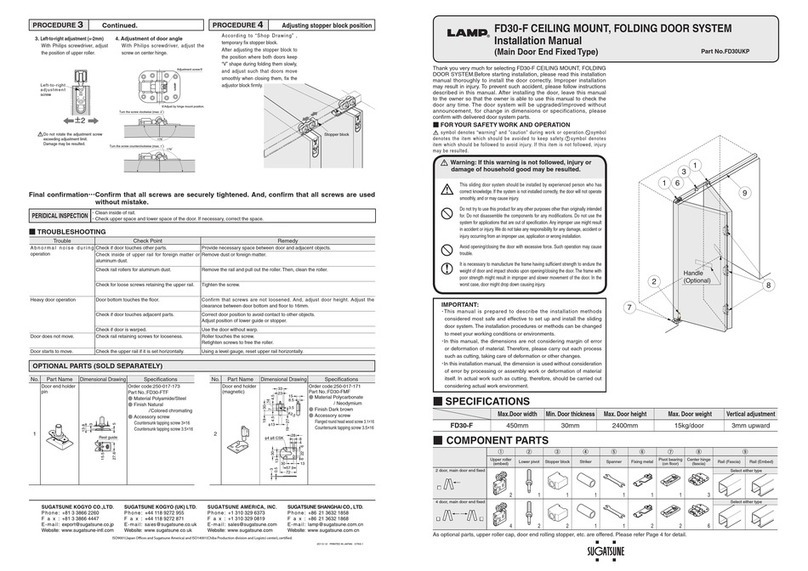
SUGATSUNE Lamp FD30-F User manual

SUGATSUNE

SUGATSUNE Lamp FD30-F User manual

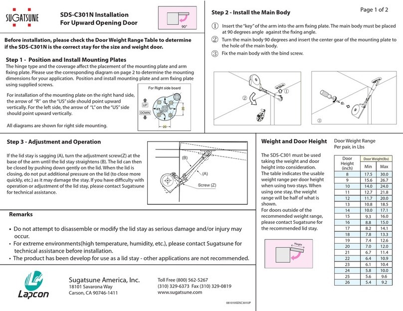
SUGATSUNE SDS-C301N User manual

SUGATSUNE

SUGATSUNE SDS-C301N User manual

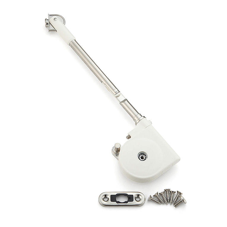
SUGATSUNE Aileron Lift-Assist User manual

SUGATSUNE

SUGATSUNE Aileron Lift-Assist User manual

SUGATSUNE LAMP FD80-H User manual

SUGATSUNE

SUGATSUNE LAMP FD80-H User manual

SUGATSUNE HES2S-140-A125 User manual

SUGATSUNE

SUGATSUNE HES2S-140-A125 User manual

SUGATSUNE LAMP MonoFlat FAD Series User manual

SUGATSUNE

SUGATSUNE LAMP MonoFlat FAD Series User manual

SUGATSUNE EB-90 User manual

SUGATSUNE

SUGATSUNE EB-90 User manual

SUGATSUNE Lapcon SDS-C301N-BLK User manual

SUGATSUNE

SUGATSUNE Lapcon SDS-C301N-BLK User manual

SUGATSUNE Zwei L ZL-2402 User manual

SUGATSUNE

SUGATSUNE Zwei L ZL-2402 User manual

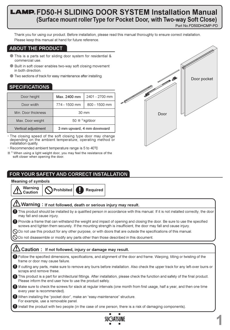
SUGATSUNE LAMP FD50-H User manual

SUGATSUNE

SUGATSUNE LAMP FD50-H User manual

SUGATSUNE LAMP LL-66S User manual

SUGATSUNE

SUGATSUNE LAMP LL-66S User manual

SUGATSUNE LAMP ALT-F User manual

SUGATSUNE

SUGATSUNE LAMP ALT-F User manual

SUGATSUNE LAMP LM-80 User manual

SUGATSUNE

SUGATSUNE LAMP LM-80 User manual

SUGATSUNE LAMP Lapcon SDS-210 User manual

SUGATSUNE

SUGATSUNE LAMP Lapcon SDS-210 User manual

Popular Door Opening System manuals by other brands

DITEC DAS107PLUS user manual

DITEC

DITEC DAS107PLUS user manual

CAB SUBWAY SB.25AC Operating instructions and spare parts catalogue

CAB

CAB SUBWAY SB.25AC Operating instructions and spare parts catalogue

TOPP M200 Instructions for installation and use

TOPP

TOPP M200 Instructions for installation and use

CAMDEN CM-550SK-V2 installation instructions

CAMDEN

CAMDEN CM-550SK-V2 installation instructions

JNF IN.81.203 Assembly

JNF

JNF IN.81.203 Assembly

Assa Abloy Corbin Russwin DC6210 Series installation instructions

Assa Abloy

Assa Abloy Corbin Russwin DC6210 Series installation instructions

Johnson Controls MC-303 PG+ Nstallation guide

Johnson Controls

Johnson Controls MC-303 PG+ Nstallation guide

ENFORCER SD-962AR-36G manual

ENFORCER

ENFORCER SD-962AR-36G manual

SANKI S-CON MINI SLIM Operating and service manual

SANKI

SANKI S-CON MINI SLIM Operating and service manual

Dorma RTS Series quick start guide

Dorma

Dorma RTS Series quick start guide

Dormakaba RTS88 installation instructions

Dormakaba

Dormakaba RTS88 installation instructions

Assa Abloy SARGENT 1130-HU Series installation instructions

Assa Abloy

Assa Abloy SARGENT 1130-HU Series installation instructions

CDVI VIRA20245048 installation manual

CDVI

CDVI VIRA20245048 installation manual

Entrematic AXK4 Series manual

Entrematic

Entrematic AXK4 Series manual

Abus PR1500 manual

Abus

Abus PR1500 manual

Entrematic Ditec VALLOKA installation manual

Entrematic

Entrematic Ditec VALLOKA installation manual

Assa Abloy Corbin Russwin PED159 installation instructions

Assa Abloy

Assa Abloy Corbin Russwin PED159 installation instructions

ADG Mover Installation and use manual

ADG

ADG Mover Installation and use manual

manuals.online logo
manuals.online logoBrands
  • About & Mission
  • Contact us
  • Privacy Policy
  • Terms and Conditions

Copyright 2025 Manuals.Online. All Rights Reserved.