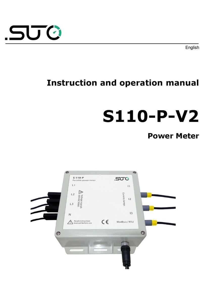
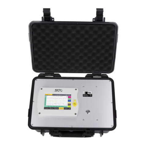
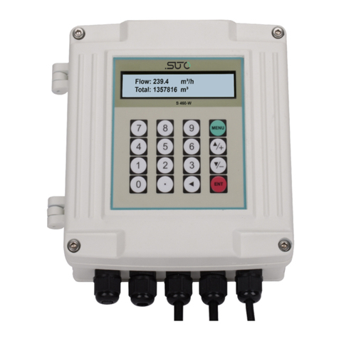
SUTO S110 Manual

English
Instruction and operation manual
S110
Power Meter

Dear Customer,
Thank you for choosing our product.
The operating instructions must be read in full and carefully observed
before starting up the device. The manufacturer cannot be held liable for
any damage which occurs as a result of non-observance or non-
compliance with this manual.
Should the device be tampered with in any manner other than a
procedure which is described and specified in the manual, the warranty
is cancelled and the manufacturer is exempt from liability.
The device is destined exclusively for the described application.
S TO offers no guarantee for the suitability for any other purpose. S TO
is also not liable for consequential damage resulting from the delivery,
capability or use of this device.
2 S110

Table of contents
1 Safety Instructions......................................................................4
2 Registered Trademarks................................................................5
3 Application.................................................................................6
4 Features....................................................................................6
5 Technical Data............................................................................6
5.1 General................................................................................6
5.2 Electrical Data.......................................................................7
5.3 Input Signals........................................................................7
5.4 Output Signals......................................................................7
5.5 Accuracy .............................................................................7
6 Dimensional Drawing (in mm).......................................................8
7 Determination of the Installation Point...........................................9
8 Installation ................................................................................9
8.1 Installation Requirements.......................................................9
8.2 Installation Procedure ...........................................................9
8.3 Voltage and Current Connection............................................10
8.3.1 3-Phase / 4-Wire Connection..........................................10
8.3.2 3-Phase / 3-Wire Connection..........................................10
8.3.3 1-Phase / 2-Wire Connection..........................................11
8.4 Electrical Connection............................................................11
8.4.1 Connection to S330 / S331.............................................12
8.4.2 Connection of the Rogowski Coils.....................................12
9 Signal Output...........................................................................14
9.1 Modbus Interface ................................................................14
9.2 Connect Modbus/RT Devices to a Master...............................15
9.2.1 Modbus/RT Cable Length..............................................15
9.2.2 Modbus/RT Wiring and Cable Type.................................15
9.2.3 Daisy-Chain using RS-485 Splitter...................................16
9.2.4 Topology of Modbus/RT Daisy-Chain...............................17
10 Optional Extra Accessories........................................................19
11 Maintenance...........................................................................19
12 Disposal or Waste....................................................................19
13 Appendix: Modbus Commands..................................................20
13.1 Command Request.............................................................20
13.2 Configure Meter.................................................................21
13.3 Command List...................................................................22
13.4 Modbus Register List..........................................................25
13.5 Harmonics Calculations.......................................................36
13.6 Power, Energy and Power Factor..........................................36
S110 3

1 Safety Instructions
Please check if this instruction manual matches with the
product type.
Please observe all notes and instructions indicated in this
manual. It contains essential information which have to be
observed before and during installation, operation and
maintenance. Therefore this instruction manual has to be read carefully
by the technician as well as by the responsible user / qualified personnel.
This instruction manual has to be available at the operation site of the
power meter at any time. In case of any obscurities or questions,
regarding this manual or the product, please contact the manufacturer.
WA NING!
Dangerous Voltage levels!
Any contact with energized parts of the product, may
lead to a electrical shock which can lead to serious
injuries or even death!
•Consider all regulations for electrical installations.
•The system must be disconnected from any power supply during
maintenance work.
•Any electrical work on the system is only allowed by authorized
qualified personal.
ATTENTION!
Permitted operating parameters!
Observe the permitted operating parameters, any
operation exceeding this parameters can lead to
malfunctions and may lead to damage on the
instrument or the system.
•Do not exceed the permitted operating parameters.
•Make sure the product is operated in its permitted limitations.
•Do not exceed or undercut the permitted storage and operation
temperature.
•The product should be maintained frequently, at least annually.
4 S110

1 Safety Instructions
General safety instructions
•It is not allowed to use the product in explosive areas.
•Please observe the national regulations before/during installation
and operation.
emarks
•It is not allowed to disassemble the product.
ATTENTION!
Measurement values can be affected by malfunction!
The product must be installed properly and
frequently maintained, otherwise it may lead to
wrong measurement values, which can lead to wrong
results.
Storage and transportation
•Make sure that the transportation temperature of device is
between -30°C ... +70°C.
•For transportation it is recommended to use the packaging which
comes with the device.
•Please make sure that the storage temperature of the device is
between -40°C ... +85°C.
•Avoid direct V and solar radiation during storage.
•For the storage the humidity has to be <90%, no condensation.
2 egistered Trademarks
S TO®
Registered trademark of S TO iTEC
MODB S®
Registered trademark of the Modbus Organization, Hopkinton, SA
HART®
Registered trademark of the HART Communication Foundation, Austin,
SA
PROFIB S®
Registered trademark of the PROFIB S ser Organization, Karlsruhe,
Germany
S110 5

3 Application
3 Application
The power meter is designed to measure the actual power consumption
in kW and accumulate the energy consumption in kWh of a 3-phase load.
Additionally other measured parameters such as current, voltage, cos phi
etc. are available as well.
4 Features
•Measures active and reactive power, frequency, voltage, currents,
power factor.
•Accumulates active energy [kWh].
•3-phase 3-wire, 3-phase 4-wire, 1-phase 2-wire measurement
•Modbus / RT output.
5 Technical Data
5.1 General
Parameters
(rms values)
Voltage of each phase and average voltage [V]
Current of each phase and average current [A]
Active Power [kW]
Reactive Power [kvar]
Apparent Power [kVA]
Energy (per phase and summery)
Power factors
Frequency [Hz]
Total Harmonic Distortion [%]
Nominal voltage range 100 V ... 500 V
Power range up to 2500 kW (depends on Rogowski coil)
Frequency range 50 / 60 Hz
Harmonic up to 52th
Sampling rate 8 k/sec
Available clamp sensors Rogowski coil 1 ... 100 A
10 ... 1000 A
30 ... 3000 A
Operating temperature -25 ... +55°C
6 S110

5 Technical Data
Storage temperature -40 ... +85°C
Protection class IP20 conforming to IEC 60629
Dimensions 145 mm x 40 mm x 90 mm (L X W X H)
Weight 210 g
5.2 Electrical Data
Power supply 24 VDC
5.3 Input Signals
Rogowski Coil 0 mV ... 333 mV
5.4 Output Signals
Modbus output See chapter 9.1
5.5 Accuracy
Voltage:
Current:
Power factor:
Frequency:
Active/Apparent Power:
Reactive Power:
Active Energy:
Reactive Energy:
0.2% (100 ... 500 V)
0.5% (1% ... 120% of range)
0.005 from 10 ... 120%
0.01% from 45 ... 65 Hz
IEC62053-22 Class 0.5
IEC62053-21 Class 2
IEC62053-22 Class 0.5s
IEC62053-21 Class 2
S110 7

7 Determination of the Installation oint
7 Determination of the Installation Point
It is possible to install the power meter directly into the connection box
on the compressor or into the connection cabinet where the power
supply for the compressor is coming from.
8 Installation
Please make sure that all components listed below are included in your
package.
Qty Description Item No.
1 Power meter D554 0130
3 Rogowski coils S554 0140 or S554 0141 or S554 0142
1 Instruction manual No P / N
8.1 Installation equirements
ATTENTION!
Wrong measurement is possible, if the device is not
installed correctly.
•The device is for indoor use only! At an outdoor installation, the
device must be protected from solar radiation and rain.
•It is strongly recommend not to install S110 in wet environment.
8.2 Installation Procedure
Installation of the S110 hat rail mountable
The S110 is hat rail mountable and recommended to be installed either
in the power distribution cabinet or in the connection box of the
compressor.
S110 9

8 Installation
8.3.3 1-Phase / 2-Wire Connection
8.4 Electrical Connection
The power meter S110 can be connected to the S330 / 331. For the
electrical installation please observe the following instructions.
Above is the connection diagram of the S110
ATTENTION!
Do not connect any conventional coil to the ogowski
Coil inputs. Otherwise it will permanently damage
the device!
S110 11

8 Installation
8.4.1 Connection to S330 / S331
S330 / S331 S110 Legend to pin assignment
Terminal Pin Signal Pin Signal + Vb Negative supply voltage
A or B 3 + Vb 26 + 24 V - Vb Positive supply voltage
2 - Vb 25 0 V + D Modbus data +
4 + D 18 + D - D Modbus data -
5 - D 19 - D GND Ground for Modbus
6 GND 20 GND
8.4.2 Connection of the ogowski Coils
Please observe the following steps to connect the coil.
12 S110

8 Installation
1. Pay attention to the current direction, it is indicated with a
direction arrow on the housing.
2. The color code of the cable has 2 versions, connect the + cable
and-cable to the current signal input of S110-V2. Please refer to
section 8.3 for connection details.
Order no. S554 0142 S554 0140 S554 0141
Coil diameter (mm) 16 100 150
S110 13

9 Signal Output
9 Signal Output
The S110 has a Modbus/RT output to the S330/S331.
9.1 Modbus Interface
The default settings of the Modbus communication interface are as
follows:
Mode : RT
Baud rate : 19200
Device address : Last two digits of serial number
Framing / parity / stop bit : 8, N, 1
Response timeout : 1 second
Response delay : 0 ms
Inter-frame spacing : 7 char
esponse message that the device returns to the master:
•Function code: 03
The information for the byte order is shown in the table below:
Byte
Order
Sequence Data
Type
1st 2nd 3rd 4th
1-0-3-2 Byte 1
(MMMMMMMM*)
Byte 0
(MMMMMMMM *)
Byte 3
(SEEEEEEE)
Byte 2
(EMMMMMMM *) FLOAT
1-0-3-2 Byte 1 Byte 0
LSB
Byte 3
MSB Byte 2 INT32
INT32
1-0 Byte 1
MSB
Byte 0
LSB --- --- INT16
INT16
1-0 Byte 1
XXX *
Byte 0
DATA --- --- INT8
INT8
* S: Sign, E: Exponent, M: Mantissa, XXX: no value
Notes:
•The settings of the Modbus communication can be changed by the
Modbus software.
•For more information on the Modbus commands, see chapter 13
Appendix: Modbus Commands.
14 S110

9 Signal Output
9.2 Connect Modbus/ TU Devices to a Master
Sensors and devices with a Modbus/RT output can be connected to a
Modbus master device. This master can be either S TO displays and
gateways or any third-party Modbus/RT master.
See below specifications of the Modbus/RT connections.
9.2.1 Modbus/ TU Cable Length
A Modbus/RT bus line has limitations which shall not be exceeded,
otherwise the communication might not be stable.
•The maximum total bus length must not exceed 1200 m.
•The stub length to each node must not exceed 30 cm.
See the picture below for details.
9.2.2 Modbus/ TU Wiring and Cable Type
To ensure a stable communication a twisted-pair bus cable must be
chosen to set up the Modbus/RT communication.
•Bus-cable specifications must follow the EIA485 Standard, must be
twisted pair and shielded, for example 2 x 2 x 0.22 mm2, Li-2YCY
(A553 0123).
S110 15

9 Signal Output
•The shield must be connected at one end to the master GND
connection.
•At the end of the bus, a 120 Ohm resistor should be placed a
termination resistor.
See the below picture for details.
9.2.3 Daisy-Chain using S-485 Splitter
S TO devices with M12 connectors can be easily connected in a
Modbus/RT daisy-chain using a M12 RS-485 splitter (A554 3310).
Furthermore this allows to easily place the M12 termination resistor
(C219 0055) at the last splitter in the bus-chain.
See below example for reference.
16 S110

9 Signal Output
Connect Modbus/RT slaves with M12 connectors to a daisy-chain using
M12 RS-485 splitters.
9.2.4 Topology of Modbus/ TU Daisy-Chain
The recommended bus topology is to connect devices as a daisy-chain.
Other connection topologies are not recommended and should be
avoided. Make sure that at the end of the bus line, the termination
resistor of 120 Ohm is placed to avoid interferences.
Recommended connection of Modbus/RT salves in a daisy-chain
topology.
S110 17

10 Optional Extra Accessories
The following extra accessories are available:
•Rogowski coil, 100 A, 16 mm diameter, 1.8 m cable, open ends.
•Rogowski coil, 1000 A, 100 mm diameter, 1.8 m cable, open ends.
•Rogowski coil, 3000 A, 150 mm diameter, 1.8 m cable, open ends.
11 Maintenance
ATTENTION!
Do not use isopropyl alcohol to clean the power
meter!
12 Disposal or Waste
Electronic devices are recyclable material and do not belong
in the household waste.
The sensor, the accessories and its packings must be
disposed according to your local statutory requirements.
The dispose can also be carried by the manufacturer of the
product, for this please contact the manufacturer.
S110 19

13 Appendix: Modbus Commands
13.1 Command equest
Slave Address Function Code Command
Block
C C
8-Bit 8-Bit N×8-Bit 16-Bit Checking
Functional code
Functional code tells what function addressed terminal equipment can
execute. The following table lists the functional code that used by this
instrument, as well as their significance and function.
Function Code Function Name Behavior
Decimal Hexadecimal
3 03H Read Holding
Registers
Read present HEX from one or
more registers.
16 10H Write Multiple
Registers
Write present HEX on multiple
registers.
egister table
Register tables have the following columns:
Register
Alias
Register
Address
Action
R/WC Size Type nits Description
egister Alias The meaning of the register
egister
Address
Modbus address of register encoded in the Modbus frame, in
decimal (dec)
Action /WC The read/write by command register
Size The data size in Int16
Type The encoding data type
Units The unit of the register value
ange The permitted values for this variable, usually a subset of
what the format allows
Description Provides information about the register and the values that
apply
20 S110
Table of contents
Other SUTO Measuring Instrument manuals
Popular Measuring Instrument manuals by other brands

Extech Instruments
Extech Instruments HD450-NIST user guide

BANTE inststruments
BANTE inststruments 210 instruction manual

Azbil
Azbil MagneW Plus+ Series user manual

ThermoWorks
ThermoWorks BlueTherm IR operating instructions

Siemens
Siemens SITRANS L APPLICATION EXAMPLES

Dickey-John
Dickey-John C-2000 manual