SUTO S551 Manual

English
Instruction and operation manual
S551
Compressed air analyzer

Dear Customer,
Thank you for choosing our product.
The operating instructions must be read in full and carefully observed
before starting up the device. The manufacturer cannot be held liable
for any damage which occurs as a result of non-observance or non-
compliance with this manual.
Should the device be tampered with in any manner other than a
procedure which is described and specified in the manual, the warranty
is cancelled and the manufacturer is e empt from liability.
The device is designed e clusively for the described application.
SUTO offers no guarantee for the suitability for any other purpose.
SUTO is also not liable for consequential damage resulting from the
delivery, capability or use of this device.
2 S551

Table of contents
1. Safety instructions.......................................................................5
2. Application.................................................................................7
3. Features.....................................................................................7
4. Technical data.............................................................................8
4.1 General.................................................................................8
4.2 Electrical data........................................................................8
4.3 Input-signals..........................................................................8
4.4 Output-signals.......................................................................8
5. Installation ................................................................................9
5.1 Installation Requirements........................................................9
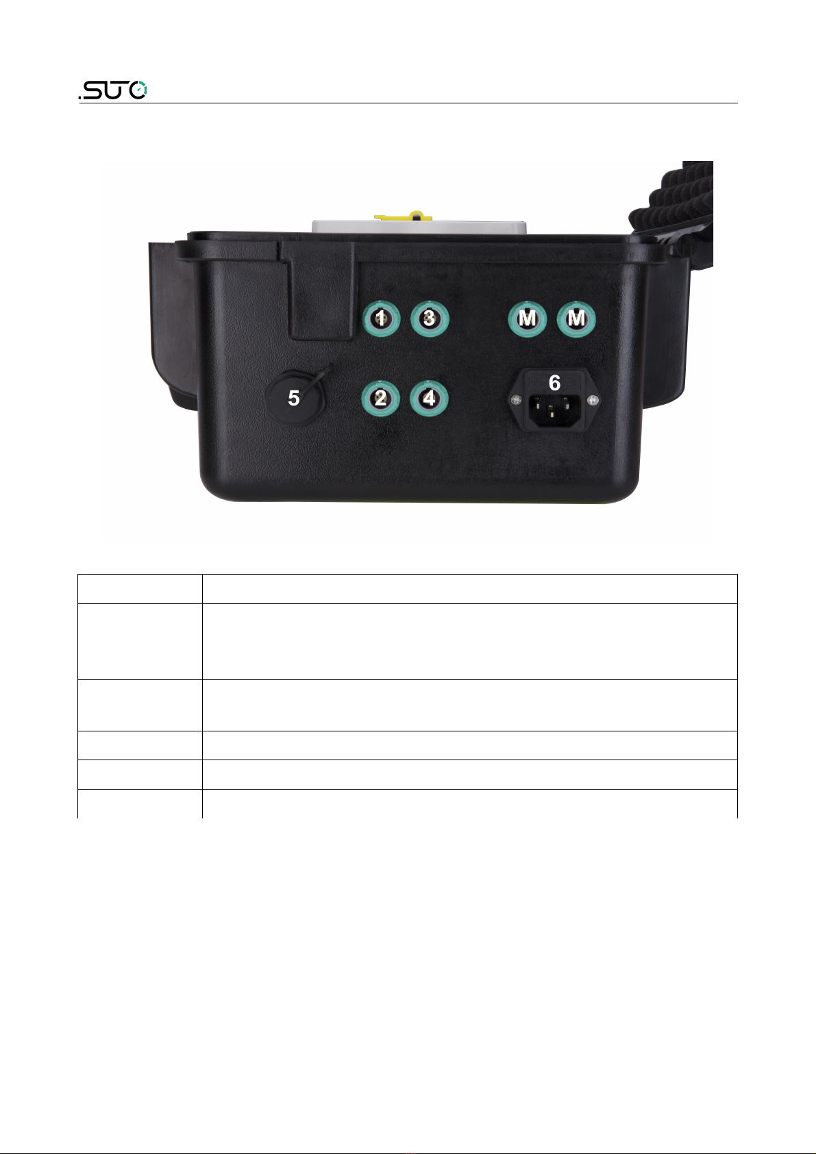
5.2 Connectors on the case.........................................................10
5.3 Electrical connection..............................................................13
5.3.1 Sensors powered by S551 ...............................................13
5.3.2 Electrical connection........................................................14
6. Configuration ...........................................................................15
7. Operation ................................................................................15
7.1 Value screen........................................................................16
7.2 Main menu ..........................................................................17
7.3 Icons in the status bar ..........................................................18
7.4 Graphic screen.....................................................................19
7.5 Sensor setting .....................................................................19
7.5.1 Dew point setting ...........................................................20
7.5.2 Flow sensor setting ........................................................21
7.5.3 Oil vapor sensor setting ..................................................23
7.5.4 Analog input setting .......................................................24
7.5.5 Power meter S110-P setting.............................................25
7.5.6 Analog e tension module.................................................25
7.5.7 Laser particle counter S130..............................................25
7.5.8 Ultrasound liquid flow meter S460.....................................25
7.6 Logger.................................................................................26
7.7 Files....................................................................................27
7.8 Service info. ........................................................................27
7.9 System settings....................................................................28
7.10 Communication...................................................................29
7.10.1 IIoT.............................................................................29
7.10.2 Field-bus Ethernet.........................................................30
8. Application e ample...................................................................31
9. Signal inputs ............................................................................32
9.1 Digital inputs........................................................................32
9.2 Analog input ........................................................................32
10. Signal outputs.........................................................................32
S551 3

11. Optional accessories.................................................................32
12. Calibration..............................................................................33
13. Maintenance............................................................................33
15. Disposal or waste.....................................................................33
15. Warranty................................................................................33
4 S551

1. Safety instructions
Please check if this instruction manual accords to the
product type.
Please observe all notes and instructions indicated in this
manual. It contains essential information which must be
observed before and during installation, operation and
maintenance. Therefore this instruction manual must be read carefully
by the technician as well as by the responsible user / qualified
personnel.
This instruction manual must be available at the operation site of the
compressed air analyzer at any time. In case of any obscurities or
questions, regarding this manual or the product, please contact the
manufacturer.
WA NING!
Compressed air!
Any contact with quickly escaping air or bursting
parts of the compressed air system can lead to
serious injuries or even death!
•Do not e ceed the ma imum permitted pressure range (see
sensors label).
•Only use pressure tight installation material.
•Avoid that persons get hit by escaping air or bursting parts of the
instrument.
•The system must be pressureless during maintenance work.
WA NING!
Voltage used for supply!
Any contact with energized parts of the product, may
lead to a electrical shock which can lead to serious
injuries or even death!
•Consider all regulations for electrical installations.
•The system must be disconnected from any power supply during
maintenance work.
•Any electrical work on the system is only allowed by authorized
qualified personal.
S551 5

1. Safety instructions
ATTENTION!
Permitted operating parameters!
Observe the permitted operating parameters, any
operation exceeding this parameters can lead to
malfunctions and may lead to damage on the
instrument or the system.
•Do not e ceed the permitted operating parameters.
•Make sure the product is operated in its permitted limitations.
•Do not e ceed or undercut the permitted storage and operation
temperature and pressure.
•The product should be maintained and calibrated frequently, at
least annually.
General safety instructions
•It is not allowed to use the product in e plosive areas.
•Please observe the national regulations before/during installation
and operation.
emarks
•It is not allowed to disassemble the product.
ATTENTION!
Measurement values can be affected by malfunction!
The product must be installed properly and
frequently maintained, otherwise it may lead to
wrong measurement values, which can lead to
wrong results.
Storage and transportation
•Make sure that the transportation temperature of the device is
between -20 ... +50°C.
•For transportation it is recommended to use the packaging which
comes with the device.
•Please make sure that the storage temperature of the device is
between -20 ... +50°C.
6 S551

1. Safety instructions
•Avoid direct UV and solar radiation during storage.
•For the storage the humidity must be <90%, no condensation.
2. Application
The S551 is a compressed air analyzer that is designed to display and
record all relevant parameters of compressed air and gases within the
permissible operating parameters. These parameters can be found in
the technical data section.
The S551 can analyze the flow, dew point, pressure, temperature,
power consumption, and many more.
The S551 compressed air analyzer is mainly used in compressed air
systems in industrial environment. The S551 is not developed to be
used in e plosive areas. For the use in e plosive areas please contact
the manufacturer.
3. Features
•Supports various types of sensors for all required measurement
tasks (air flow, air consumption, power consumption, pressure,
temperature and many more).
•Supports up to 24 inputs through e tension modules and Modbus.
•Several loggers can be combined. No need to have long cables
from the sensor to the logger.
•Supports third-party sensors.
•IP65 casing provides robust protection in the industrial
environment.
•High-resolution 5” colour touch screen interface.
•With the battery-backed power, unaffected from power glitches
and failure.
•Full software packages are included:
◦S4A for basic analysis
◦CAA for compressed air audit analysis
S551 7

4. Technical data
4. Technical data
4.1 General
Data logger 4 GB, up to 100 million values
Operating temperature 0 ... _50°C
Housing material PC + ABS
Protection class IP65 (only if the suitcase lid is closed and
locked)
Dimensions 365 mm 270 mm 169 mm
Display 5” high resolution graphic display, 800 480
pi els with touch interface
Weight 4 kg
4.2 Electrical data
Power supply 100 ... 240 VAC / 50 VA, 47-60 Hz
Internal battery Rechargeable for up to 8 hours operation.
Charging time ca. 3 hours
4.3 Input-signals
Analog input 0 ... 1 V, 0 ... 10 V, 0 ... 20 mA, 4 ... 20 mA
Digital input 2 SDI Sensors
16 RS-485 Modbus RTU Sensors
4.4 Output-signals
Communication Interface Ethernet, USB
8 S551

5. Installation
5. Installation
Please make sure that all components listed below are included in your
package.
Qty Description Item No.
1 S551-P4 / S551-P6 P560 5100 / P560 5101
1 USB cable A553 0130
1 Instruction manual No P/N
1 Calibration certificate No P/N
5.1 Installation equirements
ATTENTION!
Wrong measurement is possible if the device is not
installed correctly.
•The device is for indoor use only! At an outdoor installation, the
device must be protected from solar radiation and rain.
•It is strongly recommended you not install S551 permanently in
wet environment such as the place right after a compressor outlet.
S551 9

5. Installation
5.2 Connectors on the case
Connector Description
1, 2 Connectors for SDI sensors, which include:
•Flow sensors: S401/421, S450/452, S430
•Dew point sensors: S220, S212, S215, S217, S201
3, 4 Connectors for process signal sensors (such as analog
signal sensors and pulse sensors)
M, M Connectors for Modbus sensors and devices
5 Ethernet port
6 Main supply
10 S551

5. Installation
To connect different sensors to the S551, refer to the following table for
the designed terminals.
Signal
Connector
1/2
Signal
Connector
M/M
Signal Colour
Connector
3/4
Connector
3/4
Dew point/
flow sensor
Modbus /
RTU
Pulse
active
Pulse
passive
SDI N/A
+I /
Pulse brown
-V -V 20 mA white
+V +V +V blue
N/A +D -V black
N/A -D +S grey
Signal Colour
Connector
3/4
Connector
3/4
Connector
3/4
Connector
3/4
Connector
3/4
Ampere
sensor
Pressure 1V ... 10V 20 mA
active
20 mA
passive
+I /
Pulse brown
20 mA white
+V blue
-V black
+S grey
S551 11

5. Installation
Legend to pin assignment
SDI Digital signal (internal use)
-V Negative supply voltage
+V Positive supply voltage
+I Active 4 ... 20 mA signal
+D Modbus Data +
-D Modbus Data -
+S Positive Voltage Input
NA Not Applicable
Pins for the ODU connector
Connection pins
(view from the clamping side)
12 S551

5. Installation
5.3 Electrical connection
With the casing, the S551 does not need a costly installation.
5.3.1 Sensors powered by S551
The S551 supplies 24 VDC and totally 20 W to the connected sensors.
Please make sure that power consumption of all sensors connected to
the S551 do not e ceed this power limit.
Refer to the table below to calculate the power consumption.
Sensor Power [W]
Flow meter S401 / 421 3.0
Flow meter S415 / 418 3.0
Flow meter S430 3.0
Flow meter S450 / 452 5.0
Flow meter S400 / 420 3.0
Dew point sensor S230 / 231 1.2
Dew point sensors S220, S212, S215 1.0
Pressure sensor 0.5
Analog input e tension (8-Channel) 1.3
Power meter S110-P and S110-P-V2 1.0
Current sensor 0.5
Ultrasonic flow meter controller S460-P 1.5
Oil vapor sensor S120-P 10.0
Laser particle counter S130 10.0
S551 13

5. Installation
5.3.2 Electrical connection
Before powering on the S551, please connect all sensors with the S551.
•For SDI sensors, connect them to the S551 through connectors 1
and 2 on the case.
•For Modbus sensors, connect them to the S551 through
connectors M on the case.
•For analog signal sensors such as 0 ... 20 mA, 4 ... 20 mA, 0 ... 1
V, 0 ... 10 V and pulse signal sensors, you can connect them to the
S551 through connectors 3 and 4 according to the pin assignment
shown in section 5.2 Connectors on the case.
Notes:
•The S551 can automatically detect SDI and Modbus-based sensors
from SUTO, which include flow sensors, dew point sensors, and
e tension modules (such as power meters, Ultrasonic flow meters,
and analog e tension modules).
•The S551 cannot automatically detect process signal-based
sensors. You must manually add the appropriate sensor types by
using the corresponding S551 configuration menu. For details
please refer to section 7.5.4 Analog input setting .
14 S551

6. Configuration
6. Configuration
The S551 is delivered with specific customized settings according to the
order. All settings are stored in the S551. To change e -work settings,
refer section 7.5 Sensor setting .
7. Operation
The On / Off switch on the S551 panel enables you to do the following:
•To view the remaining battery capacity and the charging status,
shortly press the button.
•To start up the device, keep pressing the button for 2 seconds.
•To power off the device, keep the button pressed for 2 seconds at
least.
When the S551 starts up it will
display the start up screen for a
few seconds. During this time the
sensor connections are established
and a few other initialisation tasks
are performed.
S551 15

7. Operation
7.1 Value screen
The S551 automatically detects and communicates with the connected
sensors and starts to display measurement values in real time.
The function of quick buttons or icon on the bottom bar are as follows:
•Graphic:To switch to the graphic view.
•Value: To switch to the value view.
•Menu: To access the main menu for detailed settings.
•Up and Down arrows: To scroll up and down pages to view
measured data.
•The camera icon: To take a screenshot.
16 S551

7. Operation
7.2 Main menu
The main menu enables you view and configure settings of the S551
and the connected sensors.
Quick buttons
Status bar
Function
buttons
The main menu consists of the following sub-menus:
Sensor settings To change settings related to the connected sensors.
Logger To view and change the S551 data logger settings.
Files To view and manage all recorded files and view the
memory status.
Service info To view the service information in case of a service
issue.
System setting To perform system-level settings.
Communication To perform communication settings based on the
protocol used, such as Modbus master, field bus RS-
485, Ethernet, or IIoT.
S551 17

7. Operation
7.4 Graphic screen
7.5 Sensor setting
The sensor setting menu enables you to configure specific settings for
the sensors connected to S551.
After you select “Sensor setting”, the screen shows which kind of
sensors are configurable. You can change settings individually for each
sensor by selecting a sensor as needed.
emarks
The S551 can automatically detect the connected sensors manufactured
by SUTO. The standard settings of these sensors are completed e -
works.
S551 19

7. Operation
7.5.1 Dew point setting
Analog output Select the physical moisture unit and set scaling of
analog output:
Whenever you change the moisture unit, it is
recommended to adjust the scaling of the analog
output. The S551 will recommend a standard scaling.
The scaling is used to e press the moisture through a
4 ... 20 mA signal, which than can be transferred to a
PLC or SCADA system.
Set the moisture unit: ppm (V), g/m3, mg/m3 and the
atmospheric dew point requires to enter a reference
pressure.
Dew point
cali.
Dew point sensors can be adjusted at one point
according to a reference value. We recommend you
perform this calibration only below -40 °C dew point
and by using a reliable reference.
Pressure
calibration
Some dew point sensors have integrated pressure
sensors. which can be calibrated here.
Modbus
setting
Some sensors have the Modbus interface.
Communication parameters can be set here.
More settings •Filters can be activated to dampen the output
signal.
•Auto cali setting allows the activation of an auto
calibration function.
20 S551
Other manuals for S551
2
Table of contents
Other SUTO Measuring Instrument manuals
Popular Measuring Instrument manuals by other brands

Omega
Omega DP25B-E user guide

BEKA
BEKA BA488CF-P PROFIBUS PA manual

Hanna Instruments
Hanna Instruments HI-96730 instruction manual

Olympus
Olympus USPM-RUIII Series Hardware operation manual

TSI Instruments
TSI Instruments VelociCalc Plus 8384 Operation and service manual

PCB Piezotronics
PCB Piezotronics J351B31 Installation and operating manual

BUILD TEST SOLUTIONS
BUILD TEST SOLUTIONS BTS-Pulse 2.0 Instruction Manual and Safety Guidelines

Burster
Burster RESISTOMAT 2 11 Series manual

TESTO
TESTO 512 instruction manual

Teledyne
Teledyne T3SP Series Operator's manual

IFM
IFM SM4x00 operating instructions

Chauvin Arnoux
Chauvin Arnoux AEMC Instruments MR417 user manual