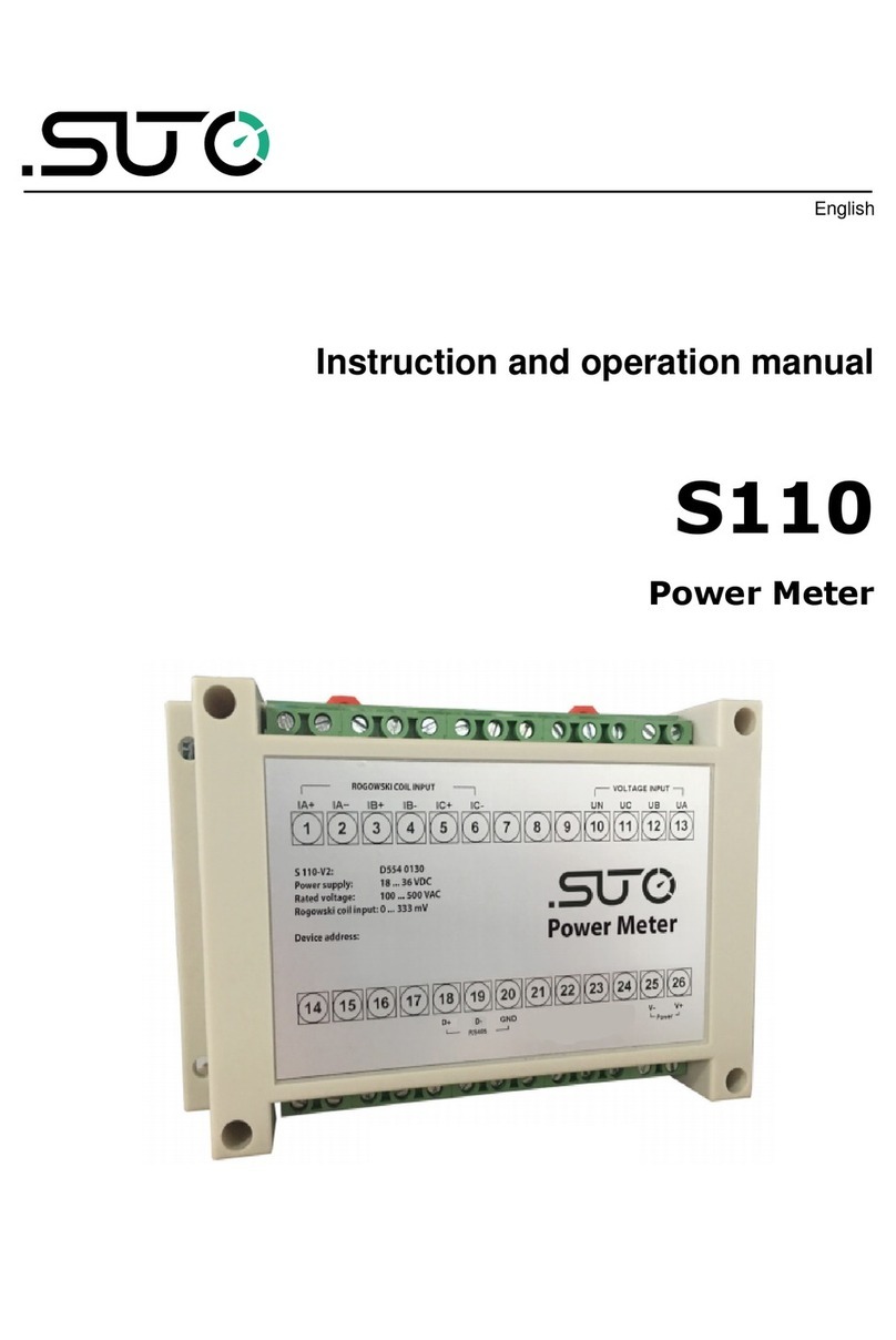
SUTO S110-P-V2 Manual

English
Instruction and operation manual
S110-P-V2
Power Meter

Dear Customer,
Thank you for choosing our product.
The operating instructions must be read in full and carefully observed
before starting up the device. The manufacturer cannot be held liable
for any damage which occurs as a result of non-observance or non-
compliance with this manual.
Should the device be tampered with in any manner other than a
procedure which is described and specified in the manual, the warranty
is cancelled and the manufacturer is exempt from liability.
The device is destined exclusively for the described application.
S TO offers no guarantee for the suitability for any other purpose.
S TO is also not liable for consequential damage resulting from the
delivery, capability or use of this device.
2 S110-P-V2

1 Safety instructions
Table of contents
1 Safety instructions.......................................................................4
2 Registered trademarks.................................................................5
3 Application.................................................................................6
4 Features.....................................................................................6
5 Technical data.............................................................................6
5.1 General................................................................................6
5.2 Electrical data.......................................................................7
5.3 Input-signals.........................................................................7
5.4 Accuracy .............................................................................7
6 Dimensional drawing (in mm).......................................................8
7 Installation ................................................................................9
7.1 Voltage and current connection...............................................9
7.1.1 3-phase / 4-wire connection..............................................9
7.1.2 3-phase / 3-wire connection............................................10
7.1.3 1-phase / 2-wire connection............................................10
7.2 Electrical connection.............................................................11
7.2.1 Connection to S551 .......................................................11
7.2.2 Connection to the Rogowski coils......................................13
7.2.3 Connection to the Voltage leads.......................................14
8 Optional extra accessories..........................................................15
8.1 Extra accessories for S110-P.................................................15
9 Maintenance.............................................................................15
10 Disposal or waste.....................................................................15
S110-P-V2 3

1 Safety instructions
Please check if this instruction manual accords to the
product type
Please observe all notes and instructions indicated in this
manual. It contains essential information which have to be
observed before and during installation, operation and
maintenance. Therefore this instruction manual has to be read carefully
by the technician as well as by the responsible user / qualified
personnel.
This instruction manual has to be available at the operation site of the
power meter at any time. In case of any obscurities or questions,
regarding this manual or the product, please contact the manufacturer.
WARNING!
Dangerous Voltage levels!
Any contact with energized parts of the product, may
lead to an electrical shock which can lead to serious
injuries or even death!
•Consider all regulations for electrical installations.
•The system must be disconnected from any power supply during
maintenance work.
•Any electrical work on the system is only allowed by authorized
qualified personal.
ATTENTION!
Permitted operating parameters!
Observe the permitted operating parameters, any
operation exceeding this parameters can lead to
malfunctions and may lead to damage on the
instrument or the system
•Do not exceed the permitted operating parameters.
•Make sure the product is operated in its permitted limitations.
•Do not exceed or undercut the permitted storage and operation
temperature.
•The product should be maintained frequently, at least annually.
4 S110-P-V2

1 Safety instructions
General safety instructions
•It is not allowed to use the product in explosive areas.
•Please observe the national regulations before/during installation
and operation.
Remarks
•It is not allowed to disassemble the product.
ATTENTION!
Measurement values can be affected by malfunction!
The product must be installed properly and
frequently maintained, otherwise it may lead to
wrong measurement values, which can lead to
wrong results
Storage and transportation
•Make sure that the transportation temperature of device is
between -30 ... +70 °C.
•For transportation it is recommended to use the packaging which
comes with the device.
•Please make sure that the storage temperature of the device is
between -40 ... +85 °C.
•Avoid direct V and solar radiation during storage.
•For the storage the humidity has to be <90%, no condensation.
2 Registered trademarks
S TO®
Registered trademark of S TO iTEC
MODB S®
Registered trademark of the Modbus Organization, Hopkinton, SA
HART®
Registered trademark of the HART Communication Foundation, Austin,
SA
PROFIB S®
Registered trademark of the PROFIB S ser Organization, Karlsruhe,
Germany
S110-P-V2 5

3 Application
3 Application
The power meter is designed to measures the actual power
consumption in kW and accumulates the energy consumption in kWh of
a 3-phase load. Additionally other measured parameters such as
current, voltage, cos phi etc. are available as well.
4 Features
•Measures active and reactive power, frequency, voltage, currents,
power factor.
•Accumulates active energy [kWh].
•3 phase 3 wire, 3 phase 4 wire, 1 phase 2 wire measurement
•Modbus / RT output to S551.
5 Technical data
5 1 General
Parameters
(rms values)
Voltage of each phase and average voltage [V]
Current of each phase and average current [A]
Active Power [kW]
Reactive Power [kvar]
Apparent Power [kVA]
Energy (per phase and summery)
Power factors
Frequency [Hz]
Nominal voltage range 100 ... 500 VAC
Power range up to 2500 kW (depends on Rogowski coil)
Frequency range 50 / 60 Hz
Sampling rate 8 k/sec
Available clamp sensors Rogowski coil 1 ... 100 A
10 ... 1000 A
30 ... 3000 A
Operating temperature -25 ... +55°C
Storage temperature -40 ... +85°C
6 S110-P-V2

5 Technical data
Protection class IP 20
Dimensions 177 mm x 60 mm x 203 mm (L X W X H)
Weight 800 g
5 2 Electrical data
Power supply 24 VDC
5 3 Input-signals
Rogowski Coil 0 mV ... 333 mV
5 4 Accuracy
Voltage
Current
Power Factor
Frequency
Active/Apparent Power
Reactive Power
Active Energy
Reactive Energy
0.2 % (100 ... 500 V)
0.5 % (1% ... 120% of rang)
0.005 from 10 ... 120 %
0.01 % from 45 ... 65 Hz
IEC62053-22 Class 0.5
IEC62053-21 Class 2
IEC62053-22 Class 0.5 s
IEC62053-21 Class 2
S110-P-V2 7

7 nstallation
7 Installation
Please make sure that all components listed below are included in your
package.
Qty Description Item No
1 Power meter S110-P P554 0134
3 Rogowski coils 1000A = S551 0160
3000A = S554 0161
100A = S554 0162
4 Test leads No P/N
4 Test clips No P/N
1 5 m cable with connector to S551. A553 0111
1 Instruction manual No P/N
7 1 Voltage and current connection
7 1 1 3-phase / 4-wire connection
S110-P-V2 9

7 nstallation
7 2 Electrical connection
The portable power meter S110-P is connected to the portable data
logger S551. For the electrical installation please observe the following
instructions.
Voltage leads
connection
with 4 mm
plugs
Coil
connection
with 2 pole
round
connector in
yellow.
Connection to S551 via Modbus / RT .
7 2 1 Connection to S551
1. Connect the S110-P with the S551 via Modbus port.
2. Power on S551 and then the S110-P will be detected
automatically.
3. Press the “Menu” button on the interface of S551 and select the
sensor type of clamp current sensor. For this please have a look at
the picture below.
4. Press Save when you have changed the settings.
5. go back to "Home”
S110-P-V2 11

7 nstallation
Coils for S110-P:
Arrow indication on the
grey plastics for the
current direction!
Typical connection for the S110-P:
7 2 3 Connection to the Voltage leads
For S110-P connect the voltage leads (L1, L2, L3 and N) to the 3 phase
conductors. Connect N if a 4-wire connection is required.
14 S110-P-V2

8 Optional extra accessories
For the particular type the following extra accessories are available:
•Transport case S551 for sensors and cables.
8 1 Extra accessories for S110-P
•Rogowski coil, 1000 A, 100 mm diameter, 1.8 m cable, connector
to S110-P.
•Rogowski coil, 3000 A, 150 mm diameter, 1.8 m cable, connector
to S110-P.
•Rogowski coil, 100 A, 16 mm diameter, 1.8 m cable, connector to
S110-P.
9 Maintenance
To clean the power meter it is recommended to use moist cloth only.
ATTENTION!
Do not use isopropyl alcohol to clean the power
meter!
10 Disposal or waste
Electronic devices are recyclable material and do not
belong in the household waste.
The sensor, the accessories and its packings must be
disposed according to your local statutory requirements.
The dispose can also be carried by the manufacturer of the
product, for this please contact the manufacturer.
S110-P-V2 15

S TO iTEC GmbH
Grißheimer Weg 21
D-79423 Heitersheim
Germany
S TO iTEC (ASIA) Co., Ltd.
Room 10, 6/F, Block B, Cambridge Plaza
188 San Wan Road, Sheung Shui, N.T.
Hong Kong
Tel: +49 (0) 7634 50488 00
Fax: +49 (0) 7634 50488 19
Email: [email protected]
Website: http://www.suto-itec.com
Tel: +852 2328 9782
Fax: +852 2671 3863
Email: [email protected]
Website: http://www.suto-itec.com
All rights reserved © Modifications and errors reserved
S110-P-V2_im_en_2022-1
16 S110-P-V2
This manual suits for next models
2
Table of contents
Other SUTO Measuring Instrument manuals