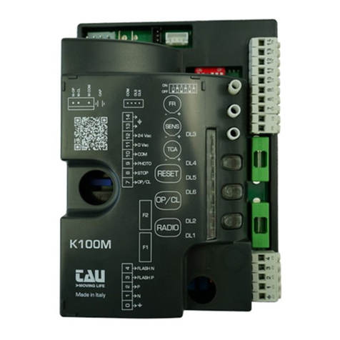
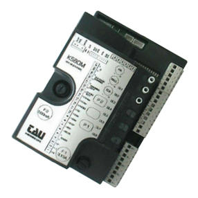
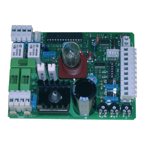
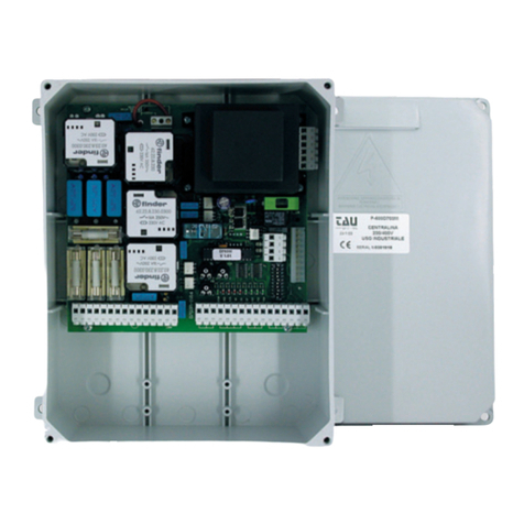
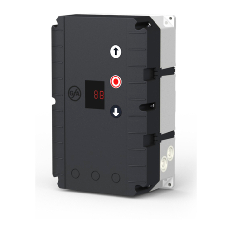
tau K100M User manual

INSTALLATION GUIDE
WARNING!
Attention: This product may only be installed from professional installers. Only qualied and trained electricians may
connect, programme and service the controls.
No information given in this manual can be considered as being of interest to end users.
This manual is enclosed with control unit K100M and may therefore not be used for dierent products!
Important information:
Disconnect electric power to the system before making maintenance, repairs or removing covers
The K100M control unit has been designed to control a electromechanical sliding door operator.
Any other use is considered improper and is consequently forbidden by current laws.
Read all instructions carefully and completely before attempting to install and use this automatic gate operator!
INSTALLATION
Make sure the gate has been properly installed and slides freely in both directions. Repair or replace all worn or damaged
gate hardware prior to installation. A freely moving gate will require less force to operate and will enhance the performance
of the operator and safety devices used with the system.
Also check that the gate operator assembly has been installed according to the instructions.
WARNING: The automatic gate operator must be grounded - All Federal, State and local safety codes must be observed.
ATTENTION:
- do not use solid wire, use only multi threaded wire
- do not reuse pre-existing electric wire.
IF THE ABOVE INSTRUCTIONS ARE NOT FOLLOWED THE “MANUFACTURER” SHALL IN NO EVENT BE LIABLE FOR DIRECT, INDI-
RECT, INCIDENTAL, SPECIAL OR CONSEQUENTIAL DAMAGES OR LOSS OF PROFITS WHETHER BASED IN CONTRACT TORT OR
ANY OTHER LEGAL THEORY DURING THE COURSE OF THE WARRANTY OR AT ANY TIME THEREAFTER.
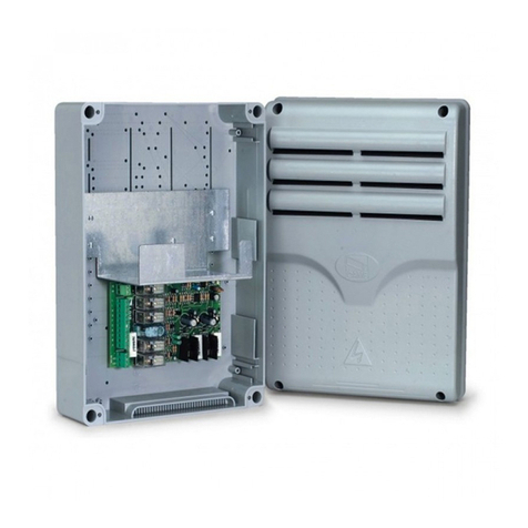
CONTROL PANEL FOR ONE 230 V AC MOTOR
MICROPROCESSOR-CONTROLLED LOGIC
STATUS LEDS
LINE FUSE
BUILT-IN FLASHING LIGHT CIRCUIT
BUILT-IN 433.92 MHz RADIO RECEIVER
MAX. OPERATING TIME 96”
AUTOMATIC 50 / 60 HZ FREQUENCY DETECTION
ADJUSTABLE SOFT-STOP
AMPEROMETRIC OBSTACLE DETECTION
• COMPATIBILITY WITH OUR APPS: TAUOPEN AND TAUAPP
ATTENTION:
- In case of long sections of cables (> 20 m) for N.O./N.C. controls (e.g. OPEN / CLOSE, STOP, PEDESTRIAN, etc.), in order to
avoid gate malfunctions, it will be necessary to uncouple the various controls using RELAYS or using our 750T-RELE devi-
ce.
TESTING
Once the connection has been completed:
All the green LEDs must be ON (each of them corresponds to a Normally Closed input). They will turn OFF when the controls
to which they are associated are operated.
The opening control red LED must be switched OFF (corresponding to a Normally Open input), it comes ON only when the
control it is associated with is involved; the DL1 red LED must be steady ON.
TECHNICAL CHARACTERISTICS
Power input – control board 230 V AC - 50-60 Hz
Nominal power 400 W
230 V AC Input protection fast blow fuse (F1 - 5x20) F 3,15 A
Power input – motors 230 V AC
Power input – auxiliary circuits 24 V AC
24 V AC Input (auxiliary circuits) fast blow fuse (F2 - 5x20) F 500 mA
Working temperature -20°C ÷ +55°C
Protection degree IP 44
English
K100M
TAU srl - Via Enrico Fermi, 43 - 36066 Sandrigo (VI) - Italy
Tel +39 0444 750190 - Fax +39 0444 750376 - www.tauitalia.com
Foglietto illustrativo - CARTA - Raccolta dierenziata
Segui le indicazioni del tuo comune.
Instruction leaet - PAPER - Waste separation
Follow the instruction s of your city hall
22
PAP
D-MNL0K100M
10-05-2021 - Rev.14
FW. 8.xx
Control panel for T-ONE5E gearmotor

DIAGNOSTICS LED
DL1 (RADIO CONTROLS) / RED ERROR message / PROGRAMMING of transmitters
DL2 (OPEN/CLOSE) / RED OPEN / CLOSE pushbutton activated
DL3 (PHOTO) / GREEN PHOTOCELL activated
DL4 (CLOSE LIMIT SWITCH) / GREEN CLOSING LIMIT SWITCH activated
DL5 (OPEN LIMIT SWITCH) / GREEN OPENING LIMIT SWITCH activated
DL6 (STOP) / GREEN STOP pushbutton activated
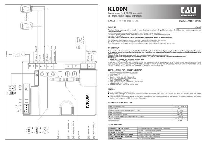
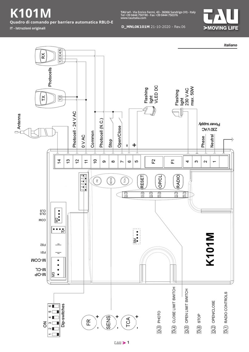
TERMINAL BOARD CONNECTIONS
Terminals Function Description
1 - 2 POWER SUPPLY POWER input 230/115 V AC 50-60 Hz. EARTH, 1= NEUTRAL, 2= PHASE;
3 - 4 FLASHING LIGHT FLASHING LIGHT Output FLASHING 230/115 VAC 50 W max.
5 - 6 LED
FLASHING LIGHT
FLASHING LIGHT Output FLASHING 12 VDC. Intermittent output during the operation, the ashing frequency is
doubled during closing;
7 - 10 OPEN/CLOSE OPEN/CLOSE input (Normally Open contact);
8 - 10 STOP STOP input (Normally Closed contact);
9 - 10 PHOTOCELLS
PHOTOCELLS OR SAFETY DEVICES input; active during closure (Normally Closed contact); the gate will stop
during closing and totally reopen it, (10= Common). If there is more than one safety device, connect all the NC
contacts IN SERIES.
11 - 12 24V AC
PHOTOCELLS 24 V AC 10 W output to Photocells, Receivers etc.; connect a up to 3 pair of photocells. 11= 0 V AC, 12= 24 V AC;
13 - 14 AERIAL 433,92 MHz built-in RX aerial input; 13= EARTH, 14= SIGNAL;
J4 APP quick plug-in for device connection for APP operation (mod. T-WIFI / T- CONNECT)
M2 LIMIT SWITCH Quick coupling for LIMIT SWITCH connection (Normally Closed contacts).
ORANGE= Closing Limit Switch (CLS), RED= Opening LimitSwitch (OLS), GREY= Common (COM);
FS1 - FS2 CAPACITOR CAPACITOR Terminals for motor start-up;
M3 MOTOR Quick coupling for 230 V AC single-phase MOTOR connection. BLUE= common (M-COM);
BROWN= closing (M-CL); BLACK= opening (M-OP).
SM MEMORY CARD quick plug-in for MEMORY CARD connection for transmitters codes.
LOGIC ADJUSTMENTS
TRIMMER
FR.
Motor torque adjustment. Turning the trimmer clockwise (+) the torque will be increased; Turning the trimmer coun-
terclockwise (-) the torque will be decreased.
Note: The trimmer is set to provide sucient thrust to work the gate within the limits established by
current standards (EN 12453).
SENS.
Obstacle detection setting. Turning the trimmer clockwise (+) the sensitivity will be increased; Turning the trimmer
counterclockwise (-) the sensitivity will be decreased.
Note: Before setting the obstacle detection, let the gate operator perform a complete opening and clos-
ing cycle.
T.C.A.
Automatic closing time adjustment. Turning the trimmer clockwise (+) time will be increased; Turning the trimmer
counterclockwise (-) the time will be decreased.
Note: The time values can be set between 1 and 120 seconds.
Dip switch
1AUTOMATIC
CLOSING
On automatic closing enabled.
O automatic closing disabled.
22 / 4 STROKE
On (with Automatic closing enabled) Two-Stroke operation mode OPEN-CLOSE, OPEN-CLOSE, etc.
O (with Automatic closing enabled) Four-Stroke operation mode OPEN-STOP-CLOSE-STOP, OPEN-
STOP-CLOSE-STOP, etc.
3SOFT-STOP
On
Turning DIP3 ON, the setting of the travel with slowdown is activated (see following paragraph). At
the end of the procedure, leave the dip ON if you want to keep the values obtained. If you turn it
OFF and then back ON, the SETUP procedure must be repeated.
O The working time is determined by the limit switches, no slowdown. Non-adjustable maximum working
time set at 96 seconds.
4OPENING
DIRECTION
On Left-hand leaf opening mode;
O Right-hand leaf opening mode;
5NO REVERS On While opening and during the T.C.A., the gate ignores the closing commands (NO REVERSE);
O The gate behaves as per the setting of dip-switch 2;
6BREAKING On breaking enabled;
O breaking disabled;
Note: the breaking system activates whenever the motor must stop and reduces the inertia accumulated by the gear motor
during movement.

SOFT-STOP SETTING
Set DIP3 to ON, active procedure (DL1 ashing) - Start with the sliding gate open
Close the AP/CH contact or press the OP/CL pushbutton: the operator will start closing the gate until the Closing Limit Switch
(CLS) is reached.
Once the Closing Limit Switch (CLS) is reached, the operator will reverse the cycle and start opening the gate:
1_ Close the AP/CH contact or press the OP/CL pushbutton when the desired start point of the Soft-stop is reached;
2_ Once the Opening Limit Switch (OLS) is reached, the gate will stop. DL1 LED will turn ON (start point set);
3_ If the STOP contact is opened the procedure is interrupted, the gate will stop and DL1 LED will ash to advise that the
procedure is still active (Close the AP/CH contact or press the OP/CL pushbutton to restart the procedure from the be-
ginning).
4_ At the end of the operation leave DIP3 in ON !!! (If it returns to OFF and then to ON, the operations described above must
be repeated);
Note: SOFT-STOP settings apply both to opening and closing.
ATTENTION: to modify the SOFT-STOP settings it is necessary to repeat the whole procedure.
K100M FEATURES
DL1 LED
Other than indicating the programming of a transmitter is going on, DL1 LED advises error messages as follows:
Steady light: Normal operation;
Fast ashing: Soft-Stop learning procedure activated;
Slow ashing: Automatic 50 / 60 HZ Frequency Detection Error;
Contact Technical Service;
6 ashes: obstacle present after 3 closing attempts;
Make sure the gate slides smoothly and without obstacles in both directions;
7 ashes: No learning procedure executed;
Perform learning procedure.
8 ashes: No motor signal;
Check wiring - Make sure the motor can rotate freely;
Multiple errors are indicated by a 2” pause between error messages. Messages will be shown until a complete opening/closing
cycle is performed.
In the event of 3 consecutive activations (during the same closing manoeuvre) of the amperometric control (obstacle detection),
the control unit opens completely on the next manoeuvre. To reset, the automation must complete a manoeuvre (opening
and then closing); otherwise the end stop search process will be repeated after each activation of the amperometric control.
In the event of activation (during the opening manoeuvre) of the amperometric control (obstacle detection), the control unit
closes approx. 20 cm. stopping the automation. On the next manoeuvre the control unit closes completely.
WARNING: the control panel logics may interpret mechanical friction as an obstacle.
ADVANCED FUNCTIONS
Clock function: a timer can be connected to the open-close pushbutton in order to keep the gate open at certain times during
the day, after which it reverts to automatic closing.
Note: The gate remains open as long as the OP/CL input continues to be activated.
433.92 MHz BUILT-IN RADIO RECEIVER
The built-in radio receiver can store up to 30 dierent codes from Rolling Code transmitters (S2RP, S4RP, K-SLIM-RP, T-4RP).
The radio channel directly commands the control board for opening the automatic device.
LEARNING PROCEDURE FOR TRANSMITTERS
REMOTE CONTROL LEARNING = OPENS/CLOSES
RADIO+OP/CL = PEDESTRIAN
1_ press and release the RADIO button on the control unit;
2_ DL1 LED turns OFF to indicate that the programming mode has been activated (if no code is entered within 10 seconds, the
control unit will exit the programming mode);
3_ press and release the transmitter button;
4_ DL1 LED turns ON again to indicate that the new code is stored (if this does not happen, wait 10 seconds and start again
from point 1);
5_ to store other transmitters, repeat the procedure from point 1 up to a maximum of 30 transmitters;
6_ if you wish to store the pedestrian control, repeat the procedure in point 1 pressing the RADIO+OP/CL 1 keys together
instead of the RADIO key;
7_ to exit the programming mode without storing a code, press and release RADIO button.
Note: When the maximum number of transmitter (30) is reached, the DL1 LED will start ashing fast for about 3”,
without performing memorisation.
REMOTE PROGRAMMING THROUGH T-4RP and K-SLIM-RP (V 4.X)

With the V 4.X software version it is possible to carry out remote learning with remote controls T-4RP and K-SLIM-RP (V 4.X),
that is without acting directly on the programming keys of the receiver.
It will be sucient to have an already programmed remote control in the receiver and you will be able to open remote pro-
gramming of the new remote controls. Follow the procedure in the instructions of the T-4RP and K-SLIM-RP (V 4.X) remote
controls.
ERASING ALL PROGRAMMED TRANSMITTERS
1_ press and hold the RADIO button on the control unit for approx. 3” to start the erasing procedure;
2_ DL1 LED ashes slowly to indicate that the erasing procedure has been activated;
3_ again, press and hold the RADIO button on the control unit for approx. 3”;
4_ DL1 LED turns o for approx. 3”, then turns ON To indicate that all stored codes have been cancelled;
5_ repeat the procedure in point 1 using the RADIO+OP/CL keys together to cancel all the controls associated with the PEDES-
TRIAN control;
6_ to exit the erasing mode, press and release RADIO button.
MEMORY CAPACITY
The code memory capacity* of the K100M can be expanded from 30 to 126, 254 or 1022 codes (transmitters) by replacing the
memory cards as follows
(plug them onto SM connector, see wiring diagram)
:
126 codes Art. 250SM126
254 codes Art. 250SM254
1022 codes Art. 250SM1022
* Control units are supplied with a standard built-in 30-code memory. The memory card for enhancing the code memory capacity
must be ordered separately.
To allow the previously stored codes (max. 30) to be moved to the control unit, it is required to install a memory card, making
sure that the control unit is at that time o and that the memory card is brand new and therefore completely empty.
When the control unit is restarted, the codes will automatically move to the memory card.
Moving the codes from the control unit to the memory card does not work if on the memory card used, radio control codes
have already been stored and the memory card has been subsequently erased.
To insert new radio controls, the operation described above shall be repeated.
WARNING: Control unit must be turned OFF to insert / remove a memory card.
RADIO MEMORY HARD RESET:
- press without releasing keys RESET+RADIO till LED DL1 starts ashing quickly. At this point release the keys and press them
again till the LED go o and on again, conrming the operation is complete.
RADIO MEMORY WRITING VIA TAUSOFT
To enable writing the radio memory with TAUSOFT, keep keys RADIO+OP/CL pressed while you connect the cable to connector
“SM” of K100M and keep them pressed until DL1 stops ashing. For information regarding radio programming with TAUSOFT,
refer to the relative manual.
SET-UP FOR OPERATION WITH TAU APPS
In order to use the TauApp and TauOpen apps, it will be necessary to connect to input J4 of the K100M control unit using the
supplied cable, the respective T-WIFI and T-CONNECT devices. To activate the operation of the apps see the respective instructions.
TROUBLESHOOTING GUIDE
Operator does not run
a- Check 230/115 V power supply with a voltmeter;
b- Check that all 4 green LEDs (Normally Closed contacts, DL3, DL4, DL5 and DL6) are ON, and that DL2 LED (Normally Open contacts) is
OFF. LED DL1 must be ON;
c- Check that the red DL1 LED is ON;
d- Check that the fuses are intact with a voltmeter.
The radio control has little range
a- Check that the ground and the aerial signal connections have not been inverted;
b- Do not make joints to increase the length of the aerial wire;
c- Do not install the aerial in a low position or behind walls or pillars;
d- Check the state of the transmitter’s batteries.
The gate opens the wrong way
a_ Invert the position of DIP 4 (after having turned o the power to the control unit).

MANUFACTURER’S DECLARATION OF INCORPORATION
(in accordance with European Directive 2006/42/EC App. II.B)
Manufacturer: TAU S.r.l.
Address: Via E. Fermi, 43 - 36066 Sandrigo (Vi) - ITALY
Declares under its sole responsibility, that the product: Electronic control unit designed for automatic movement of: Swing gate
for use in a: General environment complete with: Radioreceiver
Model: K100M Type:K100M
Serial number: see silver label Commercial name: Control panel for T-ONE5E gearmotor
Has been produced for incorporation on an access point (swing gate) of for assembly with other devices used to move such an access point, to constitute
a machine in accordance with the Machinery Directive 2006/42/EC.
Also declares that this product complies with the essential safety requirements of the following EEC directives:
- 2014/35/EU Low Voltage Directive - 2014/30/EU Electromagnetic Compatibility Directive
and, where required, with the Directive: - 2014/53/EU Radio equipment and telecommunications terminal equipment
Also declares that it is not permitted to start up the machine until the machine in which it is incorporated or of which it will be a component has been
identied with the relative declaration of conformity with the provisions of Directive 2006/42/EC.
The following standards and technical specifications are applied:
EN 61000-6-2; EN 61000-6-3; EN 60335-1; ETSI EN 301 489-1 V1.9.2; ETSI EN 301 489-3 V1.6.1; EN 300 220-2 V2.4.1;
EN 60335-2-103;
The manufacturer undertakes to provide, on suciently motivated request by national authorities, all information pertinent to the quasi-machinery.
Sandrigo, 08/11/2016
Legal Representative
_________________________________________
Loris Virgilio Danieli
Name and address of person authorised to draw up all pertinent technical documentation:
Loris Virgilio Danieli - via E. Fermi, 43 - 36066 Sandrigo (Vi) Italy
FR
SENS
TCA
F2
F1
7
6
5
8
9
10
11
12
13
14
1
2
3
Neutral
230 V AC
Power supply
Phase
M-OP
CLS
OLS
COM
FS1
FS2
M-COM
M-CL
4
RADIO
OP/CL
RESET
DL3
DL4
DL5
DL6
DL2
DL1
123456
123456
Flashing
light
230 V AC
max. 50W
Flashing
light
VLED DC
Open/Close
+
-
Stop
Antenna
K100M
Dip-switches
ON
M2
J4
SM
M3
DL3
DL4
DL5
DL6
DL2
DL1
PHOTO
CLOSE LIMIT SWITCH
OPEN LIMIT SWITCH
STOP
OPEN/CLOSE
RADIO CONTROLS
TCA
+-
SENS
+-
FR
+-
Photocells
Common
Photocell (N.C.)
RX
12345
TX
1 2
0 V AC
Photocell - 24 V AC
Other manuals for K100M
3
Table of contents
Other tau Control Panel manuals
