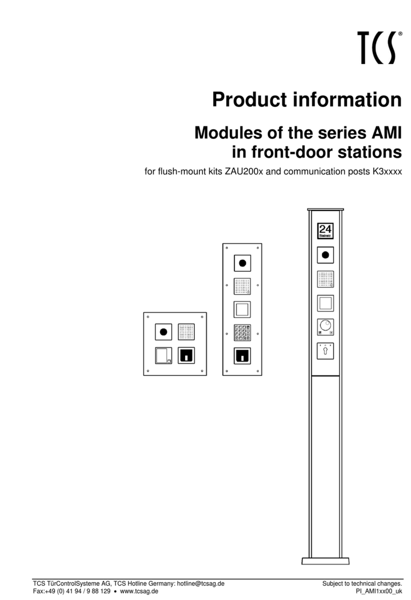
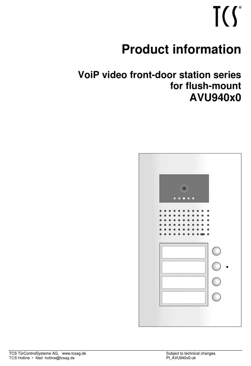
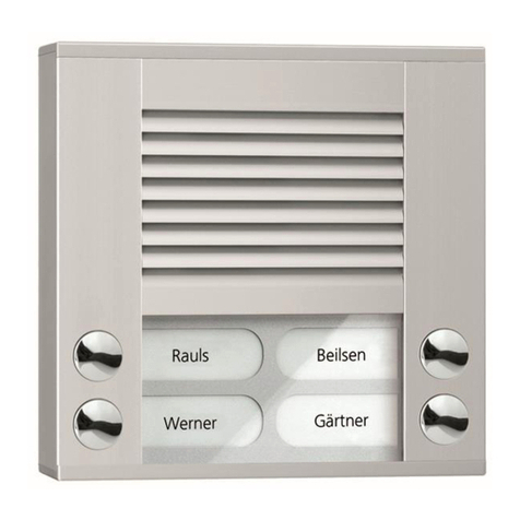
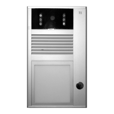
TCS AVD Series User manual

Product information
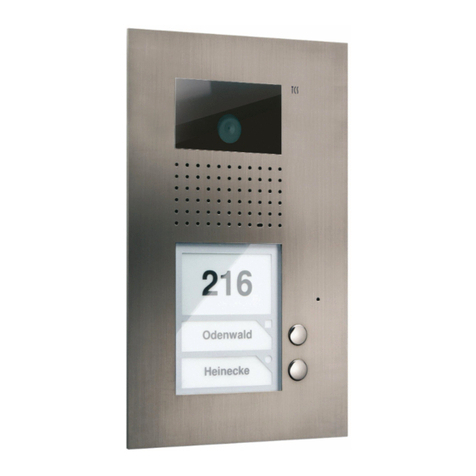
Front door station series AVD/AVE
with integrated code lock

Table ofcontents
Scope of delivery..........................................................................................................................................................4
introduction..................................................................................................................................................................4
Notes on this product information....................................................................................................................................................................... 4
Used symbols and warning notices .................................................................................................................................................................... 4
Further used symbols........................................................................................................................................................................................... 4
Safety instructions.......................................................................................................................................................5
General safety regulations ................................................................................................................................................................................... 5
requirements to protect against lightning ......................................................................................................................................................... 5
Terms ...........................................................................................................................................................................5
Product description .....................................................................................................................................................6
Intended use ........................................................................................................................................................................................................... 6
Short description.................................................................................................................................................................................................... 6
Device overview...................................................................................................................................................................................................... 7
Indication and operating elements...................................................................................................................................................................... 8
Technical data......................................................................................................................................................................................................... 8
Installation ...................................................................................................................................................................9
Installation site ....................................................................................................................................................................................................... 9
Mounting height ..................................................................................................................................................................................................... 9
Opening and closing the housing......................................................................................................................................................................... 9
Connecting the lines ..................................................................................................................................................10
Connect the floor push-button...........................................................................................................................................................................10
Example circuit.....................................................................................................................................................................................................11
Commissioning video ..........................................................................................................................................................................................11
Extended code lock function...............................................................................................................................................................................12
Initial operation..........................................................................................................................................................12
Connect the floor push-button...........................................................................................................................................................................12
Setting the volume of microphone and loudspeaker ...............................................................................................12
Labelling the name plates .........................................................................................................................................13
Configuration .............................................................................................................................................................13
Factory settings....................................................................................................................................................................................................13
Pre-set times........................................................................................................................................................................................................14
Configuration options ..........................................................................................................................................................................................14
Bell button programming..........................................................................................................................................15
Basic principle ......................................................................................................................................................................................................15
Legend................................................................................................................................................................................................................... 15
Programming a bell button................................................................................................................................................................................ 16
Programming a second indoor station at the same bell button (parallel call)........................................................................................... 16
Delete the programming ....................................................................................................................................................................................18
Programming the code lock ......................................................................................................................................18
Notes on the programming................................................................................................................................................................................18
Initiate programming ..........................................................................................................................................................................................19
Programming....................................................................................................................................................................................................... 19
Switch off the programming mode ................................................................................................................................................................... 20
Operating the code lock .............................................................................................................................................21
3
Door release in basic mode................................................................................................................................................................................21
Switching the light in basic mode ......................................................................................................................................................................21
Repair.........................................................................................................................................................................21
Exchanging the EEPROM storage.....................................................................................................................................................................21
FAQ .............................................................................................................................................................................22
Error indication/detection...................................................................................................................................................................................22
Cleaning .....................................................................................................................................................................22
Conformity .................................................................................................................................................................22
Information on disposal.............................................................................................................................................23
Warranty ....................................................................................................................................................................23
Service........................................................................................................................................................................23

4
Scope of delivery
1 x AVD/AVE with code lock (AVD54013, AVE54043, AVE54063, AVE54083, AVE54103, AVE54123)
1 x allen key DIN 911
1 x screw driver with round handle
name plates, with light symbol
product information, programming table
introduction
Notes on this product information
This product information refers exclusively to qualified electricians.
The product information of the video front door station series AVD/AVE contains important notes on intended use,
installation and commissioning. Please, keep the product information at a suitable place, where it is easily accessi-
ble for maintenance and repair reasons.
All product information are available for download at www.tcsag.de.
Used symbols and warning notices
Symbol signal word Explanation
DANGER! The signal word describes an endangering with a high level of risk. Failure to observe
this warning will result in death or very serious injury.
WARNING! The signal word describes an endangering with a medium level of risk. Failure to
observe this warning could result in death or very serious injury.
CAUTION! The signal word describes an endangering with a low level of risk. Failure to observe
this warning could result in a minor or moderate injury.
CAUTION! The signal word indicates, that damages on equipment, environment and property
can occur.
Further used symbols
important note or important information
►Step
cross reference For further information on this topic, see source
list, list entry 1 level
‐
list, list entry 2 level
a)
Explanation

5
Safety instructions
General safety regulations
Assembly, installation, commissioning and repair of electronic devices have to be carried out
only by a qualified electrician.
Observe the latest regulations and standards for system installations.
WARNING! Danger to life due to electric shock
Observe the safety regulations according to DIN VDE 0100, when working on main power connections of
230 V.
When installing TCS:BUS systems the general safety regulations for telecommunication systems ac-
cording to VDE 0800 must be observed. Inter alia:
separated cable routing of high and low voltage lines
minimum distance of 10 cm in case of a common cable routing
use of separators between high and low voltage lines within shared cable ducts
use of standard telecommunication lines, e.g. J-Y (St) Y with 0.8 mm diameter,
already existing lines (modernisation) with deviating cross-sections can be used in compliance with
the loop resistance.
requirements to protect against lightning
CAUTION! Device damage due to over-voltage
By suitable lightning protection measures it has to be ensured that the electric voltage of 32 V DC at
each connection is not to be exceeded.
Terms
Basic mode The system is in normal operation. Activate the programming mode of the front door station to con-
figure the system.
programming mode State in which you can enter access and master codes and change further basic settings (directly at
the front door station).
master code
The integrated code lock is equipped with a security code (master code) with a maximum of 8 digits.
Activate the programming mode of the code lock with this master code.
Delivery state: 12345678.
access code Security code with a maximum of 8 digits to confirm the code lock (e.g. direct triggering of the door
opener).

6
Product description
Intended use
The video front door station series AVD/AVE with integrated code lock is suitable for surface-mount in the outdoor
area.
Modifications and repair of the device are only permitted, as far as described in this product information
and executed by qualified electrician. Otherwise any claims under warranty and liability expire.
Always observe the current legislation and labelling requirements during assembly and operation of
video components.
Short description
Video front-door station
Video front door stations with code lock for surface-mount with 1, 4, 6, 8, 10 or 12 bell buttons.
Size of the nameplate: H 34 mm to 72 mm x W 74 mm (AVD), H 15 mm x W 39 mm (AVE)
Colour: anodised natural (EN)
colour camera CMOS sensor 380 TVL
focal length f = 2.0 mm (F 2.5)
light sensitivity 0 lux (IR on), 1 lux (IR off)
diagonal detection angle 130°
IR illumination for close-range illumination at night
camera can be operated continuously
metal housing made of robust aluminium profile
bell button made of metal with maintenance-free contacts
per bell button 2 indoor stations can be allocated
durable and energy-saving LED name plate illumination
shatter-proof name plate glass
acknowledgement tone when pressing the bell button
any bell bell button can be used to switch the light, light symbol enclosed
conversation time ex works: 56 seconds / can be adjusted with Service Device and configoTM
volume and microphone sensitivity can be adjusted manually
pluggable memory to exchange front door stations that are identical in construction
R-terminal to connect a functional extension: Door release
door release time at R-terminal ex works: 3 seconds / can be adjusted with Service Device and configoTM
Door call standby time ex works: 56 seconds / can be adjusted with Service Device and configoTM
voice connection in door call standby time / can be adjusted with Service Device
Code lock
switching the light by pressing the #-button without code entry, can be deactivated
0 codes, with a maximum of 8 digits for operation
1 master code for maintenance and configuration, leading zeros are accepted
code stop function to activate/lock a single code (only for memory loaction 1): Connecting a time switch (or motion
detector, brightness sensor, door contact of a lock etc.) to a bipolar pluggable screw terminal is possible
acoustic signalling when pressing the bell buttons, can be deactivated
acoustic and optical signalling when the code is recognised
acoustic and optical signalling when receiving a short door release protocol (if configured)
button 5 with marking

7
Device overview
1 microphone 10 drain for condensed water
2 front panel 11 lower aperture
3 EEPROM 12 bell button
4 connection terminal 13 connection for Service Device / bell button extension
5 two-coloured LED 14 nameplate illumination
6 Code lock keypad 15 volume control microphone
7 bipolar pluggable screw terminal 16 volume control loudspeaker
8 cable gland 17 loudspeaker
9 attachment hole 18 camera field with camera and IR illumination

8
Indication and operating elements
Term Function
LED is OFF device is in basic mode, no error is detected
LED green
ON (lights up for 3 s)
∙ positive input confirmation
∙ code number accepted (can be deactivated, adjustable lighting duration)
BLINKS: device is in programming mode
LED red
ON (lights up for 3 s):
∙ wrong entry
ON (lights up for 2 min):
∙ locked (after the code was entered 3 x incorrectly)
ON (lights up permanently)
∙ entry master code
LED orange FLASHES: total error indication
bell button trigger a door call
code lock keypad
operation, programming of code lock functions
∙ numeric buttons from 1 to 0
∙ #-button: light switching in basic mode, input confirmation in program-
ming mode
∙ *-button: entry of command sequences and abort of incomplete com-
mand sequences in programming mode
Technical data
supply voltage +24 V ± 8 % (power supply and control unit)
material of the housing aluminium
colour of the housing anodised natural
nameplate glass acrylic glass, printed, 5 mm thick
dimensions (in mm) housing H 242 to 318
x W 135 x D 20
camera field H 38 x W 82
camera colour camera CMOS sensor, 380 TVL
light sensitivity
0 lux (IR on), 1 lux (IR off);
automatic daytime / nighttime operation
focal length f 2.0 mm (F = 2.5)
diagonal detection angle 130°
video output 1 Vpp, symmetric, 1 Vss FBAS
acceptable ambient temperature -20 ...+ 50 °C
input current in resting position (6-wire
operation) I(a) = 0.6 mA I(P) = 80 mA
maximum input current I(Pmax) = 100 mA

9
Installation
Observe when installing further devices, that you can pull out the name plate glass downwards. Do not
mount another device below a device.
Installation site
To achieve an optimal video image quality do not point out the
camera to
solar radiation
strong sources of light
bright or strongly reflecting walls
Mounting height
Observe the detection angle of the camera when selecting the
mounting height of the video front door station (see PIC on the
right side). Persons with an average body height are detected
optimal at a mounting height of 1.6 m above the ground.
CAUTION! Device damage.
The front door station must never be sealed using silicon! Condensed water must be able to escape and
evaporate.
Opening and closing the housing
The lower aperture is connected to the aluminium profile with
2 hexagon socket screws.
►Loose both screws with an allen key.
►Now you can face away or remove the lower aperture.
►Pull out the name plate glass downwards.
►Guide the cable through the cable gland.
►Mount the device to the wall using the attachment holes and
suitable screws.
Ensure that the wires are not getting clamped below the spac-
ers at the rear side of the front door station.
►Slide the name plate glass upwards below the front panel.
►Fix the lower aperture again.
Ensure that the rubber seals within the guidance slot are not damaged when sliding in the name plate
glass.

10
Connecting the lines
acceptable cross section (diameter) 0.08 … 0.82 mm2 (Ø 0.32 … 1.0 mm)
maximum number of wires per terminal contact 2 x 0.8 mm, 3 x 0.6 mm
Connect further wires by using auxiliary terminals.
Use only connecting lines made of the same material and with the same diameter within one terminal
contact.
Detailed information on wire routing in TCS systems as well as on the loop resistance you'll find in the
system manual. Available under: http://www.tcsag.de/download/kataloge-prospekte-flyer
CAUTION! Device damage.
Use the small slot screwdriver (enclosed in the delivery) to connect lines. Avoid damaging the device.
CAUTION! Device damage.
The inner resistance of the door opener must not fall below 6 Ohm!
►Strip the cable ends.
►Connect the wires according to the connecting diagram depending on the type of system.
Do not place the wires in front of the LEDs. Otherwise this might affect the name plate illumination nega-
tively. Ensure that the wires are not getting clamped below the spacers at the rear side of the front door
station.
Connect the floor push-button
►Connect the floor push-button to the terminals E and P.
Alternatively you can connect the floor push-button to the terminals a and E.
Ensure that the a-wire of the power supply and control unit is connected to the a-terminal of the indoor
station.

11
Example circuit
Commissioning video
WARNING! Danger to life due to electric shock
First install all the devices of the system completely. Then switch on the mains voltage.
►Install the devices of the system completely.
►Do not connect V1 and V2 with the P-, a- or b-wire. Observe the polarity when connecting the video wires V1 (+)
and V2 (−).
►Proof the a-, b- and P-wire against each other on short-circuit.
►Switch on the mains voltage.

12
Extended code lock function
You can only use the extended code lock function for the first code (memory location). The function can be
set with the configuration software configoTM.
You can connect a time switch (alternatively: motion detector, brightness sensor, door contact of a lock etc.) to the
bipolar pluggable screw terminal (contacts 1 and 2, see
Device overview
). The switching input at the terminals 1 and
2 can be configured (opening/closing contact) and influences the effectiveness of the code on the first memory loca-
tion.
The additional device effects the code entry.
Example:
In combination with a time switch access is only granted / not granted in the determined period of time,
depending on the configuration.
The programmed action is executed, if the code is entered correctly and the contact, according to the configuration
of the switching input, is effective.
Initial operation
WARNING! Danger to life due to electric shock
Observe the safety regulations according to DIN VDE 0100, when working on main power connections of
230 V.
►Install the devices of the system voltage-free and completely.
►Do not connect the video wires V1 and V2 with the P-, a- or b-wire. Observe the polarity when connecting the vid-
eo wires V1 (+) and V2 (−).
►Proof the a-, b- and P-wire against each other on short-circuit.
►Switch on the mains voltage.
Connect the floor push-button
►Connect the floor push-button to the terminals E and P.
Alternatively you can connect the floor push-button to the terminals a and E.
Ensure that the a-wire of the power supply and control unit is connected to the a-terminal of the indoor
station.
Setting the volume of microphone and loudspeaker
CAUTION! Device damage.
Use the enclosed small screw driver to adjust the volume!

13
The volumes are set on an average value ex works. A change is
not always required. Observe that the amplification cannot be
set independently from each other when adjusting the volume
of loudspeaker and microphone. In case of a high volume, the
feedback effect (audible whistling) occurs.
Volume control
microphone
Setting the volume at the
indoor station
loudspeaker
Setting the volume at the
front door station
Labelling the name plates
The labelling templates for the series AVD/AVE are available
for download under
www.tcsag.de/download/beschriftungsvorlagen/
at our website.
Enter the required names into the labelling template.
Print the name plates on the special foil.
Cut the name plates to the right size.
Push the name plate into the gab in the name plate glass from
aside (ill. 11).
Print the name plates on the special foil. You can order the foil
directly at TCS: Writeable polyester film for name plates DIN
A4.
Configuration
The front door station is to be configured as two separate devices: Front door station PES and code lock.
Factory settings
The front door station is equipped with an EEPROM. In there the following settings are stored ex works:
AS-address for door release function 0
programming lock OFF = 0
The programming mode can only be set at the control unit ON = 1
acoustic acknowledgement of the bell button confirmation active = 1
send light switch protocol when pressing the # button active = 1
access codes 2 to 10 (on memory location number 2 to 10) not assigned
master code 12345678
extended code lock function (with additional condition) OFF = 0

14
Pre-set times
relay switch time around 3 sec
lighting duration of the LED relay switch time is adopted, around 3 sec (=255)
duration of the acoustic acknowledgement 3 sec (= 255)
Configuration options
Function manually TCSK
configoTM
as of version 1.9.x.x
AVD/AVE
Programming the bell buttons x x x
Delete a bell button x x x
Determine the AS address x x
lock/unlock AS address x x
programming lock on/off x x
Send control function x x
light switch function on/off x x
door opener only during active door standby on/off x x
Speaking only during active door standby on/off x x
door opener only during an established voice connection on/off x
setting the door call standby time x
setting the limit for the conversation time x x
setting the call time x
setting the door release time x
selecting an acknowledgement tone (in case of a door call) x x
Code lock
determine/change access codes x x
determine the protocol that is sent when entering the code x x
delete data set (each a memory location) x x
Determine the AS address x x
determine options x x
programming lock x x
extended code lock function (switching input terminals 1 and 2 effec-
tiveness opening/closing contact) x x
change master code x x
reload factory settings x x
light switch protocol after pressing the # button x
key tone x
initiate the programming mode via the control unit x
free protocol 1 to 4 x

15
Bell button programming
Basic principle
All devices at the TCS:BUS have an unique serial number.
The serial number of the indoor station is allocated to the bell button of the front-door station. The allocation is
stored in the EEPROM of the front-door station.
Requirements for the programming:
►Ensure that the access to the indoor station in the flat is granted.
►Check if the indoor station is connected to the TCS:BUS.
►Switch on the mains voltage. The operating LED at the power supply and control unit is on.
►Check if no programming lock is set.
Before you can reprogram an already programmed bell button, you have to delete the programming.
Legend
press button shortly busy tone
Press the button until... a negative acknowledgement tone sounds
(bell button is already programmed)
release the button SNapp-tone
go on NoProg-tone (negative acknowledgement
tone)
ring tone deletion tone sequence
Progsperr-tone
Prog2-tone (programming of the 2nd serial
number starts)
Audio files of the call and acknowledgement tones are available online at: www.tcsag.de/download/ruf-
und-quittungstoene

16
Programming a bell button
1 Switching on the programming mode
power supply and control unit
Shortly press the RUN/PROG button. The LED blinks. The programming mode of the system is switched ON.
2a Programming via voice communication
or
Establish a voice communication to the
front-door station.
Shortly press the bell button at the
front door station.
A ring tone sounds at the front door and indoor
station.
2b alternatively: Programming via floor push-button
Shortly press the floor push-button twice in
quick succession. Each a ring tone sounds.
Shortly press the bell button at
the front door station.
A ring tone sounds at the front door and indoor
station.1)
Repeat the steps until you have programmed all bell buttons.
4 End programming mode
Shortly press the RUN/PROG button. The LED is on. The programming mode of the system is
switched OFF.
1)
If there sounds a Progsperr tone instead, at the front-door station a programming lock is set. You can deactivate the programming lock
only with the Service Device TCSK or the configuration software configoTM .
Programming a second indoor station at the same bell button (parallel call)
If a parallel call is configured, 2 indoor stations are called with 1 bell button at the front door station. The floor push-
button only calls the firmly wired indoor station. If bell button and floor push button should have the same functional-
ity, the function parallel allocation is to be used. On this occasion several indoor stations respond to the same bell
button as well as to the same floor push button. The parallel allocation is to be configured with the Service Device
TCSK or the configuration software configoTM .

17
Repeat the programming of an already programmed bell button, always change only the second serial
number. If you want to change the serial number that was programmed first, you have to delete both
serial numbers and then reprogram both serial numbers.
1 Switching on the programming mode
power supply and control unit
Shortly press the RUN/PROG button. The LED blinks. The programming mode of the system is switched ON.
2a Programming via voice communication
or
Establish a voice communication
to the front-door station.
Press the bell button until after 6 s a
Prog2 sounds, keep the button pressed
and after another 6 s a NoProg-tone
sounds and ...
…a ring tone sounds at the front
door and indoor station.1)
Release the bell
button.
2b alternatively: Programming via floor push button (if the indoor station is inaccessible)
Shortly press the floor push-button
twice in quick succession. Each a
ring tone sounds.
Press the bell button until after 6 s a
Prog2 sounds, keep the button
pressed and after another 6 s a
NoProg-tone sounds and ...
…a ring tone sounds at the front
door and indoor station.1)
Release the bell
button.
Repeat the steps until you have programmed all bell buttons.
4 End programming mode
Shortly press the RUN/PROG button. The LED is on. The programming mode of the system is switched
OFF.
1)
If there sounds a Progsperr tone instead, at the front-door station a programming lock is set. You can deactivate the programming lock
only with the Service Device TCSK or the configuration software configoTM .

18
Delete the programming
Before an already programmed bell button can be programmed newly, the programming must be deleted.
1 Switching on the programming mode
power supply and control unit
Shortly press the RUN/PROG button. The LED blinks. The programming mode of the system is switched ON.
2 Delete a bell button
Press the bell button until the deletion tone sequence sounds. Release the bell button.
4 End programming mode
Shortly press the RUN/PROG button. The LED is on. The programming mode of the system is switched
OFF.
Programming the code lock
Notes on the programming
confirm with the # button
abort with the * button
Entries without confirmation have a timeout of 10 sec, an acknowledgement tone signals the countdown of the
timeout
factory settings of the 10 code memory locations are shown in brackets (e.g. WE = 0)
SpNo = number of the memory location

19
Initiate programming
0 Switching on and off the programming
mode of the system
at the control unit:
∙ Shortly press the RUN/PROG button, the LED blinks.
∙ Shortly press the RUN/PROG button, the LED lights up.
At the Axx5xxx0:
the two-coloured LED flashes green for 2 min
1 Activate the programming mode of the
device
enter the master code (start with the pro-
gramming within the next 2 min)
Correct input
Wrong input, unknown master code
No input
Input: * master code # (WE = 12345678)
A positive acknowledgement tone (1 x beep) sounds for 1 sec. The LED
blinks green for 2 min.
The device is ready for the programming.
A negative acknowledgement tone (3 x beep) sounds when pressing the
#-key. You can only enter a code 3 times incorrectly. Afterwards the
code input is locked for 2 min.
Then start again.
If no command is entered within the next 2 minutes, the device auto-
matically quits the programming mode. The LED expires.
Programming
2a Determine/change access codes
first access code
second access code
etc.
Input: * 0 # SpNo1 # access code # access code #
Input: * 0 # SpNo2 # access code # access code #
SpNo = 1 to 10
access code = number with a maximum of 8 digits
When changing the code, the old code is overwritten wirh the new one.
2b Send protocol when entering the code Input: * 2 # SpNo # P # P – protocol selection
SpNo = 1 to 10 (WE = 0 for SpNo 1 to 10)
P = 0 (door release protocol with unique AS address)
1 (control function1 with unique serial number)
6 (control function SpNo with unique serial number)
2c Delete data set
for a specific memory location
Input: * 3 # SpNo #
SpNo = 1 to 10 (data set inactive)
2d Enter the AS address Input: * 4 # AS-address #
AS address = 0 to 63 (WE = 0)

20
2e Determine options Input: * 5 # option # value #
option value
0 send light switch protocol 0 = no, 1 = yes (WE = 1)
3 acoustic acknowledgement
buttons
0 = off, 1 = on (WE = 1)
4 programming mode can only
be activated after the pro-
gramming mode of the control
unit was activated
0 = no, 1 = yes (WE = 0)
The factory setting is valid for stand alone operation. To
improve the safety, activate the option 4 (putting the
value to 1) during the BUS operation. Thus, the access
to the control unit is an additional condition.
2f Block manual programming Input: * 10 # master code #
master code = number with a maximum of 8 digits
The programming lock cannot be deactivated manually,
but only with configoTM.
Determine the
extended code lock function
Input: * 12 # function type #
Function type:
0 = external contact has no influence
1 = contact must be opened so that the code input can be effective
2 = contact must be opened so that the code input can be effective
2g Change master code Input: * 98 # old master code # new master code #
new master code #
new master code = number with a maximum of 8 digits
Change the pre-set master code when commissioning
the device.
2h Reload factory settings Input: * 99 # master code # master code #
master code = number with a maximum of 8 digits
All saved numeric codes are deleted. The master code
is reset to the factory setting.
Switch off the programming mode
2i Quit the programming mode Input: * 9 #
This manual suits for next models
7
Table of contents
Other TCS Intercom System manuals