TCS IVW3012-0110 User manual

TCS TürControlSysteme AG Subject to technical changes.
E-Mail: hotline@tcsag.de • www.tcsag.de PI_IVW3012_0x10_uk.doc
Product information
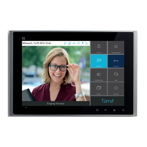
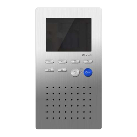
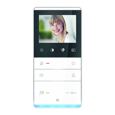
Video indoor stations color skylineTM
IVW3012-0x10
IVW3012-0110 surface-mount
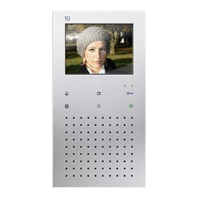
IVW3012-0210 flush-mount

2 07/2012
TCS TürControlSysteme AG Subject to technical changes.
E-Mail: hotline@tcsag.de • www.tcsag.de PI_IVW3012_0x10_uk.doc
Table of contents
Scope of delivery...............................................................................................................3
Safety instructions.............................................................................................................4
General safety regulations ...............................................................................................4
Installation –protective measures....................................................................................4
Device overview.................................................................................................................5
Indication and opeating elements....................................................................................5
Intended use.......................................................................................................................7
Short description...............................................................................................................8
Mounting and installation .................................................................................................9
Install the lower cover.......................................................................................................9
Mounting height............................................................................................................9
1Fixing the surface-mount box ................................................................................9
1Fixing the flush-mount box...................................................................................10
2Connecting the lines............................................................................................10
3Connect the components.....................................................................................11
4Put on the front panel unit into a surface-mount box...........................................11
4Put on the front panel unit into a flush-mount box ...............................................11
Disassembly...................................................................................................................12
Surface-mount devices...............................................................................................12
Flush-mount devices...................................................................................................12
Wiring example...............................................................................................................13
Connection diagram.......................................................................................................13
Note: for LSA terminal points .........................................................................................13
Commissioning................................................................................................................18
Error detection and display.............................................................................................14
Install the indoor station as end device ..........................................................................14
Configuration ...................................................................................................................15
Pre-settings ex works.....................................................................................................15
AS-adress dependent image activation......................................................................15
Preset times................................................................................................................16
Configuration options .....................................................................................................16
Programming the function key with the Service Device..................................................17
Help function ..................................................................................................................17
Setting the menus internal calls and control functions....................................................18
Simple.........................................................................................................................18
ON/OFF......................................................................................................................18
EnOcean.....................................................................................................................18
Receiving short messages .............................................................................................19
Operation..........................................................................................................................19
General ..........................................................................................................................19
Symbols and their meaning ........................................................................................19
Adjust ring tone parameter.............................................................................................20
Adjust image parameter.................................................................................................21
Symbols in the live image...........................................................................................21
Reset to factory setting...................................................................................................22
Select the camera by topstitching with the image button................................................22
Activating / deactivating zoom mode ..........................................................................23
Navigating in the image with the four navigation keys....................................................23
External image buffer.....................................................................................................23
07/2012 3
TCS TürControlSysteme AG Subject to technical changes.
E-Mail: hotline@tcsag.de • www.tcsag.de PI_IVW3012_0x10_uk.doc
Activating / deactivating the automatic image storage................................................23
Store an image manually............................................................................................24
View stored images ....................................................................................................24
Delete a stored image.................................................................................................24
Delete all stored images.............................................................................................25
Setting date and time of the image buffer ......................................................................25
Internal calls...................................................................................................................26
Send internal calls......................................................................................................26
Receive an internal call...............................................................................................26
Control functions............................................................................................................26
Sending and displaying control functions ...................................................................26
Short messages.............................................................................................................27
Reading short messages............................................................................................27
Deleting short messages............................................................................................27
General information on the conduit in TCS video systems.........................................27
6-wire operation .............................................................................................................27
Loop resistance principle............................................................................................28
Loop resistance measurement ...................................................................................28
Max. number of IVW3012 in 6-wire operation................................................................28
Technical data..................................................................................................................29
FAQ...................................................................................................................................29
Cleaning............................................................................................................................31
Conformity........................................................................................................................32
Information on disposal..................................................................................................32
Warranty...........................................................................................................................32
Service..............................................................................................................................32
Scope of delivery
1 x IVW3012 (surface-mount box or flush-mount box and front unit)
Product information
Instruction manual

4 07/2012
TCS TürControlSysteme AG Subject to technical changes.
E-Mail: hotline@tcsag.de • www.tcsag.de PI_IVW3012_0x10_uk.doc
Safety instructions
General safety regulations
!
Attention! Mounting, installation, commissioning and repair of electronic devices have
to be carried out only by qualified electricians. Thus, the valid standards and instruc-
tions for the installation of electrical systems have to be observed.
When working on systems with a main connection of 230 V alternating voltage, the safety
requirements according to DIN VDE 0100 have to be observed.
During the installation of TCS:BUS systems the general safety regulation for telecommuni-
cation systems according to VDE 0800 have to be observed. Inter alia:
separated conduit of heavy current and low current lines,
minimum distance of 10 cm in case of a common conduit,
use of separators between heavy and low current lines when using shared cable ducts,
use of standard telecommunication lines, e.g. J-Y (St) Y with a diameter of 0.8 mm,
existing lines (modernisation) with deviating cross-sections can be used in compliance
with the loop resistance.
Installation –protective measures
!
With suitable maesures to protect against lightning it has to be ensured that a voltage
of each 32 V DV is not to be exceeded at the connections a, b, P, E, M, V1, V2, C.

07/2012 5
TCS TürControlSysteme AG Subject to technical changes.
E-Mail: hotline@tcsag.de • www.tcsag.de PI_IVW3012_0x10_uk.doc
Device overview
The construction elements indicated with dashed lines are located at the inside of the front panel unit.
Indication and operating elements
designation
function
display
displays the video image
display ring tones and image parameter, as well as
menus of the On-Screen-Display (OSD)
menu button
call main menu (if the device is in stand-by mode)
call menu image parameter (if the live image is ON)
select and confirm image parameter menu or ring tone
parameter menu
select and confirm: main, internal call or control function
menu
start video / image reproduction (if mode to store imag-
es is activated)
call image buffer menu and time setting
display
1 indication for short
messages
2 function display for
door release automatic
/ call diversion
3 image buffer indica-
tion
4 call OFF indication
5 speaking indication
6 operation indication
door release button
function key
call OFF button
image button
button to store images
microphone
loudspeaker
navigation keys
UP, DOWN, LEFT,
RIGHT
connection cable
V
speech button
menu button
retaining magnets
12 3 4 5 6

6 07/2012
TCS TürControlSysteme AG Subject to technical changes.
E-Mail: hotline@tcsag.de • www.tcsag.de PI_IVW3012_0x10_uk.doc
navigation key UP
press shortly
panning upwards of the live image detail
select a list entry upwards in the internal call or control
function menu
increase the value of a selected parameter
zoom mode: enlarge the image
press and hold (longer than 4 sec)
+ navigation key DOWN: reset to factory setting
navigation key
DOWN
press shortly
panning downwards of the live image detail
select a list entry downwards in the internal call or con-
trol function menu
reduce the value of a selected parameter
zoom mode: downsize the image
press and hold (longer than 4 sec)
delete image in the image buffer (indication)
+ navigation key UP: reset to factory setting
navigation key LEFT
Panning of the live image detail to the left
navigation in the menus, sub menus, parameter or in
image buffer mode
image reproduction: forward to the prior image
navigation key
RIGHT
panning of the live image detail to the right
navigation in the menus, sub menus, parameter or in
the image buffer mode
image reproduction: forward to the next image
image button
press shortly
switch on the live image or switch between different
cameras, when the live image is displayed
exit zoom mode
directly call up short message menu directly, if a new,
unreaded short message exists (only possible, if no call
is incoming and speaking is not activated)
press and hold (longer than 4 sec)
live image, activate zoom mode
function key
press shortly
switching lights (= flat**)
alternatively:
send control function 8, make internal calls, door re-
lease automatic ON/OFF, call diversion ON/OFF
call up control function menu or internal call menu (can
be configured with configuration software configo™)
switch off OSD menu indication
image buffer button
press shortly,
if LED is ON: record video / image manually (only if a
live image is displayed)
if LED blinks: call up image buffer menu
press and hold (longer than 4 sec)
activate / deactivate automatic image recording

07/2012 7
TCS TürControlSysteme AG Subject to technical changes.
E-Mail: hotline@tcsag.de • www.tcsag.de PI_IVW3012_0x10_uk.doc
call OFF button
turn OFF ring tone
end communication, if the video indoor station IVW3012
is configured as simplex communication device (with
configuration software configoTM)
speech button
call acceptance, activate communication, simplex
communication
end communication
door release button
open the door (= flat**)
end communication
trigger light switch function***
LED 1, green:
short message indi-
cation
blinks: unreaded, new short messages
LED 2, red:
function indication T
door release auto-
matic / call diversion
ON: door release automatic or call diversion is activated
OFF: door release automatic or call diversion is deac-
tivated
LED 3, yellow:
image buffer indica-
tion
ON / OFF: automatic to storage of images is activated /
deactivated
blinks: indication new stored image
LED 4, red:
call OFF indication
ON: call OFF is activated
LED 5, green:
communication
indication
ON: door call, incoming internal call, communication is
activated
blinks: indication communication/ video channel is busy
LED 6, blue:
operation indication
ON: indicates operational readiness
flashes: error indication
** flat = preset at the factory
*** if light switch function is activated at the front-door station
Intended use
IVW3012 are video indoor stations of the skyline series with color display for hands-free
talking and simplex communication. They are suitable for the operation in building
communication systems in combined audio / video systems.
The operation is realised through buttons and the On-Screen-Display (OSD).
The video indoor station IVW3012-0110 is suitable for surface-mount and the video in-
door station IVW3012-0210 for flush-mount and cavity wall mounting.
Both are suitable for indoor use.

8 07/2012
TCS TürControlSysteme AG Subject to technical changes.
E-Mail: hotline@tcsag.de • www.tcsag.de PI_IVW3012_0x10_uk.doc
Short description
audio and video features
hands-free talking, manually controlled simplex communication can be activated
automatic hands-free talking after internal call / can be activated with configo™
acoustic call distinction in case of 2 different door calls (less than or equal to audio AS
borders and larger than audio AS border), 4 sub door calls, floor call and internal calls
1 parallel call / can be activated with configo™
selection out of 13 polyphonic ring tones, adjustable via OSD
possibility to trigger max. 10 internal calls and max. 10 control functions with nomination
/ can be adjusted with configo™
floor video function
ring tone volume can be adjusted via OSD
brightness, contrast, color saturation can be adjusted via OSD
max. 10 short messages can be received and displayed
audio and video privacy function as well as automatic call cut-off
buttons
blue door release button
speech button for hands-free talking resp. reversing key speaking/hearing when simplex
communication is activated
call OFF button with optical indication by red LED
image button to switch ON the image resp. to switch between different cameras
image button button to operate the central image buffer FVM1000
1 functions key with optical indication, ex works: assigned with control function / alter-
nate allocation can be activated: internal call, door release automatic, call diversion,
control function menu or call up internal call menu / adjustable with configo™
menu button to activate, control the OSD menu
4 cursor buttons for OSD navigation, adjustment and camera control
LED indication functions
optical indication of incoming calls
optical indication sensor and door release automatic / call diversion
optical indication of a busy line in case of an existing communication
optical indication of the ring tone mute by red LED
optical indication of unread short messages
optical indication image buffer is activated / stored images available
optical operation and error indication, blue (can be switched off)
connections
connection for floor push button within the device
external floor camera (C-terminal)

07/2012 9
TCS TürControlSysteme AG Subject to technical changes.
E-Mail: hotline@tcsag.de • www.tcsag.de PI_IVW3012_0x10_uk.doc
Mounting and installation
Install the lower cover
!
Attention!
The video indoor stations have to be installed and disassembled only without voltage!
!
Ensure that the screws are not over tightened when installing the surface- / flush-
mount box on uneven ground. If the screws are over tightened the surface- / flush-
mount box could deform. Then, it is possible that the device cannot be installed cor-
rectly.
Mounting height
For an optimal viewing angle we recommend a mounting height of 1.6 meter (top edge of
the device above the floor).
1 Fixing the surface-mount box
Insert the lines through the cable gland.
Fix the surface-mount box with suitable screws to the wall.
Ensure the correct position: The arrow must face upwards!
connector socket
connection cable of the front panel unit
attachment
holes
3
1
2
cable gland
support plate (4 x)
cable compartment
(height ca. 10 mm)
arrow for orientation
!
surface-mount box

10 07/2012
TCS TürControlSysteme AG Subject to technical changes.
E-Mail: hotline@tcsag.de • www.tcsag.de PI_IVW3012_0x10_uk.doc
1 Fixing the flush-mount box
Insert the lines through the cable gland.
Fix the flush-mount box with suitable screws to the wall or in the cavity wall. Ensure the
correct position: The arrow must face upwards!
The flush-mount box should be flush with the wall.
2 Connecting the lines
!
Use a suitable small screwdriver to connect the lines and to avoid damaging the de-
vice.
Strip insulation of the line ends.
Connect the lines according to the connecting diagram (see also labeling at the type
label).
connector socket
connection cable of the front panel unit
attachment
holes
3
1
2
cable gland
support plate (2 x)
cable compartment
(height ca. 10 mm)
arrow for
orientation
gspfeil
butterfly nuts
(4 x)
guide holes (2 x)
flush-mount box
!

07/2012 11
TCS TürControlSysteme AG Subject to technical changes.
E-Mail: hotline@tcsag.de • www.tcsag.de PI_IVW3012_0x10_uk.doc
3 Connecting the components
Surface-mount box / flush-mount box and front panel units have to be connected before
the assembling by a ribbon cable, which is located at the front panel unit.
Insert the free connector into the connector socket in the surface-mount box / flush-
mount box. Follow the color coding of the lines!(see illustrations above)
4 Fixing a front panel unit onto a surface-mount box
Surface-mount box and front panel unit are held together by 4 strong retention magnets.
When fixing the front panel unit to the surface-mount box, use the following procedure:
Take care that the connection cable and the ribbon cable are placed carefully in the ca-
ble compartment to avoid damaging the device.
Fix the front panel to the the lower support plate.
Press the front panel unit onto the surface-mount box until it is safely attached and all
edges are flush with the surface-mount box.
4 Fixing a front panel unit onto a flush-mount box
Flush-mount box and front panel unit are held together by 4 strong retention magnets.
When fixing the front panel unit to the flush-mount box, use the following procedure:
Take care that the connection cable and the ribbon cable are placed carefully in the ca-
ble compartment to avoid damaging the device.
Place the front panel unit with the guide pins into the guide holes of the flush-mount
box.
Press the front panel unit onto the flush-mount box until it is safely attached and firmly
positioned against the wall.
If the flush-mount box is lowered to deep into the wall or if the front panel unit is not po-
sitioned flush against the wall, the height of both surface plates can be changed:
–Loosen the butterfly nuts a little bit.
–Change the position of the support plate.
–Then tighten the butterfly nuts again.

12 07/2012
TCS TürControlSysteme AG Subject to technical changes.
E-Mail: hotline@tcsag.de • www.tcsag.de PI_IVW3012_0x10_uk.doc
Disassembling the device
surface-mounted devices
Hold the front panel unit with both hands.
Pull it carefully off the wall.
!
Make sure that the ribbon cable is not damaged.
flush-mounted devices
There is an oval release opening at the underside of the device. Insert a short screw-
driver with around 7 mm width into this opening (1).
Hold the front panel unit with both hands.
Press the screwdriver handle slightly to the wall (2).
The front panel unit can be removed now (3).
!
Make sure that the ribbon cable is not damaged.
4 retention magnets

07/2012 13
TCS TürControlSysteme AG Subject to technical changes.
E-Mail: hotline@tcsag.de • www.tcsag.de PI_IVW3012_0x10_uk.doc
wiring example
connection diagram
Note for LSA terminal points
!
Any forms of LSA terminal points cannot be used to install a TCS:BUS system.
connection
floor camera
floor push
button
floor push
button

14 07/2012
TCS TürControlSysteme AG Subject to technical changes.
E-Mail: hotline@tcsag.de • www.tcsag.de PI_IVW3012_0x10_uk.doc
Commissioning
!
First install the system completeley, then connect it to the power supply!
Install the devices of the system completely.
Do not connect V1 and V2 with P-, a- or b-wire. When connecting the video wires
V1 (+) and V2 (-) observe the polarity. If the video image is distorted after the com-
missioning, switch off the device and exchange the wires for the video signal.
Check the a-, b- and P-wire against each other on short-circuit.
Switch on the mains voltage.
Error detection and indication
Errors are signaled optically when detected and acoustically on keystroke: single error
tone and permanent flashing of the operation indication. When presssing any button of the
video indoor station IVW3012 the error tone sounds again. The optical error indication
stays active until the error is corrected.
error causes
indication
error
mode
error
tone
solution
a- and P-wire are mixed up
or short-circuited
blue ope-
ration
LED
flashes
exchange a- and P-wire or remove short-circuit,
device enters stand-by mode again
a- or M-wire: not connect-
ed or not supplied
connect a- resp. M-wire or check power supply,
device enters stand-by mode again
button clamps (pressed
longer than 15 sec)
release button at IVW3011 or floor push button, de-
vice enters stand-by mode again
Install the indoor station as end device
The indoor station is at the end of a strand or the only device on the strand:
Open the device. See Disassembling the device, page 12.
Put on the terminating resistor horizontally onto both contacts.
Delivery state: terminating resistor not plugged *(diagonal, plugged to one contact.
Close the device).

07/2012 15
TCS TürControlSysteme AG Subject to technical changes.
E-Mail: hotline@tcsag.de • www.tcsag.de PI_IVW3012_0x10_uk.doc
front panel unit, inside
* terminating resistor not plugged:
For converting a device, the jumpers are retained by plugging each of them to only one of the contact pins.
Configuration
Factory Pre-settings
AS address dependent image activation
If front-door stations without camera are also installed in systems with IVW3011 video
front-door stations, the video image is not activated, if a call from a front-door station with-
out camera is incoming.
To guarantee this function, the possible AS addresses are separated in two sections:
AS address
0 –31*
reserved for video
front-door stations
image is activated in case of a door call
(from max.16 video front-door stations)
AS address
ab 32*
free, for front-door
stations without cam-
era
image is not activated in case of a door call
*) The video AS border can be changed with the configuration software configoTM.
Note:
The AS addresses of the front-door stations have to be allocated with Service Device or configuration software configoTM.
plugged
delivery state:
not plugged
terminating resistor

16 07/2012
TCS TürControlSysteme AG Subject to technical changes.
E-Mail: hotline@tcsag.de • www.tcsag.de PI_IVW3012_0x10_uk.doc
Preset times
communication time
max. 2 min
remaining communication time after pressing
the door release button
around 4 sec
image switching time
80 sec
blinking period of the communication indica-
tion (LED, green), if ”video / communication
channel is busy“ when pressing the speech or
the image button
6 sec
blinks 3 x
internal standby time
around
30 sec
floor door release time
around 30 sec
timeout OSD menu (after the last keystroke)
10 sec
timeout OSD symbols in the live image
(after pressing the speech buttons)
3 sec
Configuration options
function
menu
TCSK-01
configoTM
as of version 1.6.
adjust ring tone volume
x
–
x
ring tone selection for 2 door calls,
sub door calls, internal calls and
floor call
x
–
x
adjust image parameter: brightness,
contrast, color saturation
x
reset to factory setting
x
–
x
assign function key with light, inter-
nal call, door release automatic, call
diversion or control function 8
–
x
x
parallel allocation
–
x
x
block ring tone output
–
x
–
call up control function menu or in-
ternal call menu with the function
key
–
–
x
allocate / delete floor door release
function
–
–
x
allocate / delete automatic hands-
free talking after internal call
–
–
x
define video AS border and
audio AS border
–
–
x
image activation in case of an in-
coming floor call
–
–
x
define internal call destinations (by
sending the sender serial number)
(source display at IMM1100, IMM2100 or
IVW3011 / IVW3012 possible)
–
–
x

07/2012 17
TCS TürControlSysteme AG Subject to technical changes.
E-Mail: hotline@tcsag.de • www.tcsag.de PI_IVW3012_0x10_uk.doc
unlimited communication time
(limit is set only by the device to which the
communication is established)
–
–
x
fixed simplex communication
–
–
x
simplex communication to the front-
door station
–
–
x
permanent image activation
–
–
x
receiving / blocking short messages
–
–
x
Programming of the function key with the Service Device
The indoor station is acting as an intercom simplex communication device.
Use the orders “9“ to configure comfort intercom simplex communication devices (see
product information Service Device):
A programming with the orders ”9“ has to be initiated once with the order *95#ser. no.#.
Then the programming of the function key has to be realised with the Service Device.
initiation
call diversion
door release automatic
internal call
control function 8
restore light switch function
parallel allocation
Note: Deaktivating the parallel allocation
means the automatically allocation of the
serial number 0.
ser. no. = serial number of the indoor station which has to be newly configured
targetSno.= serial number of the target indoor station to which the call is to be redirected
intSno. = serial number of the target indoor station to which internal calls are made
ParSno. = serial number of the indoor station, to which the indoor station which hast o be newly configured is
allocated to
Help function
For facilitating the operation of the device, symbols
are faded in in the right upper corner when the live
video image is activated or the main or sub menus
are called. The symbols indicate the buttons that are
available in the corresponding screen (e.g. menu
control functions). The fade-in automatically ends
after 5 seconds or after the first keystroke.

18 07/2012
TCS TürControlSysteme AG Subject to technical changes.
E-Mail: hotline@tcsag.de • www.tcsag.de PI_IVW3012_0x10_uk.doc
symbol
meaning
navigation buttons RIGHT, LEFT, UP and DOWN can be used for control-
ling
only the navigation button RIGHT, LEFT can be used for controlling
only the navigation buttons UP, DOWN can be used for controlling
the menu button can be used to confirm
the function key can be used to abort
the navigation button DOWN can be pressed and hold for 4 sec
Setting the menus internal calls and control functions
Entries into the menus. These points can be entered with the configuration software
configo™ via a limited character set and also uploaded into the device.
Each entry of the control function menu can be processed in 3 different ways:
Simple
With each triggering the same control protocol is sent. There will be no indication for the
state of the device that is switched. The serial number and the control function number can
be configured as parameter. Thus, it is also possible to automatically generate the own
serial number of the video indoor station IVW3012.
ON/OFF
Two different control protocols with the same serial number are sent alternately. One con-
trol function number is assigned to switch-on and the other to switch-off. Via two different
symbols, which appear alternately in front of the list entry, the state, which is switched last,
can be seen. Both control function numbers and the serial number can be configured, if
required, the device-individual serial number can also be generated.
EnOcean
This function is realised identically to the IMM1100. Thus, an EnOcean radio interface
FBI4200 can be connected. It can also be used to display switching states, without influ-
encing it. When triggering the list entry, a control function with a configurable serial number
is sent. The control function number can be freely selected (0 to 200 possible). Independ-
ent from sending the protocol, receiving the control protocols with the configured serial
number causes a switch over between the states. As shown under b), this is displayed by
symbols in front of the list entry. Thereby, the control function numbers 01 and 03 generate
the state OFF and the numbers 02 and 04 the state ON.

07/2012 19
TCS TürControlSysteme AG Subject to technical changes.
E-Mail: hotline@tcsag.de • www.tcsag.de PI_IVW3012_0x10_uk.doc
Receiving short messages
A short message can be distributed to the indoor stations with the help of the SMS proto-
col, when sent to a FBI4410.
The video indoor station IVW3012 is able to receive short messages via the TCS:BUS.
Further it can store and display short messages, if required.
Max. 10 short messages can be stored.
The length of the short message is max. 95 signs, whereas line breaks or other control
signs (e.g. ESC) are included. Per message max. 3 line breaks are allowed or respective-
ly 4 display lines. If there are no line breaks in the message, there will be an automatic line
break after max. 24 signs per line at the last space in the line.
First, all existing short messages are displayed in the menu short messages. New and un-
read messages are marked with an exclamation mark. The exclamation mark is followed
by the first 20 signs of the message content as choice text. If the message is longer than
20 signs, the choice text ends with …(three points).
See also product information GSM-interface FBI4410.
Operation
General
Navigation in the OSD menus, in the image buffer indication and in the live image is
realised with the four navigation buttons RIGHT, LEFT, UP and DOWN.
The OSD menu main menu can be switched on if no live image is displayed and the
indoor station is in stand-by mode, which means there is no voice communication and
no incoming door call.
Symbols in the OSD menu are only displayed if the respective function has been con-
figured. When in factory setting, not all available functions are configured.
The live image is switched on by pressing the image button or speech button or by re-
ceiving a door call.
The OSD menu or the image buffer indication is switched off automatically after 10 sec,
if no button is pressed any longer. Or: Press the function key to end the menu.
The live image is switched off after 80 sec without pressing any button, when ending the
voice communication or if the video channel is used by another device (not when voice
communication is active).
Symbols and their meaning
symbol
meaning
symbol
meaning
ring tone selection for door calls <= AS-
border
0...9
indication of adjusted values as number
ring tone selection for door calls <= AS-
border
marking for call set-up menu

20 07/2012
TCS TürControlSysteme AG Subject to technical changes.
E-Mail: hotline@tcsag.de • www.tcsag.de PI_IVW3012_0x10_uk.doc
ring tone selection for internal calls
zoom mode activated
ring tone selection for floor calls
automatic image storage activated;
menu image buffer active
ring tone selection for sub ring tone 1
menu send internal call
ring tone selection für sub ring tone 2
menu send control function
ring tone selection für sub ring tone 3
menu to set time of the image buffer
ring tone selection für sub ring tone 4
main menu
ring tone volume
menu short messages
setting contrast
screen to read a short message
setting brightness
deleting short messages
setting color intensity
menu to set the date
marking of the camera for fade-in of the
AS-address
menu to set the time
call diversion activated
delete image buffer (all stored images)
door release automatic activated
animated hourglass as progress indication
ring tone stopper activated
X
no images in the FVM1000
Setting the ring tone parameter
Call up the menu ring tone parameter (in stand-by
mode)
Press the menu button, the menu settings appears.
Press the navigation button RIGHT (or LEFT) and
go to the symbol ring tone parameter .
Press the menu button again to call up the menu
ring tone parameter.
This manual suits for next models
1
Table of contents
Other TCS Intercom System manuals

TCS
TCS PSC2 0 Series User manual

TCS
TCS IMM2300 User manual

TCS
TCS ISH3022-0140 User manual

TCS
TCS IVW9011-0261 User manual

TCS
TCS IVH3222 User manual

TCS
TCS ISH3030 Instruction manual

TCS
TCS ISH3030 Instruction manual

TCS
TCS SKYLINE:TEN BASIC User manual

TCS
TCS AMI Series User manual

TCS
TCS AMI Series User manual