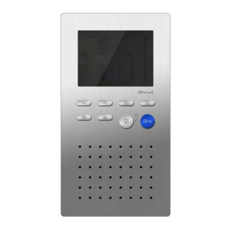
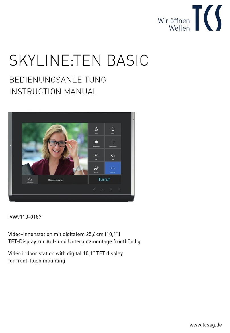
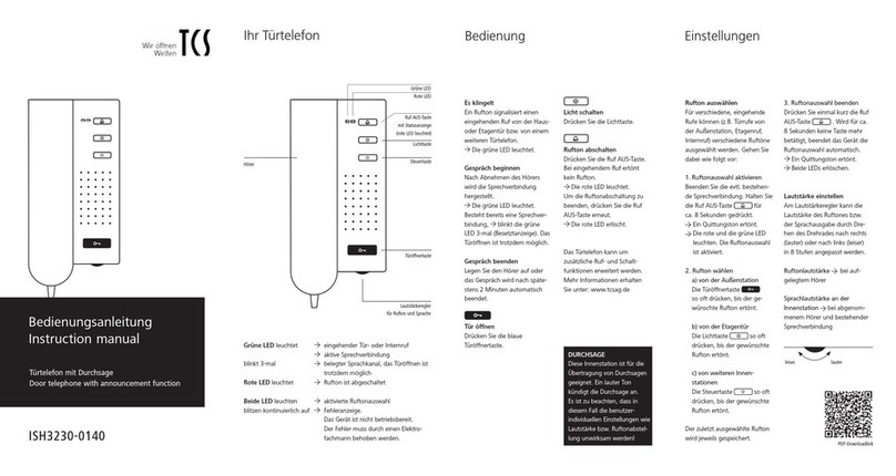
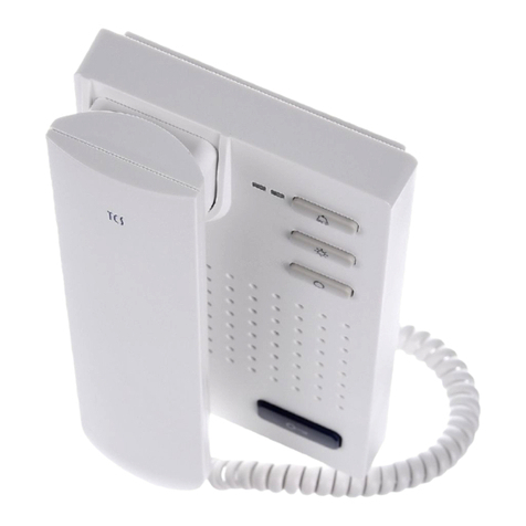
TCS AVC11010-0010 User manual

FAX: +49 (0) 41 94/ 9 88 129 PI_AVC11010-uk 1A
Product information
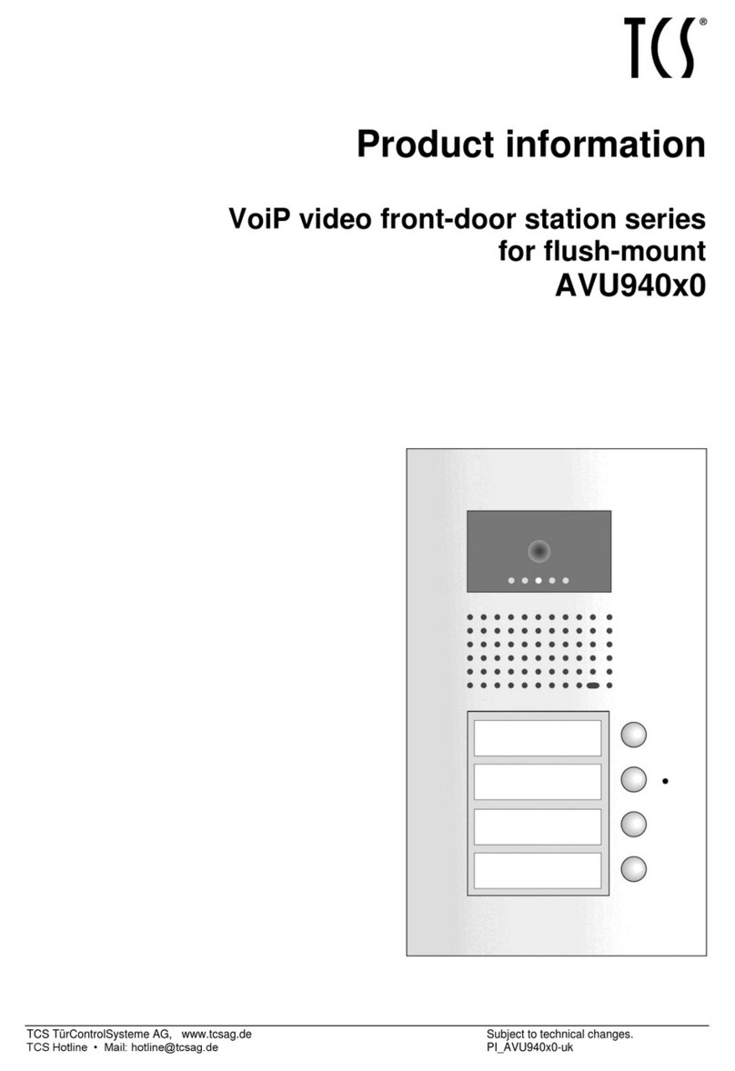
Video front-door station for video pack S-11010
(AVC11010-0010)

2 10/2012
FAX: +49 (0) 41 94/ 9 88 129 PI_AVC11010-uk 1A
Table of contents
Safety instructions.............................................................................................................2
General safety regulations ...............................................................................................2
Installation –protective measures....................................................................................3
Device overview.................................................................................................................3
Technical data....................................................................................................................4
Intended use.......................................................................................................................5
Short description...............................................................................................................5
Installation..........................................................................................................................5
Notes on the installation site ............................................................................................5
Mounting height................................................................................................................5
win:clip system.................................................................................................................5
Install the front-door station..............................................................................................6
Connect the lines...............................................................................................................7
General note ....................................................................................................................7
Connecting.......................................................................................................................7
5-wire special operation ...................................................................................................7
Commissioning..................................................................................................................7
Function check name plate illumination............................................................................7
Set volume of microphone and loudspeaker....................................................................8
Labelling the name plate...................................................................................................8
General information on the conduit in TCS video systems ...........................................8
6-wire operation................................................................................................................8
Principle loop resistance...............................................................................................9
Measure loop resistance...............................................................................................9
Cleaning............................................................................................................................10
Repair................................................................................................................................10
Exchange an indoor station –programming bell buttons................................................10
Conformity........................................................................................................................12
Information on disposal..................................................................................................12
Warranty...........................................................................................................................12
Service..............................................................................................................................12
Safety instructions
General safety regulations
!
Attention! Mounting, installation, commissioning and repair of electronic devices have
to be carried out only by qualified electricians. The latest accident prevention regula-
tions must be observed.
For working on systems with main connection of 230 V alternating voltage, the safety re-
quirements according to DIN VDE 0100 must be observed.
When installing TCS: BUS®systems, the general safety regulations for telecommunication
systems according to VDE 0800 must be observed. Inter alia:
separated conduit of heavy current and low current lines,
10/2012 3
FAX: +49 (0) 41 94/ 9 88 129 PI_AVC11010-uk 1A
minimum distance of 10 cm in case of a common conduit,
use of separators between heavy and low current lines within shared cable ducts,
use of standard communication lines, e.g. J-Y (St) Y with 0.8 mm diameter,
existing lines (modernisation) with deviating cross-sections can be used in compliance
with the loop resistance.
Installation –protective measures
!
With suitable measures to protect against lightning, it has to be ensured that a voltage
of 32 V DC is not exceeded at the connections.
Device overview
AVC, closed
Light sensor
Name plate glass
Infrared LEDs
Camera
Bell button
Loudspeaker
Microphone opening
Front panel
Infrared LEDs

4 10/2012
FAX: +49 (0) 41 94/ 9 88 129 PI_AVC11010-uk 1A
AVC, name plate glass removed
Technical data
Supply voltage: + 24 V ± 8 % (via power supply and control unit)
Housing: aluminium, anodised
Name plate glass: acrylic glass
Weight 380 g
Acceptable ambient temperature: - 20 °C ... + 50 °C
Input current: I(a) = 0.4 mA, I(P) = 140 mA
Max. input current: I(Pmax) = 156 mA
Camera
bw camera CCD sensor 380 TVL
Focal length: f = 3.6 mm
Light sensitivity: 0.2 Lux
Diagonal detection angle: 90°
Video output symmetric: 1 Vss BAS
Opening for win:clipTM
key
Cable gland
Connection terminals
V1, V2, M, P, R, b, a, G
b,
Connection name
plate illumination
Volume control
loudspeaker
Volume control
microphone
Attachement holes
1, 2
Name plate glass

10/2012 5
FAX: +49 (0) 41 94/ 9 88 129 PI_AVC11010-uk 1A
Intended use
The VPAK is a video front-door station in compact design (projection 16 mm) to be used
outdoors.
The stations are suitable for surface-mount.
Short description
win:clip™ principle
metal housing made of robust aluminium profiles
bell buttons made of metal with gold-plated, maintenance-free contacts
long-living and energy-saving name plate illumination with light sensor
shatter-proof name plate glass
acknowledgement tone when pressing the bell button
conversation time ex works: 56 seconds / adjustable with Service Device
volume and microphone sensitivity can be adjusted manually
plug-in memory to remove front-door stations which are identical in construction
R-terminal to connect an extended function door release
door release time at R-terminal ex works 3 seconds / adjustable with Service Device
door stand-by time (to control the short-term memory in indoor stations),
ex works: 56 seconds
voice connection during the door stand-by time
Installation
Notes on the installation site
For a good quality of the video image, the camera should not be oriented directly to-
wards solar radiation, strong sources of light, bright or strongly reflecting walls.
To guarantee a flawless function of the microphone, a distance of 5 cm must be en-
sured below the device!
Mounting height
The mounting height of the video front-door station is to be selected according to the de-
tection area of the camera (see illustration). Persons with an above-average height are
detected with a mounting height of 160 cm above the ground.
win:clip system
The device is equipped with the win:clip system to open and close the station without us-
ing any screws.

6 10/2012
FAX: +49 (0) 41 94/ 9 88 129 PI_AVC11010-uk 1A
Open the housing
1. Push the enclosed win:clip key into the small
opening within the loudspeaker cover.
Press the key into the opening until stop and keep
it in this position.
2. Push the name plate glass slightly upwards until it
jumps out.
3. Put out the glass carefully.
Remove the plug of the name plate illumination.
4. Remove the win:clip key.
Close the housing
1. Connect the plug of the name plate illumination
(see installation).
2. Push the enclosed win:clip key into the small
opening within the loudspeaker cover.
Press the key into the opening until stop and keep
it in this position.
3. Push the name plate glass under the loudspeaker
cover.
4. Press the name plate glass onto the device. Push
it slightly downwards until it snaps-in.
5. Remove the win:clip key.
Install the front-door station
1. Open the front-door station (see win:clip system).
2. Perforate carefully the foam cover on the backside of the device.
3. Insert the lines through the cable gland.
4. Install the front-door station at both attachment holes with suitable screws to the wall.
!
Please observe that no line is clamped below the spacer at the backside of the
front-door station.

10/2012 7
FAX: +49 (0) 41 94/ 9 88 129 PI_AVC11010-uk 1A
Connect the lines
General note
!
Connect the lines with the enclosed small screwdriver to prevent damaging the device.
Connecting
Strip the cable ends.
Connect the lines depending on the type of system and according to the wiring diagram
in the product information Video home:pack S-11010.
5-wire special operation
If there are only 5 wires available, you can use the
5-wire special operation.
The M-wire is to be connected to b via a bridge.
The slide switch in the video front-door station
must be set to “right”in 5-wire operation (”5W“).
Commissioning
!
First install the system completely, than connect it to the
main voltage!
Install all devices of the system completely.
V1 and V2 must not be connected to P-, a- or b-wire. When connecting the video wires
V1 (+) and V2 (-) please observe the polarity.
Check the a-, b- and P-wire against each other on short-circuits.
Switch ON the mains voltage.
Both LEDs of the video indoor station are blinking 3 x green. The system is ready to op-
erate.
Function check name plate illumination
The video front-door station is equipped with a light sensor. When the environment is suffi-
ciently illuminated, the name plate illumination turns OFF.
Check the function of the sensor by covering it. The name plate illumination turns ON.

8 10/2012
FAX: +49 (0) 41 94/ 9 88 129 PI_AVC11010-uk 1A
Set volume of microphone and loudspeaker
!
Use the enclosed small screwdriver for the setting!
Ex works the volumes are set on an average val-
ue. A modification is not always necessary.
Please observe when setting the values:
The amplification of the loudspeaker and the mi-
crophone cannot be set independently of one
another. Too high volumes cause a feedback
effect (whistling).
Volume control
Microphone
Regulate the
volume at the
indoor station
Loudspeaker
Regulate the
volume at the
front-door station
Labelling the name plate
Label the enclosed name plate foil (special foil).
We recommend to print out the name plates on a resistant special foil.
Order foils directly from TCS: writable polyester foil for name plates DIN A4.
Open the video front-door station.
Remove the name plate glass carefully.
Pull off the plug of the name plate illumina-
tion.
Open the name plate glass:
Insert the win:clip key into the small open-
ing and twist the key.
Put in the prepared foil and close the name
plate glass again.
General information on the conduit in TCS video systems
6-wire operation
The 6-wire operation is the standard operating mode. Video operation which use two sepa-
rated ground lines (b and M).
The conduit is determined by structural conditions and is only limited by length.
Please observe when selecting the length of the cable: the loop resistance must not
exceed a max. of 8 Ωat a-b and M-P (table 1).
If the loop resistance is > 8 Ω: plan multiple wiring of the strands (double twisted lines).
optinal strand or star formed wiring

10/2012 9
FAX: +49 (0) 41 94/ 9 88 129 PI_AVC11010-uk 1A
Do not use more than 20 video indoor stations per strand. In systems with more video
indoor stations plan to use video distributors (FVY1200, FVY1400).
Up to 64 front-door stations (16 from them video front-door stations) and an unlimited
number of indoor stations can be connected polarity-free (a/b) in one system (polarity-
free only with 6-wire operation). Therefore a suitable power supply and control unit is to
be used.
Table 1: Loop resistances
line length a-b/ M-P
in m
line diameter
0.6 mm
0.8 mm
loop resistance in Ω
10
1.28
0.71
20
2.55
1.43
30
3.83
2.14
40
5.10
2.86
50
6.38
3.57
60
7.65
4.29
70
5.00
80
5.71
90
6.43
100
7.14
Principle loop resistance
Measure loop resistance
None of the devices (AS, IS or FE) should be fur-
ther than 20 Ohm away from the power supply and
control unit (VS).
Rule:
Switch off the 230 V / 50 Hz of the VS.
Install a-b short-circuit at the VS.
Other devices are not disturbing the measure-
ment, they can stay connected.
Measure the resistance at a/b at the last IS or AS.
8 Ohm:
max. 65 m distance AS-VS by 0.6 mm diameter
max. 115 m distance AS-VS by 0.8 mm diameter
AS front-door station
VS power supply and control unit
IS indoor station
FE extended function
a, b short-circuit
here

10 10/2012
FAX: +49 (0) 41 94/ 9 88 129 PI_AVC11010-uk 1A
Cleaning
!
Avoid water from entering the device!
Do not use any abrasive detergents!
Clean the device with a dry or slightly wet cloth.
Remove stronger stains with a mild household cleaner.
Repair
Replacing an indoor station –programming bell buttons
Basics
All devices at the TCS:BUS have a unique serial number.
Programming a bell button means that the serial number of an indoor station is allocat-
ed to the bell button of a front-door station and is further stored within the EEPROM of
the front-door station.
Ensure that the new indoor station is connected to the TCS:BUS and the mains voltage
is switched ON (the operation LED at the power supply and control unit is ON). Further
ensure that the access to the flat is granted during the programming.
This instruction describes the allocation of a serial number to a bell button without set-
ting a programming lock. To deactivate a programming lock, a Service Device TCSK-
01or the configuration software configo™ is needed.
1
Initiate
Power supply and control unit
shortly press LED blinks
Programming mode of the system is switched ON
2
Delete a buttona)
Press until the delete-tone melody sounds 1)
release

10/2012 11
FAX: +49 (0) 41 94/ 9 88 129 PI_AVC11010-uk 1A
3
Programming via voice connection
Establish voice connection
to the front-door station
shortly press
the button
... a ring tone sounds at the front-door
and indoor station 1)
4
End
shortly press LED is ON
Programming mode of the system is switched OFF
a) Not necessary, if the bell buttons have not been programmed, compare product information of the front-door station.
1) If there sounds a Progsperr tone instead, the front-door station is equipped with a programming lock.
The programming lock can be deactivated only with the Service Device TCSK-01 or the configuration software
configo™.
Legend
Shortly press the button
Busy tone
Press button until
Negative acknowledgement tone
(bell button already programmed)
Release the button
LED blinks
Negative acknowledgement
signal (NoProg tone)
LED blinks quickly
Delete-tone melody
LED is ON
Prog2 tone (start of the pro-
gramming of the 2. serial no.)
Ring tone
Repeat
Progsperr tone
Further
Period of time (e.g. 6 s)
◄6s►

12 10/2012
FAX: +49 (0) 41 94/ 9 88 129 PI_AVC11010-uk 1A
Conformity
The device meets the requirements of the EU directive 2004/108/EG by respecting
the standards: EN 61000-6-3, EN 61000-6-1.
The declarations of conformity are available under www.tcsag.de, downloads, trade
information.
Information on disposal
The adjoining symbol shows, that the device has to be disposed separateley from
domestic waste. The material used are recyclable. Please do help protecting our
environment and dispose the device via a collecting point for electronic scrapp.
Dispose the parts of the packaging in collecting tanks for cardboard and paper
resp. plastics.
Warranty
We offer a simplified processing in case of warranty for electricians.
Please note our conditions of sale and delivery, download from www.tcsag.de, down-
loads, trade information.
Please contact the TCS HOTLINE.
Service
Please send your questions and inquiries to
Head quarters
TCS TürControlSysteme AG, Geschwister-Scholl-Str. 7, 39307 Genthin, Germany
Phone: +49 (0) 3933/879910, FAX: +49 (0 ) 3933/879911, Mail: info@ tcsag.de,
www.tcsag.de
Table of contents
Other TCS Intercom System manuals