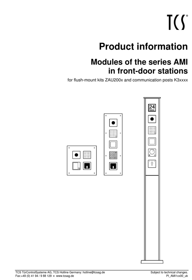
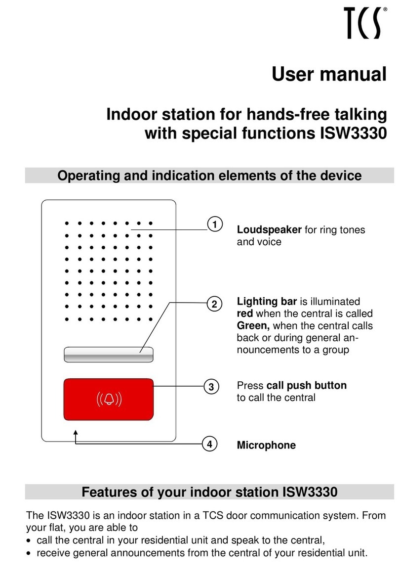
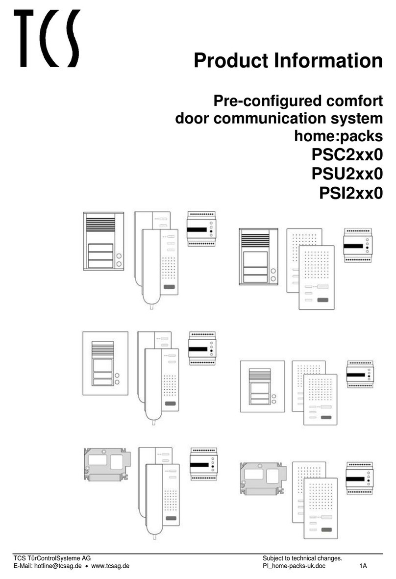
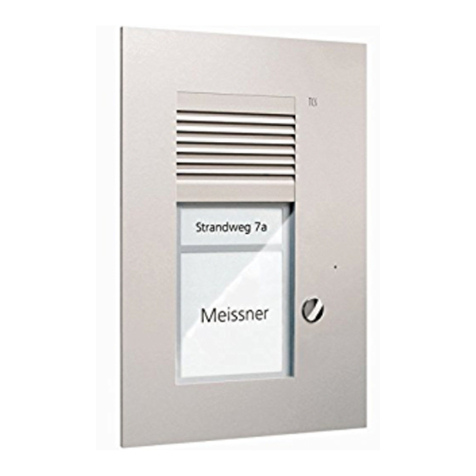
TCS AVU14 0 Series User manual

Product information
Front-door station series with colour-video
for flush-mount
AVU14xx0, 15xx0, 16xx0
TCS TürControlSysteme AG •Geschwister-Scholl-Str. 7 •39307 Genthin Subject to change without notice.
Phone.: +49 39 33 / 87 99 10 •Fax: +49 39 33 / 87 99 11 •www.tcs-germany.com PI_GB_AVU1_Art0016078_2v0.doc mi
2 05/2006
Table of contents
Safety notices ......................................................................................................................3
Scope of delivery .................................................................................................................3
General notes on the cabling in TCS video systems ...........................................................4
Terms for 5 wire and 6 wire operation ..............................................................................4
6 wire operation................................................................................................................4
5 wire operation................................................................................................................4
Technical data .....................................................................................................................5
Application ...........................................................................................................................6
Brief description ...................................................................................................................6
Basic functions .................................................................................................................6
Additional functions ..........................................................................................................6
Assembly .............................................................................................................................7
Notes................................................................................................................................7
Flush-mount box ...........................................................................................................7
Front-door station .........................................................................................................7
Installation location .......................................................................................................7
Installation height..........................................................................................................7
win:clip system .................................................................................................................8
Cable connection .................................................................................................................9
General notes...................................................................................................................9
Connection .......................................................................................................................9
Connection with 5-pole screw terminal.............................................................................9
Wiring example...............................................................................................................10
Connection diagram .......................................................................................................10
Video commissioning .........................................................................................................11
Microphone and loudspeaker volume setup ......................................................................11
Nameplate labelling ...........................................................................................................11
Programming of bell buttons ..............................................................................................12
Basic principle ................................................................................................................12
Programming with the Service Device............................................................................12
Programming steps legend ............................................................................................12
Programming state of a bell button ....................................................................................13
Testing ...........................................................................................................................13
Deleting the programming ..............................................................................................13
Programming a bell button.................................................................................................14
Method 1: In-house station not accessible .....................................................................14
Programming the other bell buttons:...........................................................................14
Method 2: In-house station accessible ...........................................................................15
Programming the other bell buttons:...........................................................................15
Programming an already programmed bell button.............................................................16
Basic principle ................................................................................................................16
Method 1: In-house station not accessible .....................................................................16
Programming the other already programmed bell buttons..........................................16
Method 2: In-house station accessible ...........................................................................17
Programming the other already programmed bell buttons..........................................17
Repair ................................................................................................................................18
Replacing the EEPROM memory...................................................................................18
Cleaning.............................................................................................................................18
Service...............................................................................................................................18
TCS TürControlSysteme AG •Geschwister-Scholl-Str. 7 •39307 Genthin Subject to change without notice.
Phone.: +49 39 33 / 87 99 10 •Fax: +49 39 33 / 87 99 11 •www.tcs-germany.com PI_GB_AVU1_Art0016078_2v0.doc mi
3 05/2006
Safety notices
!Assembly, installation, and commissioning must only be carried out by a qualified elec-
trician!
For work on systems with 230 V AC mains voltage the safety requirements of DIN VDE
0100 must be observed.
When installing TCS:BUS systems the general safety rules for telecommunication systems
in accordance with VDE 0800 must be observed:
• separate cabling for high and low voltage lines,
• minimum distance of 10 cm for joint cabling arrangements,
• use of separators between high and low voltage lines in joint cable ducts,
• use of standard telecommunication cables, e. g. J-Y (St) Y with 0.8 mm² cross section,
• existing cables (modernisation) with different cross sections may be used whilst taking
account of the loop resistance.
!Suitable lightning protection must ensure that a voltage of 32 V DC will not be ex-
ceeded at the TCS:BUS wires a and b.
Scope of delivery
1 x AVU14XX0, 15XX0, 16XX0 (incl. concealed box)
1 x win:clip key
1 x screwdriver with round handle
1 x key for hexagon socket screws DIN911 (ISO2936)
connection terminal 5-pole
name plates
hexagon socket screws (for attaching the device in the concealed box, 2 per button row)
product information
programming table
TCS TürControlSysteme AG •Geschwister-Scholl-Str. 7 •39307 Genthin Subject to change without notice.
Phone.: +49 39 33 / 87 99 10 •Fax: +49 39 33 / 87 99 11 •www.tcs-germany.com PI_GB_AVU1_Art0016078_2v0.doc mi
4 05/2006
General notes on the cabling in TCS video systems
Terms for 5 wire and 6 wire operation
6 wire operation standard operating mode. Video operation where two separate
earths (b and M) are being used.
5 wire operation special operating mode. Video operation where b and M are joined to
a single earth.
6 wire operation
The cabling depends on the building situation and is only limited by its length.
• When selecting the cable length consider: the loop resistance M-P must be max. 8 Ω
(table 1).
• For loop resistance > 8 Ω: provide for multiple wiring of the lines (twisted pairs).
• choice of line or star wiring
• Do not use more than 6 video in-house stations per line. For systems with more video
in-house stations provide for the use of video distributors (VT02, VT04).
• up to 64 front-door stations and an almost unlimited number of in-house stations can be
connected polarity-free (a/b) to a system. (use suitable power supply and control unit.)
Table 1: Loop resistances
Line diameterLine length M-P
in m 0.6 mm 0.8 mm
Loop resistance in Ω
10 1.22 0.69
20 2.45 1.38
30 3.67 2.07
40 4.90 2.76
50 6.12 3.44
60 7.35 4.13
70 4.82
80 5.51
90 6.20
100 6.89
5 wire operation
Number of monitor
s
in the system
max. permissible loop
resistance in Ω
24 4,8
12 6,3
6 8
TCS TürControlSysteme AG •Geschwister-Scholl-Str. 7 •39307 Genthin Subject to change without notice.
Phone.: +49 39 33 / 87 99 10 •Fax: +49 39 33 / 87 99 11 •www.tcs-germany.com PI_GB_AVU1_Art0016078_2v0.doc mi
5 05/2006
Device overview
color camera
loudspeaker
cover
Shown is the VPUK01/1,
without name plate glass condensate
drainage
attachment
hole 2: below
reflective foil
opening for win:clip
key
loudspeaker attachment
hole 1
EEPROM connection
Service Device
microphone
v
o
lume control
loudspeaker
volume control bell button
reflective foil microphone
front panel
Technical data
Supply voltage: 24 V ± 8 % (via power supply and control unit)
Case: aluminium, anodised
Name plate glass: plexiglass
Operating temperature range: -20°C to 50°C
Input current (one column): I(a) = 0.4 mA, I(P) = 120 mA standby
Input current (two columns): I(a) = 0.8 mA, I(P) = 135 mA standby
Input current (three columns): I(a) = 1.2 mA, I(P) = 150 mA standby
Maximum input current (one column): I(Pmax) = 135 mA
Maximum input current (two columns): I(Pmax) = 150 mA
Maximum input current (two columns): I(Pmax) = 165 mA
TCS TürControlSysteme AG •Geschwister-Scholl-Str. 7 •39307 Genthin Subject to change without notice.
Phone.: +49 39 33 / 87 99 10 •Fax: +49 39 33 / 87 99 11 •www.tcs-germany.com PI_GB_AVU1_Art0016078_2v0.doc mi
6 05/2006
camera features colour-camera: Sony CCD-sensor 420 TVL Super HAD
photo sensitivity: 0.2 Lux
automatic day/night switch
focal length: f = 3.6
diagonal capture: 90°
video output 1 Vpp composite video balanced
based on the TCS-video system in a 6-wire technique
Application
• AVU are video front-door stations for external use.
• They are characterised by their space-saving design.
• The housing is fitted with the win:clip system.
• The front panel consists of 3 mm strong aluminium.
• Universal assembly: Flush or in cavity wall.
Brief description
Basic functions
Bell buttons
• Operating a programmed bell button triggers a ringing
tone at the in-house station.
• Operating an unprogrammed bell button triggers the
light switch function in the power supply and control
unit.
• When operating a bell button an acknowledgement
tone sounds.
Saving the bell button alloca-
tions in the front-door station
All programmed data (serial numbers and parameters)
are stored in the EEPROM. If the front-door station re-
quires replacement, the EEPROM board can be removed
from the programmed front-door station and inserted into
the new front-door station of identical design.
Camera colour-camera, image activation constantly enabled
(video signal always connected)
Additional functions
Name plate illumination Via LED, P-wire connection required.
connection for Service Device
Allocation of serial number to
bell buttons
2
additional switching signal Use a combining device BRE2.
TCS TürControlSysteme AG •Geschwister-Scholl-Str. 7 •39307 Genthin Subject to change without notice.
Phone.: +49 39 33 / 87 99 10 •Fax: +49 39 33 / 87 99 11 •www.tcs-germany.com PI_GB_AVU1_Art0016078_2v0.doc mi
7 05/2006
Assembly
Notes
Flush-mount box
• Feed the connection cable through the cable duct in the flush-mount box and attach it to
the wall using suitable screws.
• The front-door station profile should fit flush with the base.
Front-door station
• Attach the front-door station from the attachment holes to the stud bolts in the flush-
mount box using the hexagonal socket screws supplied.
• Take care not to over-tighten the screws. This would distort the case so that the loud-
speaker cover and name plate glass could no longer be inserted or removed.
Installation location
To achieve a good video quality the camera
must not point directly at:
• sunlight,
• strong sources of light,
• bright or strongly reflecting walls.
Installation height
The installation height for the video front-
door station must be selected under consid-
eration of the field of capture of the camera
(see figure). Persons with average body
height are best captured with an installation
height of 160 cm above floor level.
3.6 mm lens
90 ° diagonal capture angle
TCS TürControlSysteme AG •Geschwister-Scholl-Str. 7 •39307 Genthin Subject to change without notice.
Phone.: +49 39 33 / 87 99 10 •Fax: +49 39 33 / 87 99 11 •www.tcs-germany.com PI_GB_AVU1_Art0016078_2v0.doc mi
8 05/2006
win:clip system
The device is fitted with the win:clip system which enables opening and closing without the
use of screws.
Opening the housing
1. Insert the win:clip key supplied into the small o-
pening in the front panel.
Push the key into the opening up to the stop and
hold it in that position.
2. Slide the name plate glass slightly upwards until it
jumps out.
3. Remove the glass.
4. Remove the win:clip key.
Closing the housing
1. Insert the win:clip key supplied into the small o-
pening at the front panel.
Push the key into the opening up to the stop and
hold it in that position.
2. Slide the name plate glass under the front panel.
3. Press the name plate glass onto the device and
slide it down slightly until it engages.
4. Remove the win:clip key.
!Never seal the device using silicon! Condensate must be allowed to drain and evapo-
rate.
TCS TürControlSysteme AG •Geschwister-Scholl-Str. 7 •39307 Genthin Subject to change without notice.
Phone.: +49 39 33 / 87 99 10 •Fax: +49 39 33 / 87 99 11 •www.tcs-germany.com PI_GB_AVU1_Art0016078_2v0.doc mi
9 05/2006
Cable connection
General notes
!Use the small screwdriver supplied to connect the lines and prevent damage to the
device.
Connection
1. Strip the insulation from the line ends.
2. Connect the lines, depending on system type, in accordance with the wiring example.
Connection with 5-pole screw terminal
Connect with terminal 1:
• TCS:BUS, P and video cables,
• optionally: FAA1100 (TOER1)
to P.
Connect with terminal 2:
• optionally: FAA1100 (TOER1)
to R.
Pluggable screw terminal 1:
TCS:BUS and video connection
Pluggable screw
terminal 2
Back of front-door station
TCS TürControlSysteme AG •Geschwister-Scholl-Str. 7 •39307 Genthin Subject to change without notice.
Phone.: +49 39 33 / 87 99 10 •Fax: +49 39 33 / 87 99 11 •www.tcs-germany.com PI_GB_AVU1_Art0016078_2v0.doc mi
10 05/2006
Wiring example
Additional video in-house stations
Set end resistor
in the last video
unit of a line
floor-
switch
button
floor-
switch
button
Connection diagram
TCS TürControlSysteme AG •Geschwister-Scholl-Str. 7 •39307 Genthin Subject to change without notice.
Phone.: +49 39 33 / 87 99 10 •Fax: +49 39 33 / 87 99 11 •www.tcs-germany.com PI_GB_AVU1_Art0016078_2v0.doc mi
11 05/2006
Video commissioning
!
First fully install the system, then connect power!
• V1 and V2 must never - not even temporarily - be connected to the P, a or b wires.
Such a connection would destroy the device.
• When connecting the video wires V1 (+) and V2 (-) the polarity must be observed.
If the image is distorted after commissioning, switch off the device and replace the
wires for the video signal.
Microphone and loudspeaker volume setup
!For adjustments use the small screwdriver supplied!
Volume control
microphone
In-house station
volume
adjustment
loudspeaker
Front-door station
volume
adjustment
The volumes have been set to an average value
at factory. A modification may not always be
necessary.
When adjusting please note:
The amplification of loudspeaker and microphone
cannot be set independently from each other.
Too great volume will cause a feedback effect
(whistling).
Nameplate labelling
The templates are available on our website www.tcs-
germany.com \ English \ Downloads \ System and
technology basics \ Product installation and use \ la-
belling of the nameplate
1. Enter the desired name into the template. Print the
name plate on the special film* and cut it to size.
Alternatively write on the plates supplied.
2. Insert the cut plates from above into the pockets in
the name plate glass. Use the insertion aid (plastic
plate, supplied) to assist with opening the pockets.
The inserted name plates now protrude 2 mm at the
top of the pocket and can therefore be easily removed
for replacement purposes.
* We recommend to print the name plates on a durable special film.
The film can be ordered directly from TCS: Writable polyester film
for name plates DIN A4.
name plate
pocket for
name plate
name plate glass
TCS TürControlSysteme AG •Geschwister-Scholl-Str. 7 •39307 Genthin Subject to change without notice.
Phone.: +49 39 33 / 87 99 10 •Fax: +49 39 33 / 87 99 11 •www.tcs-germany.com PI_GB_AVU1_Art0016078_2v0.doc mi
12 05/2006
Programming of bell buttons
Basic principle
All devices at the TCS:BUS have a unique serial number. During programming this serial
number is transferred to the front-door station and linked to the bell button.
Programming with the Service Device
Utilise the simple 1 person programming with the TCS Service Device. You will not need
access to the in-house stations in the flats. The voltage supply is provided by connecting
the Service Device to the TCS:BUS. For more on the TCS Service Sevice see: www.tcs-
germany.de
If you do not have the Service Device, you can also program manually.
Programming steps legend
briefly press key LED flashes slowly
press key until
LED flashes rapidly
release key
ring tone
NoProg tone
continue
wait until Prog2 tone
Delation tone Progsperr tone
TCS TürControlSysteme AG •Geschwister-Scholl-Str. 7 •39307 Genthin Subject to change without notice.
Phone.: +49 39 33 / 87 99 10 •Fax: +49 39 33 / 87 99 11 •www.tcs-germany.com PI_GB_AVU1_Art0016078_2v0.doc mi
13 05/2006
Programming state of a bell button
The front-door stations are supplied un-programmed.
The programming state can be checked as follows:
Testing
Noprog tone
press briefly ring tone
bell button
un-programmed
bell button
programmed
Before a pre-programmed bell button can be re-programmed, the programming must be
deleted.
Deleting the programming
1
Press briefly LED flashes
programming
mode
of system
switched on
2
Press deletion tone release
until sounds1),
bell button
deleted
3
Press briefly LED flashes
no more
programming
mode
of system
switched off
1) If Progsperr ton sounds the programming block is active. It can be removed by the service device TCSK-01 only.
TCS TürControlSysteme AG •Geschwister-Scholl-Str. 7 •39307 Genthin Subject to change without notice.
Phone.: +49 39 33 / 87 99 10 •Fax: +49 39 33 / 87 99 11 •www.tcs-germany.com PI_GB_AVU1_Art0016078_2v0.doc mi
14 05/2006
Programming a bell button
Connect the in-house station to the TCS:BUS.
Use one of these two methods.
Method 1: In-house station not accessible
1LED illuminates
Press briefly LED flashes
programming
mode
of system
switched on
2
Floor-switch button within 3 sec:
press 1 sec, until bell rings - release - press 1 sec until bell rings - release.
3
Press briefly ring tone sounds at front-door and in-house station1)
bell button
programmed
4
Press briefly LED illuminates
programming
mode
of system
switched off
Programming the other bell buttons:
• Step 1
• repeat steps 2and 3each time
• complete the programming of all buttons with step 4
TCS TürControlSysteme AG •Geschwister-Scholl-Str. 7 •39307 Genthin Subject to change without notice.
Phone.: +49 39 33 / 87 99 10 •Fax: +49 39 33 / 87 99 11 •www.tcs-germany.com PI_GB_AVU1_Art0016078_2v0.doc mi
15 05/2006
Method 2: In-house station accessible
1 LED illuminates
Press briefly LED flashes
programming
mode
of system
switched on
2
Lift handset
2) press briefly, replace handset
at in-house station ring tone sounds at in-house station
at front-door and in-house station1).
bell button
programmed
3
Press briefly LED illuminates
programming
mode
of system
switched off
Programming the other bell buttons:
• Step 1
• repeat step 2each time for additional bell buttons where necessary
• complete the programming of all buttons with step 3
2) In-house stations without handset: to establish a voice communication press the speak button (resp. switch button
speak / listen).
TCS TürControlSysteme AG •Geschwister-Scholl-Str. 7 •39307 Genthin Subject to change without notice.
Phone.: +49 39 33 / 87 99 10 •Fax: +49 39 33 / 87 99 11 •www.tcs-germany.com PI_GB_AVU1_Art0016078_2v0.doc mi
16 05/2006
Programming an already programmed bell button
Basic principle
A bell button can be linked to two serial numbers (of two in-house stations). It is then pos-
sible to have two different in-house stations ring at the same time.
Connect the in-house stations to the TCS:BUS.
Use one of these two methods.
Method 1: In-house station not accessible
1 LED illuminates
Press briefly LED flashes
programming
mode
of system
switched on
2
Floor-switch button within 3 sec:
press 1 sec, until bell rings - release - press 1 sec until bell rings - release.
3
Press ... and ... and ring tone sounds release
until Noprog tone at front-door and
Prog2 tone sounds1)... sounds in-house station.
bell button
programmed
4
Press briefly LED illuminates
programming
mode
of system
switched off
Programming the other already programmed bell buttons
• Step 1
• repeat steps 2and 3each time
• complete the programming of all buttons with step 4
TCS TürControlSysteme AG •Geschwister-Scholl-Str. 7 •39307 Genthin Subject to change without notice.
Phone.: +49 39 33 / 87 99 10 •Fax: +49 39 33 / 87 99 11 •www.tcs-germany.com PI_GB_AVU1_Art0016078_2v0.doc mi
17 05/2006
Method 2: In-house station accessible
1 LED illuminates
Press briefly LED flashes
programming
mode
of system
switched on
2
Lift handset 2) Press until ...and ... and ring tone release replace
at the Prog2 tone Noprog tone sounds at handset
in-house sounds1) sounds front-door and at in-house
station. … in-house station. station.
bell button
programmed
3
press briefly LED illuminates
programming
mode
of system
switched off
Programming the other already programmed bell buttons
• Step 1
• repeat step 2each time for additional bell buttons where necessary
• complete the programming of all buttons with step 3
Note
Repeated programming of an already programmed bell button always only changes the
second serial number. If you want to change the first programmed serial number, you have
to delete both serial numbers and then re-program both serial numbers.
TCS TürControlSysteme AG •Geschwister-Scholl-Str. 7 •39307 Genthin Subject to change without notice.
Phone.: +49 39 33 / 87 99 10 •Fax: +49 39 33 / 87 99 11 •www.tcs-germany.com PI_GB_AVU1_Art0016078_2v0.doc mi
18 05/2006
Repair
Replacing the EEPROM memory
All programmed data, like serial numbers and parameters, are stored in the EEPROM. If
the front-door station requires replacement, the EEPROM board can be removed from the
programmed front-door station and inserted into the new front-door station of identical de-
sign.
• Open the case.
• Pull the small PCB off the electronic board.
• Plug the EEPROM board onto the pins in the new un-programmed front-door station.
Take care that all four poles of the plug are inserted into the jack of the small PCB and
that the component side is visible.
• After replacement all programming is available again.
Cleaning
!Avoid water entering the device!
Do not use any aggressive or abrasive cleaning agents!
Clean the device using a dry or slightly moist cloth.
More persistent dirt can be removed using a mild household cleaner.
Service
Contact your local sales representative or
www.tcs-germany.com
TCS TürControlSysteme AG •Geschwister-Scholl-Str. 7 •39307 Genthin Subject to change without notice.
Phone.: +49 39 33 / 87 99 10 •Fax: +49 39 33 / 87 99 11 •www.tcs-germany.com PI_GB_AVU1_Art0016078_2v0.doc mi
This manual suits for next models
20
Table of contents
Other TCS Intercom System manuals

TCS
TCS ECOOS:FIVE User manual

TCS
TCS Carus Origo CAI2010 User manual

TCS
TCS ISH3022 User manual

TCS
TCS Carus Adapto User manual

TCS
TCS PSC2 0 Series User manual

TCS
TCS ISH3022-0140 User manual

TCS
TCS IVX9001-0140 User manual

TCS
TCS IVW9011-0261 User manual

TCS
TCS ASX1300 -0010 Series User manual

TCS
TCS Tasta Series Instruction manual