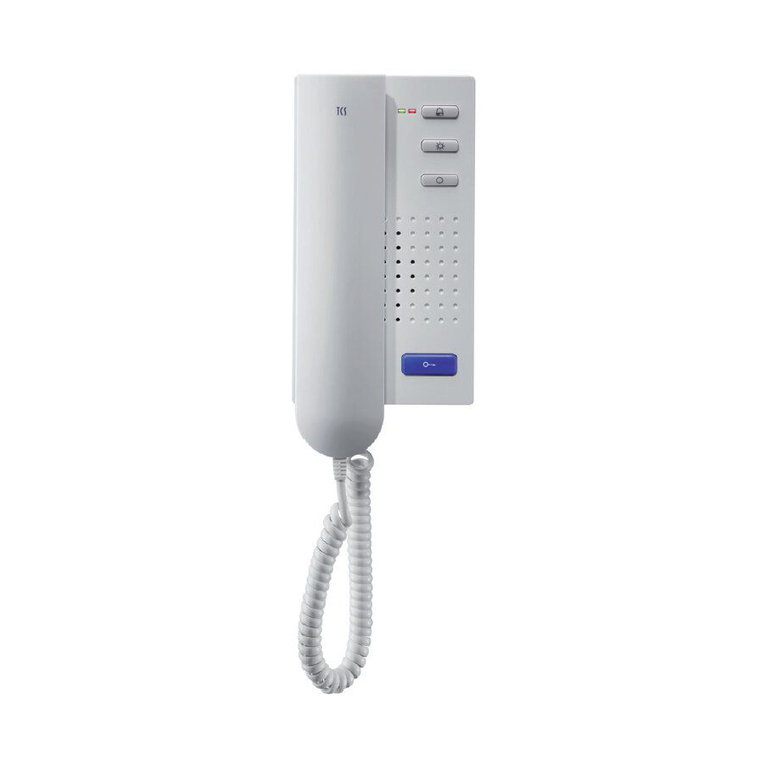
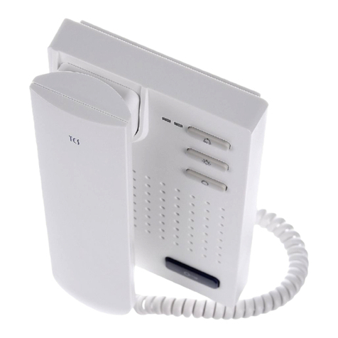
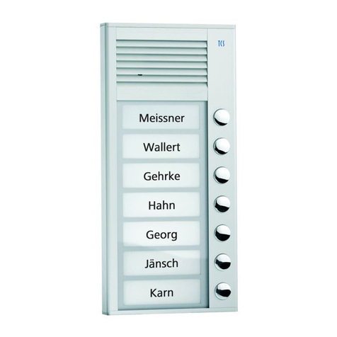
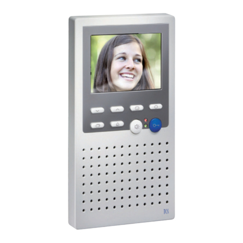
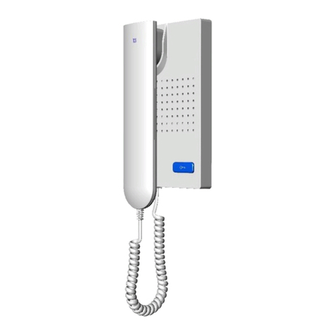
TCS IVH3222 User manual

TCS TürControlSysteme AG, TCS Hotline Germany: +49 (0) 4194 9881-188 Subject to technical changes.
E-Mail: hotline@tcsag.de, www.tcsag.de PI_IVH3222-0140_uk 3 A
Product information
Object video indoor station
IVH3222

2 02/2015
TCS TürControlSysteme AG, TCS Hotline Germany: +49 (0) 4194 9881-188 Subject to technical changes.
E-Mail: hotline@tcsag.de, www.tcsag.de PI_IVH3222-0140_uk 3 A
Table of contents
Scope of delivery...............................................................................................................3
Safety instructions.............................................................................................................3
General safety regulations ...............................................................................................3
Installation –protective measures....................................................................................3
Device overview.................................................................................................................4
Indication and operation elements...................................................................................4
Intended use.......................................................................................................................5
Max. number IVH3222 i 6-wire operation.........................................................................5
Short description...............................................................................................................5
Technical data....................................................................................................................6
Installation..........................................................................................................................6
mounting height................................................................................................................6
Install the lower cover.......................................................................................................6
Connect the lines..............................................................................................................7
Place matching resistor....................................................................................................7
Close the device...............................................................................................................7
Connect the handset........................................................................................................7
Open the device...............................................................................................................8
Install a built-in call relay TRE1-EB/1............................................................................8
Connect the lines..............................................................................................................9
Connecting lines...........................................................................................................9
Wiring diagram..............................................................................................................9
Connection diagram.......................................................................................................10
Commissioning................................................................................................................10
Configuration ...................................................................................................................10
AS-address dependent image activation........................................................................10
Factory settings..............................................................................................................10
Pre-adjusted times......................................................................................................11
Configuration options .....................................................................................................11
Programming with the Service Device TCSK-01...........................................................11
Settings.............................................................................................................................12
Switch ON/OFF the ring tone mute with the call OFF-button .........................................12
Set the ring tone volume ................................................................................................12
General information on the conduit in TCS video systems .........................................12
6-wire operation..............................................................................................................12
Repair................................................................................................................................13
FAQ................................................................................................................................14
Cleaning............................................................................................................................16
Information on disposal ..................................................................................................16
Warranty...........................................................................................................................16
Spare parts.......................................................................................................................16
Service..............................................................................................................................16

02/2015 3
TCS TürControlSysteme AG, TCS Hotline Germany: +49 (0) 4194 9881-188 Subject to technical changes.
E-Mail: hotline@tcsag.de, www.tcsag.de PI_IVH3222-0140_uk 3 A
Scope of delivery
1 x indoor station IVH3222: upper cover, lower cover, handset with handset cord
product information
instruction manual
Safety instructions
General safety regulations
!
Attention! Mounting, installation, commissioning and repair of electronic devices have
to be carried out only by qualified electricians. Thus, the current standards for the in-
stallation of door communication systems must be observed.
For working on systems with main connection of 230 V alternating voltage, the safety regu-
lations according to DIN VDE 0100 must be observed.
When installing TCS:BUS systems the general safety regulations for telecommunication
systems according to VDE 0800 must be observed. Inter alia:
separated guidance of heavy and low current lines,
minimum distance of 10 cm in case of a common conduit,
use of separators between heavy and low current lines within shared cable ducts,
use of standard telecommunication lines, e.g. J-Y (St) Y with 0.8 mm diameter,
already existing lines (modernisation) with deviating cross-sections can be used in
compliance with the loop resistance.
Installation –protective measures
!
With suitable measures to protect against lightning, it has to be ensured that a voltage
of each 32 V DC is not exceeded at the connections.

4 02/2015
TCS TürControlSysteme AG, TCS Hotline Germany: +49 (0) 4194 9881-188 Subject to technical changes.
E-Mail: hotline@tcsag.de, www.tcsag.de PI_IVH3222-0140_uk 3 A
Device overview
Indication and operation elements
handset
speaking to the door
end communication
○
function key
trigger light switch function
call the central (send control function 8)
image activation (and switch-over)
door release button
open the door
trigger the light switch function when the handset is
hung up*
* if light switch function is activated in the front.door station
loudspeaker
door release
button
handset with
handset cord
ring tone volume control
function key
screen
call OFF-button

02/2015 5
TCS TürControlSysteme AG, TCS Hotline Germany: +49 (0) 4194 9881-188 Subject to technical changes.
E-Mail: hotline@tcsag.de, www.tcsag.de PI_IVH3222-0140_uk 3 A
Intended use
The IVH3222 is a video indoor station for duplex communication with handset for the
TCS:BUS.
It can be used for the operation within TCS vidio systems and combined audio / video
systems in the commercial sector.
It is suitable for surface-mount above a flush-mount socket.
Max. number IVH3222 in 6-wire operation
When using power supply
and control unit
Max. number
of IVH3222
VBVS05, 1 line
20
BVS20 + NGV1011,
1 strand
80
AS front-door station
VS power supply and control unit
IS indoor station
Note: The max. number of front-door stations which
can be connected is limited. Details are described in
the product information of the device!
Short description
blue door release button
function key for switching lights, control function, image activation (can be configured
with the configuration software configo™)
ring tone volume can be adjusted continuously (via rotary control)
acoustic ring tone distinction: door calls from 2 front-door stations, flat door call (floor
bell) and internal call
7 ring tones can be selected (selection via configo™)
ring tone mute (via slide switch)
brightness/contrast can be adjusted manually in 8 steps und continuously with configo™
one parallel call can be activated via Service Device TCSK-01 or configo™
calling a central can be realised with the control function 8 (with configured function key)
audio privacy function
pluggable handset cord
lower cover with plugged screw terminal can be pre-installed
configuration software configo™ can be used for an easy system configuration at PC
with automatic detection of device type and serial number
tested according to EN 50486
housing made of antistatic and recyclable plastics

6 02/2015
TCS TürControlSysteme AG, TCS Hotline Germany: +49 (0) 4194 9881-188 Subject to technical changes.
E-Mail: hotline@tcsag.de, www.tcsag.de PI_IVH3222-0140_uk 3 A
Technical data
supply voltage: +24 V ±8 % (power supply and control unit)
housing: plastics, white
dimensions (in mm): H 250 x W 100 x D 50/28 (with/without handset)
weight 410 g
acceptable ambient temperature: 0 °C …+40 °C
degree of protection: IP30
input current: I(a) = 0.2 mA, I(P) = 4 mA
max. input current: I(Pmax) = 90 mA
video module TFT color module
screen diagonal: 8.9 cm (3.5 inch)
resolution: 320 x 240 pixel, RGB
video signal input: symmetric 1 Vss FBAS,
Video 6-wire technique necessary!
Installation
!
Attention!
Video indoor stations have to be (de-)installed only voltage-free!
!
Please ensure not to overtighten the screws when installing the lower cover on uneven
surfaces. Over tighten the screws might be deforming the lower cover. As a result the
upper cover cannot be snapped-on to the lower cover or the save contact between
lower and upper cover might be affected.
mounting height
For an optimum viewing angle we recommend a mounting
height of 1.6 meters (upper egde of the device over the
ground).
Install the lower cover
For placing the connection cables without any problems, a
flush-mounted socket must be installed behind the device.
Position the flush-mounted socket below the cable con-
duit.
Install the lower cover with at least three suitable
screws to the wall: Attachment holes accordingly to the
illustration to the wall (A) or on the flush-mount socket
(B).
Screws are not enclosed in the
delivery.
position
flush-mount
socket
AWall fixing
BFixing on the
flush-mount
socket

02/2015 7
TCS TürControlSysteme AG, TCS Hotline Germany: +49 (0) 4194 9881-188 Subject to technical changes.
E-Mail: hotline@tcsag.de, www.tcsag.de PI_IVH3222-0140_uk 3 A
Connect the lines
Minimize the length of the lines above the
lower cover to place the lines without any
problems and do not clamp the lines when
snapping-on the upper cover.
Connect the lines according to the labeling
(in the lower cover): a b E P M V1 V2 (from
the bottom to the top),
floor push button to a and E.
See wiring diagram on page 9
Place matching resistor
The video indoor station IVH3222 is not suitable
for the operation at the end of a strand ex
works. Switch in position OFF.
For the operation with further up streamed
video indoor stations slide the switch in posi-
tion ON.
Close the device
Set on the upper cover at both adjustment
increments of the lower cover (1).
Snap-on the upper cover below with slight
pressure (2)
Connect the handset
Plug the Western socket of the handset cord
into the socket at the underside of the tele-
phone.
floor push button
2
1
ON
OFF

8 02/2015
TCS TürControlSysteme AG, TCS Hotline Germany: +49 (0) 4194 9881-188 Subject to technical changes.
E-Mail: hotline@tcsag.de, www.tcsag.de PI_IVH3222-0140_uk 3 A
Open the device
Remove the handset cord.
There is a rectangular release opening at the
underside of the device. Insert a small
screwdriver straight and with slight pressure
into this opening.
The upper cover can be removed at the un-
derside (1).
Lift the upper cover out of the two upper ad-
justment increments (2).
Install a built-in call relay TRE1-EB/1
1
2
Plug on both
contacts.
b
a

02/2015 9
TCS TürControlSysteme AG, TCS Hotline Germany: +49 (0) 4194 9881-188 Subject to technical changes.
E-Mail: hotline@tcsag.de, www.tcsag.de PI_IVH3222-0140_uk 3 A
Connect the lines
Connecting lines
acceptable cross-section (diameter)
0.08 … 0.82 mm2(Ø 0.32 … 1.0 mm)
max. number of wires per terminal contact
each 2 x 0.8 mm, 3 x 0.6 mm
!
Further wires have to be connected with auxiliar terminals!
Use only connecting lines with the same diameter within one terminal contact.
Wiring diagram
Place the matching
resistor when the de-
vice is installed at the
end of the TCS:BUS
video strand.

10 02/2015
TCS TürControlSysteme AG, TCS Hotline Germany: +49 (0) 4194 9881-188 Subject to technical changes.
E-Mail: hotline@tcsag.de, www.tcsag.de PI_IVH3222-0140_uk 3 A
Connection diagram
Commissioning
!
First install the system completely, than connect it to the mains voltage!
Install the devices of the system completely.
V1 and V2 must not be connected with the P-, a- or b-wire.
When connecting the video wires V1 (+) and V2 (−) the polarity must be observed.
Check the a-, b- and P-wire against each other for short-circuits.
Switch on the main voltage.
Configuration
AS-address dependent image activation
If there are also front-door stations without cameras in a system with IVH3222 and video
front-door stations, the image is not activated when the IVH3222 is called by an audio
front-door station.
To guarantee this function, the possible AS addresses are separated into two sections:
AS address
0 –31*
reserved for video front-door
stations
the image is activated in case of a
door call (from max. 16 video front-
door stations)
AS address
as of 32*
free, for front-door stations
without camera
the image is not activated in case of a
door call
*) The video AS border cannot be changed.
Factory settings
The device is equipped with an EEPROM which stores the following basic settings ex
works:
serial number for parallel call
1000000
function key
image button

02/2015 11
TCS TürControlSysteme AG, TCS Hotline Germany: +49 (0) 4194 9881-188 Subject to technical changes.
E-Mail: hotline@tcsag.de, www.tcsag.de PI_IVH3222-0140_uk 3 A
Pre-adjusted times
communication time
max. 2 min
image switch time
80 sec
internal standby time
around 30 s
timeout call OFF (with TCSK-01)
4 min
Configuration options
Function
manually
TCSK-01
configoTM
as of version 1.8.x.x
function key image button
–
x
x
function key control function 8
–
x
x
function key switching lights
–
x
x
ring tone volume
x
–
–
select ring tones for 2 door calls, internal
calls and floor calls
–
–
x
parallel allocation
–
x
x
image parameter (color shade, brightness,
contrast)
–
–
x
image parameter (brightness, contrast)
x
–
x
image parameter (color shade)
–
–
x
change audio AS border*
–
–
–
Reload factory settings
–
–
x
* The audio AS border is fixed on 15 (door call 1: 0 to 15 door call 2 16 to 63).
Programming with the Service Device TCSK-01
The indoor station is acting as a telephone.
Use the command “8“ for configuring (see product information Service Device TCSK-
01).
search telephones
activate parallel call
deactivate parallel call
control function 8
configure the function key as image button
configure the function key as light switch button
0

12 02/2015
TCS TürControlSysteme AG, TCS Hotline Germany: +49 (0) 4194 9881-188 Subject to technical changes.
E-Mail: hotline@tcsag.de, www.tcsag.de PI_IVH3222-0140_uk 3 A
ser. no. = the serial number of the indoor station that is to be configured anew
ParSNo.= the serial number of the indoor station, to which the new configured indoor station is allocated
Settings
Switch ON/OFF the ring tone mute with the call
OFF-button
switch ring tone mute ON: slide the call OFF-
button (right side of the device) upwards
switch OFF ring tone mute: slide the call OFF-
button downwards (symbol call OFF)
Set the ring tone volume
The ring tone volume can be adjusted continuously.
Set brightness/contrast
In standby mode you can manually adjust brightness and contrast of the indoor station in
8 steps.
Simultaneously press the function key and the door release button for at least 8 s until
the video image is displayed.
Press the function key to adjust the contrast. The setting is implemented in 8 succes-
sive steps.
Press the door release button to adjust the brightness. The setting is implemented in 8
successive steps.
If no button is pressed for more than 8 s, the indoor station is in standby mode again (vid-
eo off). The values adjusted last will be stored automatically.
General information on the conduit in TCS video systems
6-wire operation
6-wire operation is the standard operation mode; two separated masses (b and M) are
used.
The conduit is determined by structural conditions and is only limited by its length.
Please observe when selecting the length of the lines: the loop resistance a-b and M-P
must not exceed 8 Ω (table 1).
Loop resistance > 8 Ω: plan multiple wiring of the strands (double twisted lines).
Optional strand or star shaped wiring.
Do not use more than 20 indoor stations per strand. For systems with more video indoor
stations plan to use video distributors (FVY1200, FVY1400).
Up to 64 front-door stations (16 of them video front-door stations) and almost an unlim-
ited number of indoor stations can be connected within one system polarity-free (a/b;
polarity-free only in 6-wire operation). Thus, a suitable power supply and control unit is
to be used.
Table 1: loop resistances
on
ring tone output
off
loud
ring tone output
quite
off
volume
control
off
call OFF-
button
off

02/2015 13
TCS TürControlSysteme AG, TCS Hotline Germany: +49 (0) 4194 9881-188 Subject to technical changes.
E-Mail: hotline@tcsag.de, www.tcsag.de PI_IVH3222-0140_uk 3 A
Length of the line a-b/ M-P
in m
cable diameter
0.6 mm
0.8 mm
loop resistance in Ω
10
1.28
0.71
20
2.55
1.43
30
3.83
2.14
40
5.10
2.86
50
6.38
3.57
60
7.65
4.29
70
5.00
80
5.71
90
6.43
100
7.14
Principle loop resistance
Measurement loop resistance
None of the devices (AS, IS or FE) should ever be
located more than 8 Ohm away from the power
supply and control unit (VS).
Rule:
Switch off the 230 V / 50 Hz of the VS.
Install the a-b short-circuit at VS.
Other devices do not disturb the measurement,
they can be connected.
Measure the resistance at a/b of the last IS or
AS.
8 Ohm:
max. 65 m distance AS-VS by 0.6 mm diameter
max. 115 m distance AS-VS by 0.8 mm diameter
AS front-door station
VS power supply and control unit
IS indoor station
FE extended function
Repair
!
Repairs have to be carried out only by qualified electricians.
a, b here
short-circuit

14 02/2015
TCS TürControlSysteme AG, TCS Hotline Germany: +49 (0) 4194 9881-188 Subject to technical changes.
E-Mail: hotline@tcsag.de, www.tcsag.de PI_IVH3222-0140_uk 3 A
FAQ
Error pattern
Possible cause
Our suggested solution
The video image is black and
white.
The color saturation control of the
indoor station is set to a minimum.
Adjust the contrast or color satura-
tion control.
The transmission level of the vid-
eo BUS is too low.
At many components of the video
BUS (e.g. FVY) the transmission
level can be adjusted.
Please see the product information
of the active transmission compo-
nents.
The light intensity does not reach
the minimum value of 10 lux.
Thus, the camera switches over
to black and white.
The camera module of the front-
door station is very insensitive to
light. Please arrange for a sufficient
illumination or use external camer-
as.
The colours of the video image
are too bright or the image in
general is too bright.
The color intensity control is
turned too high.
Reduce the color intensity.
The brightness control is turned
too high.
Reduce the brightness.
The level of the video signal is too
high.
Reduce the level of the video BUS
(This only works, if the matching
resistor is placed correctly at the
video indoor station).
The matching resistor at the end
of the strand is not plugged.
Please observe: Place matching
resistor, page7.
The colours of the video image
are without contrast.
The level of the video signal is not
high enough.
The connection line between two
active video components was ex-
ceeded impermissible.
Please check if the number of al-
lowable video indoor stations per
strand was not exceeded.
In one building block with mul-
tiple indoor stations, only one
indoor station shows black
lines on the video image.
Image interferences due to transi-
tion resistance.
The P-wire is not connected correct-
ly.
The connection contacts are not
completely fixed.
Image interferences due to near
disturbing sources such as exter-
nal power supplies or other elec-
tric appliances, which are not
shielded.
Relocate the video distributor or any
other passive assembly package.
Distortion due to compensation
currents caused by potential dif-
ferences.
Please check the line installation
and try to install active components
on one potential.
Integrate a coupling element into
the video BUS to galvanically iso-
late it.
This accessory you can order from
TCS technical distribution.

02/2015 15
TCS TürControlSysteme AG, TCS Hotline Germany: +49 (0) 4194 9881-188 Subject to technical changes.
E-Mail: hotline@tcsag.de, www.tcsag.de PI_IVH3222-0140_uk 3 A
Distorted image
No accurate video signal due to
interchanged video wires.
The video BUS is not reverse polari-
ty protected.
Please interchange the wires V1
and V2.
The image "rolls".
The video signal cannot be syn-
chronized.
Please check, if all wires of the vid-
eo BUS are connected.
Multiple contours occur
Image reflections occur, so called
"ghost images", due to open lines.
The video strand is not connected.
Please place the matching resistor
in the last device of the strand.
Contours of a second image
are visible.
Two video sources interfere.
Please remove the second video
source from the strand.
Connect the second video source, if
necessary, via a video switch to the
existing TCS:BUS.
No image.
When pressing the image but-
ton there is no respond.
No signal present.
Measure the voltage between P and
b.
The value of the voltage is around
26 V.
If this is not the case; please check
the BUS voltage supply.
Not both wires of the video BUS
are connected.
Please check the correct connection
at the connection terminals.
The video image turns white
after a while. Switching the
supply voltage off and on
again, the signal will be normal
again. The video image turns
white after a while again.
Thermal defect of the outdoor
camera.
The V1-wire of the video BUS short-
circuits the P- or the
b-wire. This causes an impermissi-
ble increased current.
Please check the wiring for short-
circuits.

16 02/2015
TCS TürControlSysteme AG, TCS Hotline Germany: +49 (0) 4194 9881-188 Subject to technical changes.
E-Mail: hotline@tcsag.de, www.tcsag.de PI_IVH3222-0140_uk 3 A
Cleaning
!
Avoid water from entering the device!
Do not use any abrasive detergents!
Clean the device with a dry or slightly wet cloth.
Remove stronger stains with a standard plastic cleaner.
Conformity
Declarations of conformity for download under:
http://www.tcsag.de/en/download/declarations-of-conformity/
Information on disposal
The adjoining symbol shows that the device has to be disposed separately from
domestic waste. The materials used are recyclable. Please do help protecting our
environment and dispose the device via a collection point for electronic scrap.
Dispose the parts of the packaging in collecting tanks for cardboard and
paper resp. plastics.
Warranty
We offer a simplified processing in case of warranty for electricians.
Please observe our standard terms and conditions of sale, available under
www.tcsag.de > Downloads > Handelsinformationen and enclosed in our latest cata-
logue.
Please contact us: [email protected].
Spare parts
Short text
Article number
10 x lower cover IVH3222
E35350
Service
Please send your questions please and inquiries to
Headquarters
TCS TürControlSysteme AG, Geschwister-Scholl-Str. 7, 39307 Genthin, Germany
Phone: +49(0)3933 8799/-10 Fax: +49(0)3933 8799-11, E-Mail: info@ tcsag.de,
www.tcsag.de
Other manuals for IVH3222
1
Table of contents
Other TCS Intercom System manuals

TCS
TCS ISW3330 User manual

TCS
TCS AMI Series User manual

TCS
TCS ISH3030 User manual

TCS
TCS AVU14 0 Series User manual

TCS
TCS ECOOS:FIVE User manual

TCS
TCS ISW3230-0140 User manual

TCS
TCS ISH3030 Instruction manual

TCS
TCS ISW5010-0145 Instruction manual

TCS
TCS CAI2002-0140 User manual

TCS
TCS ISH3230 User manual

TCS
TCS ISH3030-0140 User manual

TCS
TCS Carus Origo CAI2010 User manual

TCS
TCS ISH3022-0140 User manual

TCS
TCS AVU940x0 User manual

TCS
TCS IVW2211-0218 User manual

TCS
TCS ISH3030 Instruction manual

TCS
TCS PSC2120-0000 User manual

TCS
TCS Tasta Series User manual

TCS
TCS PSC2 0 Series User manual

TCS
TCS IMM2500 User manual