ASSEMBLY INSTRUCTIONS & PARTS MANUAL #1291010
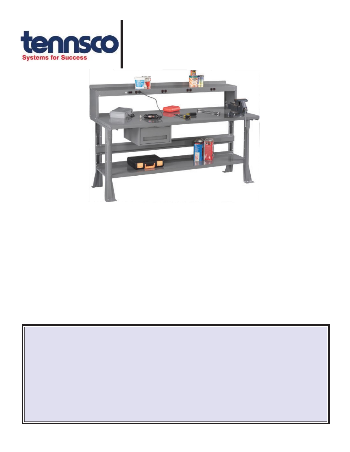
INDUSTRIAL WORKBENCH
With Steel Top
RETAIN INSTRUCTIONS FOR FUTURE REFERENCE!
Congratulations on your purchase of a Tennsco
Workbench! Tennsco's workbenches are ideally
suited for factories, shops, labs, garages, and
more.
Your workbench features a 12-gauge steel top,
formed into a 11/2-inch tall channel formation.
Duplex holes punched into the workbench legs
may be utilized to provide power to your
workbench. The holes are designed to receive
a Steel City electrical box, Model #CDOW (2.5"
x 2" x 3").
Some additional options that are available for
your bench include stackable drawers with an
optional lock, a lower shelf, adjustable legs, side
and back rails, a riser, and an electronic riser.
The parts list on the back of these instruct- ions
provide part numbers for theseaccessories.
PLEASENOTE:Theseinstructionsarefora workbenchwith
flared or adjustable legs. If you have ordered a modular work-
bench (with modular door or drawer units instead of legs)
please disregard these instructions and assemble using the
instructionsthat camewithyourmodular units.
GENERAL SAFETY INFORMATION: Some parts may have sharp edges. CARE must be taken when handling various pieces to
avoid injury. For safety, wear a pair of work gloves when assembling or performing any maintenance on your workbench.
PK-1291010
LIMITED WARRANTY
Tennscowarrantsgoodspurchasedhereundertobefreeofdefectsin materialsand workmanship for aperiod ofone(1)yearfrom thedateofshipment, hereunder.
Thiswarrantyshallnotapplyintheeventgoodsaredamagedasaresult ofmisuse, abuse,neglect, accident, improper application,modification orrepairbypersons
not authorized by Seller, wheregoods are damaged during shipment, or where the date stamps on the goods havebeen defaced, modified or removed. UNLESS
CONSIDEREDUNENFORCEABLEORUNLAWFULUNDERAPPLICABLELAW:
a. ALLIMPLIEDWARRANTIES,INCLUDINGBUTNOTLIMITEDTOWARRANTIESORMERCHANTABILITYANDFITNESSFORAPARTICULARPURPOSE
AREHEREBYEXCLUDED:
b.
BUYERSREMEDY,IFANY,FORANYDEFECTIVEGOODSSHALLBELIMITEDTOAREFUNDBYSELLERORREPLACEMENTOFTHEGOODSAT
SELLER’S OPTION,ANDSHALLINNOEVENTINCLUDEDAMAGESOFANYKIND,WHETHERINCIDENTAL,CONSEQUENTIALOROTHERWISE.
NO GOODS ACCEPTED FOR RETURN WITHOUT PRIOR APPROVAL. Seller shall havethe right toinspect any goods claimed tobedefective at Buyers place
of business or require Buyer to return the goods to Seller for inspection on Seller’s premises. Transportation charges covering returned goods will be borne by
Seller only if such goods are proven tobe defective, are covered by this warranty and are returned within the warranty period stated above.
TENNSCOCorp.,P.O.BOX1888,DICKSON,TN37056-1888
(615)446-8000 or(866)446-8686(tollfree)
Website: www.tennsco.com E-mail: Info@tennsco.com


