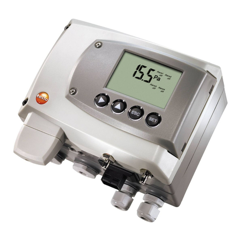
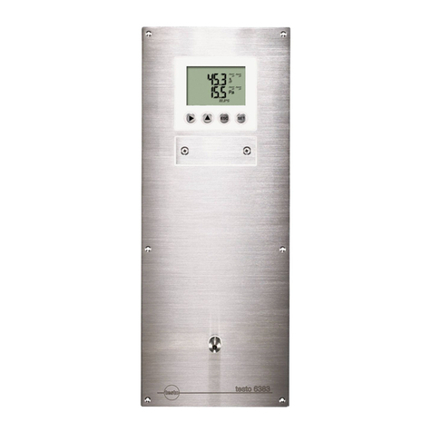
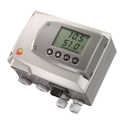
TESTO 6383 User manual

testo 6383 · differential pressure transmitter
P2A software · Parameterizing, adjusting and analyzing
software
Instruction manual

2

1 Safety and the environment
3
1Safety and the environment
Avoiding electrical hazards
> Never use the instrument and connected probes to measure on
or near live parts!
> Damaged mains cables must only be replaced by authorized
personnel.
> Only have the transmitter wired and connected by authorized
personnel with the voltage disconnected.
> You must always comply with the regulations applicable in your
country for opening and repairing electrical equipment.
Avoiding personal injury and damage to equipment
> Installation, setting and calibration work must only be carried
out by qualified and authorized personnel!
> Only open the instrument when this is expressly described in
the instruction manual for installation, maintenance or repair
purposes.
> Observe the permissible storage, transport and operating
temperature.
> Do not store the product together with solvents. Do not use any
desiccants.
> Do not use the instrument for control purposes at the same time
as operating or servicing the transmitter.
> Only operate the product properly, for its intended purpose and
within the parameters specified in the technical data. Do not
use any force.
> Carry out only the maintenance and repair work on this
instrument that is described in the documentation. Follow the
prescribed steps exactly. Use only original spare parts from
Testo.
Any additional work must only be carried out by authorized
personnel. Otherwise testo will not accept any responsibility for the
proper functioning of the instrument after repair and for the validity
of certifications.
Protecting the environment
> At the end of its useful life, send the product to the separate
collection for electric and electronic devices (observe local
regulations) or return the product to Testo for disposal.

2 About this document
4
2About this document
Use
> Please read this documentation through carefully and
familiarize yourself with the product before putting it to use. Pay
particular attention to the safety instructions and warning advice
in order to prevent injuries and damage to the products.
> Keep this document to hand so that you can refer to it when
necessary.
> Hand this documentation on to any subsequent users of the
product.
WARNING Indicates potential serious injuries
CAUTION indicates potential minor injuries
Symbols and writing standards
Representa-
tion
Explanation
Note: Basic or further information.
1. ...
2. ...
Action: more steps, the sequence must be
followed.
> ... Action: a step or an optional step.
- ... Result of an action.
Menu Elements of the program interface.
[OK] Buttons of the program interface.
... | ... Functions/paths within a menu.
“...” Example entries

3 Contents
5
3Contents
1Safety and the environment....................................................................3
2About this document...............................................................................4
3Contents ...................................................................................................5
4Transmitter...............................................................................................8
4.1. Specifications ..................................................................................8
4.1.1. Functions and use ...........................................................................................8
4.1.2. Scope of delivery .............................................................................................8
4.1.3. Accessories .....................................................................................................8
4.1.4. Technical data .................................................................................................8
4.1.5. Dimensions....................................................................................................12
4.2. Product description........................................................................13
4.2.1. At a glance..................................................................................................... 13
4.2.2. Display and keypad........................................................................................14
4.2.3. Service interface ............................................................................................14
4.2.4. Relay board (option) ......................................................................................14
4.2.5. Analog outputs...............................................................................................15
4.2.6. Parameters ....................................................................................................15
4.2.7. Scaling...........................................................................................................15
4.2.8. Alarm handling...............................................................................................16
4.3. Commissioning ..............................................................................17
4.3.1. Mounting preparations ...................................................................................17
4.3.2. Connecting the instrument .............................................................................18
4.3.2.1. Overview of terminals ......................................................................18
4.3.2.2. Connecting voltage supply and analog outputs................................19
4.3.2.3. Connecting the relay outputs ...........................................................20
4.3.2.4. Connecting pressure connections....................................................22
4.3.3. Assembling the instrument.............................................................................23
4.3.4. Ethernet communication ................................................................................24
4.3.4.1. Types of operation...........................................................................24
4.3.4.2. Mains connection.............................................................................24
4.3.4.3. testo as a Saveris component.........................................................24
4.3.4.4. Integration into customer's Ethernet system ....................................25
4.3.5. Adjusting the instrument ................................................................................35
4.3.5.1. Analog output adjustment ................................................................35
4.3.5.2. n-point adjustment ...........................................................................36

3 Contents
6
4.4. Operation ...................................................................................... 37
4.4.1. Relationship between user menu and mini-DIN socket is active .................... 37
4.4.2. Password protection ...................................................................................... 37
4.4.3. Structure of user menu .................................................................................. 37
4.4.4. Overview of the testo 6383 user menu .......................................................... 39
4.4.5. The individual main menus ............................................................................ 41
4.4.5.1. Editing main menu of channel 1 ...................................................... 41
4.4.5.2. Editing Main Menu Alarm ................................................................ 41
4.4.5.3. Editing Main Menu Settings............................................................. 43
4.4.5.4. Editing Main Menu Analysis ............................................................ 45
4.4.5.5. Editing Message main menu ........................................................... 47
4.4.5.6. Calling up Main Menu Ident............................................................. 48
4.4.5.7. Editing Main Menu Adjust................................................................ 48
4.4.5.8. Editing Reset main menu ................................................................ 49
4.5. Status, warning and error messages ............................................ 50
4.5.1. Status messages ........................................................................................... 50
4.5.2. Warning messages ........................................................................................ 51
4.5.3. Transmitter error messages........................................................................... 52
4.5.4. Status code in cyclical service ....................................................................... 53
4.5.5. Handling alarm messages ............................................................................. 53
4.5.6. Namur fault conditions ................................................................................... 54
4.6. Maintenance and cleaning ............................................................ 55
4.6.1. Maintaining the instrument............................................................................. 55
4.6.2. Cleaning the instrument................................................................................. 55
5Parameterizing, adjusting and analyzing software (P2A software) .. 55
5.1. Specifications................................................................................ 55
5.1.1. Functions and use ......................................................................................... 56
5.1.2. System requirements..................................................................................... 56
5.1.3. Scope of delivery ........................................................................................... 57
5.2. First steps ..................................................................................... 57
5.2.1. Installing the software/driver .......................................................................... 57
5.2.1.1. Installing P2A software .................................................................... 57
5.2.1.2. Installing USB driver........................................................................ 57
5.2.1.3. P2A software upgrade..................................................................... 57
5.2.2. Starting the software...................................................................................... 58
5.2.2.1. Starting the program........................................................................ 58
5.2.2.2. Establishing a connection with the instrument ................................. 58
5.2.2.3. Activating the connection with the instrument.................................. 58
3 Contents
7
5.3. Using the software.........................................................................59
5.3.1. User interface ................................................................................................59
5.3.2. Editing instrument/parameter file ...................................................................61
5.3.2.1. Changing instrument/parameter file.................................................61
5.3.2.2. Saving parameters ..........................................................................69
5.3.2.3. Opening the parameter file ..............................................................70
5.3.2.4. Copying and pasting parameters ..................................................... 70
5.3.2.5. Deleting instrument/parameter file ...................................................70
5.3.2.6. Creating a new instrument file .........................................................70
5.3.3. Analyzing/testing the transmitter ....................................................................71
5.3.3.1. Analyzing/testing the instrument......................................................71
5.3.3.2. Carrying out factory reset ................................................................71
5.3.3.3. Testing analog output ......................................................................72
5.3.3.4. Testing switch output relays 1 to 4...................................................73
5.3.3.5. Displaying min./max. values ............................................................74
5.3.4. Adjusting the transmitter ................................................................................75
5.3.4.1. n-point adjustment ...........................................................................76
5.3.4.2. Adjusting the analog output .............................................................77
5.3.5. Transmitter history .........................................................................................78
6Tips and assistance...............................................................................82
6.1. Questions and answers .................................................................82
6.2. Accessories and spare parts .........................................................82
6.2.1. Ordering options for testo 6383 transmitter (0555 6383)................................83

4 Transmitter
8
4Transmitter
4.1. Specifications
4.1.1. Functions and use
The testo 6383 transmitter is suitable for the following applications
with Ethernet networking, amongst others:
• Clean rooms
• Complex room climate applications
In addition to the signal transmission of the readings to a control
unit via analog outputs, the measurement data can simultaneously
be recorded, documented and visualized via Ethernet.
Furthermore, it is possible to issue an alarm for those responsible
for the process, if necessary.
4.1.2. Scope of delivery
The scope of delivery of the testo 6383 transmitter includes the
following:
• Sealing frame
• Instruction manual
• Calibration report
4.1.3. Accessories
The following accessories are available for the testo 6383
transmitter, amongst others:
• Mains unit
• P2A software (parameterizing, adjusting and analyzing
software)
• Assembly accessories
Information about accessories and their order numbers can
be found in Accessories and spare parts or on the
website at www.testo.com.
4.1.4. Technical data
Parameter
• Differential pressure

4 Transmitter
9
Accuracy
The specifications are only valid if the positive pressure is
applied at the positive pressure connection.
• ±0.3 % of measuring range, additional ±0.3 Pa intrinsic error 1
• TK slope drift = 0.02 % of measuring range per degree Kelvin of
deviation from nominal temperature 22 °C
• TK zero point drift= 0 %, as zeroing with solenoid valve2
Measuring range, resolution and overload
Measuring range
depending on
resolution ordered
Resolution Overload
0 to 50 Pa 0.1 Pa 20,000 Pa
0 to 100 Pa 0.1 Pa 20,000 Pa
0 to 500 Pa 0.1 Pa 20,000 Pa
0 to 10 hPa 0.01 hPa 200 hPa
-10 to 10 Pa 0.1 Pa 20,000 Pa
-50 to 50 Pa 0.1 Pa 20,000 Pa
-100 to 100 Pa 0.1 Pa 20,000 Pa
-500 to 500 Pa 0.1 Pa 20,000 Pa
-10 to 10 hPa 0.01 hPa 200 hPa
Upon delivery and following a factory reset the readings are
shown in the display in the unit that was ordered via the
KMAT option Fxx, see Ordering options for testo 6383
transmitter (0555 6383), page 83.
Meas. cycle
• 1/sec
1Measuring uncertainty in accordance with GUM: ±0.5 % of measuring range
final value ±0.3 Pa.
The determination of measurement uncertainty takes place according to GUM (Guide to the Expression
of Uncertainty in Measurement):For the determination of measurement uncertainty, the accuracy of the
measuring instrument (hysteresis, linearity, reproduceability), the uncertainty contribution of the test site
as well as the uncertainty of the adjustment site (works calibration are taken into account. For this
purpose, the value of k=2 of the extension factor, which is usual in measurement technology is used as
a basis, which corresponds to a trust level of 95%.
2Minor mixtures of the media may occur at the positive and negative pressure
side due to the automatic zeroing cycle.

4 Transmitter
10
Interface
• Mini-DIN for P2A software (adjustment and parameterization
software)
• Ethernet interface RJ45 (Ethernet 10 BatesT/100)
Voltage supply
• 4-wire (separate signal and supply lines): 20 to 30 V AC/DC,
300 mA power consumption
Maximum load
• 4-wire: 500 Ω(power output)
Maximal load
• 4-wire: 10 kΩ(voltage output)
Analog output
• 0 to 1 V ± 1.5 mV (4-wire) or
• 0 to 5 V ± 7.5 mV (4-wire) or
• 0 to 10 V ± 15 mV (4-wire) or
• 0 to 20 mA ± 0.03 mA (4-wire) or
• 4 to 20 mA ± 0.03 mA (4-wire)
• TK= 0.05 %K of measuring range per degree Kelvin of
deviation from nominal temperature 22 °C
Resolution of analog output
• 12 bit
Relay
• 4 relays, 250 V AC/DC, 3 A (optional)

4 Transmitter
11
Display
• 2-line LCD with plain text line (optional)
Operating temperature
• -5 to 50 °C/23 to 122 °F
Storage temperature
• -20 to 60 °C/-4 to +140 °F
Process temperature
• -20 to 65 °C/-4 to 149 °F
Housing, weight
• Metal/plastic, approx. 0.9 kg
Protection class, frontal
• IP 65 only if the transmitter is wired, Ethernet connector is
inserted and/or sealing plugs are inserted.
Directives, standards and tests
• EC Directive: 2004/108/EC
• DIN 14644-4
• EN 61000-6-2 interference immunity
• EN 61000-6-3 interference emission
• EN 61326-1+A1+A2
Warranty
• Duration: 2 years
• Warranty conditions: see website www.testo.com/warranty

4 Transmitter
12
4.1.5. Dimensions

4 Transmitter
13
4.2. Product description
4.2.1. At a glance
1Sealing plugs on the positive
pressure test connection
(Ø 4 mm)
2Sealing plugs on the
negative pressure test
connection (Ø 4 mm)
3Socket for service plug
4Display (optional)
5Keys (only with optional
display)
6Test rods for the analog
outputs
7Service cover screw
connection (self-locking,
2 pcs.)
8Aperture for front pressure
connection
9Openings for screws for
fastening to the wall

4 Transmitter
14
10 9-pin connector for the
current/voltage supply
11 Socket for Ethernet interface
12 Relay cover with 12-pin
connector underneath for
relay connection (option)
13 Negative pressure
connection (Ø 6.4 mm)
14 Blind connection as hose
holder for front pressure
connection hose (Ø 6.4 mm)
15 Positive pressure connection
(Ø 6.4 mm)
4.2.2. Display and keypad
The display option allows operation of the testo 6383 transmitter via
the display and four keys.
The LCD display consists of two 7-segment lines for displaying
readings and units and of an information line (for status messages,
for example).
The brightness and contrast of the display and the background
lighting (permanent or off) can be changed via the user menu or the
P2A software.
4.2.3. Service interface
The parameterizing socket (mini-DIN) is located behind the service
cover as an interface to the P2A software.
4.2.4. Relay board (option)
This has a floating switch capacity of 250 V AC/3 A. The switching
limits and hysteresis as well as the function as relay for the
collective alarm can be set via the display or the P2A software.
Further features include:
• Function of changeover contacts (NC/NO contacts) freely
selectable

4 Transmitter
15
• 12 terminals for a total of 4 relays.
If no relays are available, settings for monitoring limit values
or alarms can still be controlled via the display. The alarm
status will be shown on the display.
Only have the transmitter wired and connected by
authorized personnel with the voltage disconnected.
4.2.5. Analog outputs
As analog outputs, the testo 6383 has either
• 1 current output of 0 to 20 mA (4-wire)/4 to 20 mA (4-wire) or
• 1 voltage output of 0 to 1 V/0 to 5 V/0 to 10 V (4-wire)
4.2.6. Parameters
The following parameters are displayed:
• Differential pressure in Pa, hPa, kPa, mbar, bar, mmH2O,
kg/cm2, PSI, inch HG, inch H2O
•
4.2.7. Scaling
There are three types of min./max. values:
1The measuring range: The maximum sensor performance is in
this range. Values outside of the measuring range are displayed
via messages, for example. Measuring range, see table
(below).
2Standard scaling: The output signals are assigned to this
measuring range as standard:
◦during delivery if no entries are made in the order code
◦after exchanging the unit, the measuring range recorded in
the instrument is applied as standard.
The transmitter even retains its scaling with the voltage
disconnected.
Measuring range, see table (below).
3The maximum settings for the manual scaling
◦The maximum limits can be calculated as follows:
X = difference between MIN. and MAX. value of the
standard scaling
(Max. value of standard) + (50 % of X)
(Min. value of standard) - (50 % of X)
◦It is thus possible to scale beyond the measuring range, e.g.
for the adjustment of the scaling limits to standard values of
a PLC.

4 Transmitter
16
With the alarm definition, however, the physical measuring
range limits are decisive.
Measuring
range/standard scaling
Maximum scaling
0 to 50 Pa -5 to 15 Pa
0 to 50 Pa -25 to 75 Pa
0 to 100 Pa -50 to 150 Pa
0 to 500 Pa -250 to 750 Pa
0 to 10 hPa -5 to 15 hPa
-10 to 10 Pa -20 to 20 Pa
-50 to 50 Pa -100 to 100 Pa
-100 to 100 Pa -200 to 200 Pa
-500 to 500 Pa -1000 to 1000
-10 to 10 hPa -20 to 20 hPa
4.2.8. Alarm handling
For upper and lower alarm limits, individual alarms as well as
collective alarms can be specified. If the collective alarm function is
activated, an alarm is triggered as soon as the alarm limit of an
alarm is exceeded, if this alarm is assigned to the collective alarm.
The testo 6383 monitors limit values with the help of relays. If a
reading is outside the limit values, a relay to be specified by the
user is switched.
If the reading reverts to more than a specified hysteresis below or
above the limit value, the alarm is cancelled.
In addition, information about the occurrence of error/status
messages can be provided by means of a collective alarm relay,
see Status, warning and error messages, page 50
If multiple alarm messages are activated at the same time,
the last alarm is shown. If the alarm is cancelled again, the
previous messages are no longer shown.

4 Transmitter
17
4.3. Commissioning
4.3.1. Mounting preparations
1. Create a wall opening (approx. 120 mm x 220 mm) at the
mounting location.
2. Hold 6383 in assembly position and mark the drill holes.
3. Drill holes suitable for the screws to be used.
4. Connect 6383.

4 Transmitter
18
4.3.2. Connecting the instrument
WARNING
Electrical voltage
Danger of injury!
> De-energize the mains connection before connecting the
transmitter.
Only have the transmitter wired and connected by
authorized personnel with the voltage disconnected.
4.3.2.1. Overview of terminals
1Terminal strip for voltage
supply and analog outputs
2Relay terminal strip (option),
below the relay cover
3Relay cover (option)
4Insulating trough for relay
board (option), below the
relay cover
The following description of the terminals refer to this
overview and its numbering.

4 Transmitter
19
4.3.2.2. Connecting voltage supply and analog outputs
Terminal strip for voltage
supply and analog outputs,
item (1) of overview of
terminals
Channels 2 and 3 shown on the pin assignment plan
cannot be used with this instrument.
Wiring diagram for 4-wire system (0 to 20 mA/4 to 20 mA/0 to
1 V/0 to 5 V/0 to 10 V)
11 channel, 0 to
20 mA/4 to
20 mA max.
load per 500 Ω
0 to 1 V/0 to 5 V/
0 to 10 V
2Functional earth
Requirement for the connecting cable of the supply:
• Shielded and insulated with cross-section of at least
0.25 mm², maximum 1.5 mm² without wire end sleeves.
• The supply line must be secured against exceeding
0.5 A.
• An OFF switch must be installed in an easily accessible
position close by and be marked as such.
1. Disconnect terminal strip for voltage supply and analog outputs.
2. Strip the cable ends, clamp wire end ferrules on and screw
down with voltage terminals/channel terminals.

4 Transmitter
20
3. Tie together each of the two adjacent cores using a cable tie.
4. Attach terminal strip for voltage supply and analog outputs.
4.3.2.3. Connecting the relay outputs
Only have the transmitter wired and connected by
authorized personnel with the voltage disconnected.
Relay terminal strip,
item (2) of overview of
terminals
There is the option of twelve terminals for a total of four relays.
1. Remove relay cover.
2. Disconnect relay terminal strip.
3. Strip cable ends and clamp on wire end ferrules.
4. Connect relays according to chosen function (NC/NO) (see
diagrams below; relay 1 is shown as an example of a
connection).
Connection note
• For the connection, a double-insulated mains cable
(sheathed cable) with a cross-section of at least 1.5
mm² must be used.
• Cable connection (2) may not be routed in a loop within
the relay trough (1).
• It is recommended that you always tie 2 adjacent cores
to one another using a cable tie (3).
Other manuals for 6383
4
Table of contents
Other TESTO Transmitter manuals

TESTO
TESTO 6682 Installation instructions

TESTO
TESTO 6682 User manual

TESTO
TESTO 6681 Profibus User manual

TESTO
TESTO 6381 User manual

TESTO
TESTO 6351 User manual

TESTO
TESTO 6381 User manual

TESTO
TESTO 915i User manual

TESTO
TESTO 6681 Profibus User manual

TESTO
TESTO 6740 User manual

TESTO
TESTO 6631 User manual
Popular Transmitter manuals by other brands

PR electronics
PR electronics 4116V106-UK product manual

BWI Eagle
BWI Eagle AIR-EAGLE SR PLUS Product information bulletin

Intelix
Intelix AVOCat AVO-A2-WP-F installation manual

Emerson
Emerson Rosemount 3308 Series Reference manual

Emerson
Emerson Rosemount 702 quick start guide

BWI Eagle
BWI Eagle AIR-EAGLE SR 38-1400-BAT Product information bulletin