TESTO 6740 User manual

Instruction manual en
testo 6740

Preface
2
Preface
Preface
Dear Testo Customer
Congratulations for choosing a Testo product. We hope that you will enjoy many years
of using the product and that it will help you in your work.
If problems should occur which you cannot rectify yourself, please consult our service
department or your dealer. We will endeavour to provide fast and competent assistance
to save you long periods out of operation.

General information 3
General information
This Instruction manual contains important information about the features and use of the
product. Please read this document through carefully and familiarise yourself with the
operation of the product before putting it to use. Keep the Instruction manual to hand so
that you can refer to it when necessary.
Pictograms
This product could be dangerous if operated incorrectly. Information that requires
particular attention is identified in this Instruction manual by pictograms:
Warnings are identified by means of a warning triangle. The relevant signal
word!
indicates the degree of risk:
Warning! means: Serious physical injury could occur if you do not take
the precautionary measures indicated.
Caution! means: Slight physical injury or material damage could occur if
you do not take the precautionary measures indicated.
Pay particular attention to warnings and take the precautionary measures
indicated in order to avoid danger.
Notes on special cases and peculiarities in the handling of the product are indicated
by an exclamation mark.
Standards/Approvals
According to the conformity certificate, this product fulfills all
2004/108/EEC guidelines.
Signal
word!

Contents
4
Contents
Preface ......................................................................2
General information ..................................................3
Contents....................................................................4
1. Basic safety information ............................................5
2. Intended use ............................................................6
3. Product description ..................................................7
3.1 System components ................................................7
3.2 Operating elements ..................................................7
3.3 Settings ..................................................................8
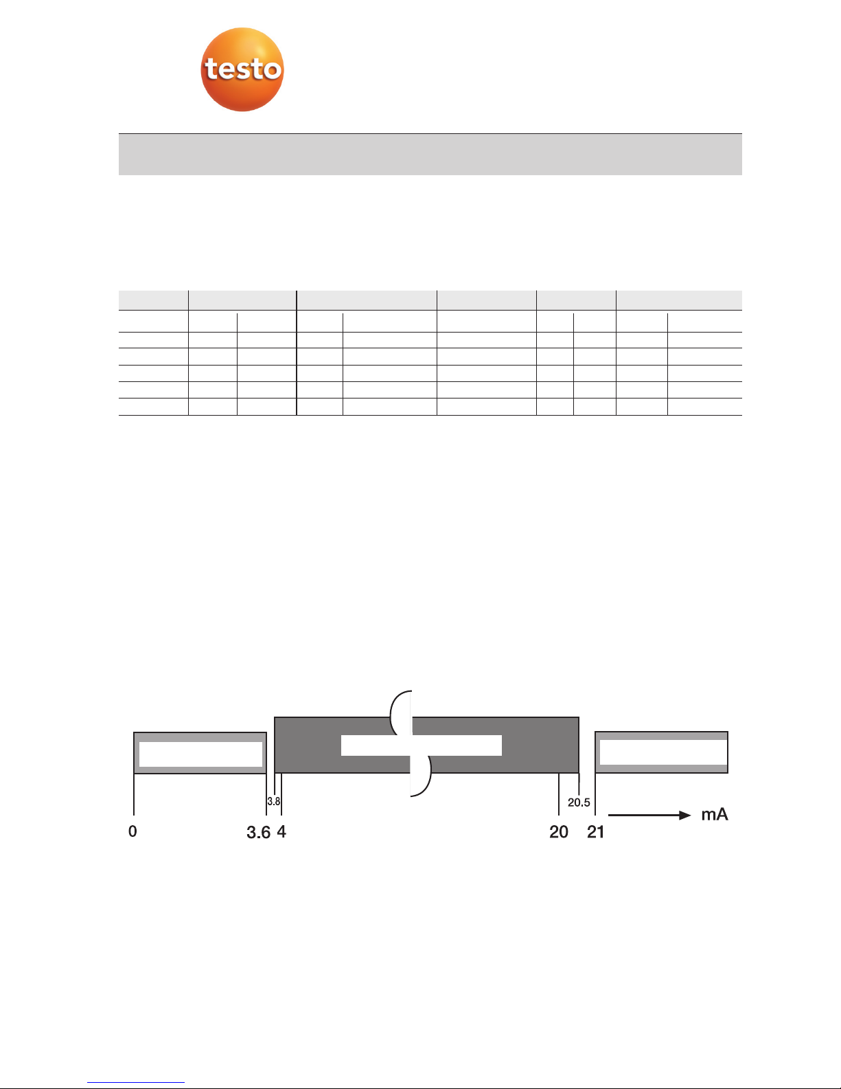
3.4 Current output intervals ............................................8
4. Initial operation ..........................................................9
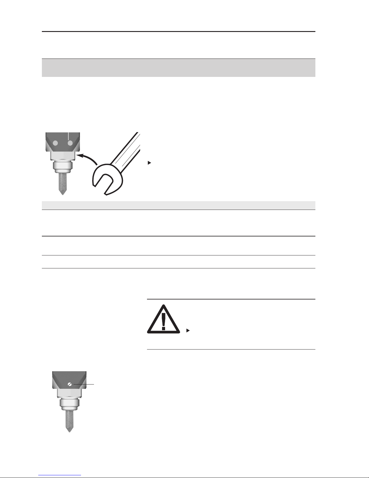
4.1 Mechanical assembly ..............................................9
4.2 Electric connection ..............................................11
4.3 Analog output/Limit signal outputs ........................14
5. Menu guide (0555.6743 /0555.6744 only) ..............16
6. Adjustment on site ..................................................19
7. Care and maintenance ............................................23
8. Troubleshooting ......................................................24
9. Technical data ........................................................25
9.1 Measurement ranges and accuracies ....................25
9.2 Additional instrument data ....................................25
9.3 Uncertainty pressure dewpoint temperature............26
10. Accessories /Spare parts ........................................27

1. Basic safety information 5
1. Basic safety information
Avoid electrical hazards:
Never take measurements with the instrument and its probes on or near live
components unless the instrument is expressly approved for current and voltage
measurements.
Protect the instrument:
Never store the unit together with solvents (e.g. acetone).
Preserving product safety/warranty entitlement:
Operate the instrument only within the parameters specified in the Technical data.
Handle the instrument appropriately and according to its intended purpose.
Never apply force!
Temperature data on sensors/probes refer only to the measurement range of the
sensors. Do not subject handles and lines to temperatures greater than 70°C if they
are not expressly approved for higher temperatures.
Open the instrument for maintenance and repair purposes only if specifically
described in the Instruction Manual.
Maintenance work should only be carried out if described in the Instruction Manual.
Please adhere to the steps described. For safety reasons, please only use spare
parts from Testo.
Any additional work should only be carried out by authorised trained personnel.
Otherwise Testo does not accept responsibility for the functioning of the instrument
following maintenance and for the validity of approvals.
Dispose of carefully:
Once its service life has come to an end, return the instrument to us and we will
dispose of it.

2. Intended use
6
2. Intended use
The instrument is intended for use in the following applications:
The testo 6740 instrument is a pressure dew point transmitter for measuring trace
humidity. It is used in the following areas:
- Monitoring trace humidity in compressed air systems and gas networks
(e.g. pipeline and container drying).
- Controlling and monitoring (compressed air) driers.
- Monitoring compressed air humidity in vehicles.
- Monitoring humidity and temperature in medical compressed air or
granulate driers.
Application in hazardons areas is not allowed!

3. Product description
3.1 System components 7
3. Product description
3.1 System components
To
process
Cooling
coil 1
0554.3304
Measurement
chamber 22
0554.3303
G½, without display
0555.6741
NPT½“, without display
0555.6742
G½, with display
0555.6743
NPT½“, with display
0555.6744
Standard plug, 4 to 20mA
(included with all instruments)
Accessories:
0554.3302 plug (4 to 20mA,
2 switch contacts, 2 LEDs)
1Only required for process
temperatures > 50°C, cooling coil
only in connection with measurement
chamber
2Measurement chamber only required
if
- incoming flow is to be increased
(measurement chamber guarantees
a minimum incoming flow of 1l/min
at a positive pressure of 6bar).
- fast assembly/dismantling of
transmitter without interrupting
process is required.
To
PLC/control/
analysis unit
3.2 Operating elements
The instruments with the article numbers 0555.6741
and 0555.6742 do not have any additional operating
elements.
The instruments with the article numbers 0555.6743
and 0555.6744 have a keypad and a display to input
and read off settings (See 5. Menu guide, p. 16).
All of the instruments of Type testo 6740 can be
parameterised with the aid of the 0554.3305 scaling
adapter.
Standard quick-release device
G½ thread
Max. pressure: 15barabs
Max. pressure: 50barabs

3.3 Settings
The parameters in the instrument are assigned the
following values in the factory (default values):
3. Product description
3.3 Settings
8
Parameter Pressure dew point 1Atmospheric dew point 1Relative humidity Temperature Absolute humidity
Unit °Ctp °Ftp °CtA °FtA %rF, %rh, %Hr °C °F ppmvmg/m3(Abs)
4mA -60 -75 -60 -75 003200
20mA 30 85 30 85 100 50 120 30000 230000 2
LS 4 40 4 40 30 10 50 8400 7000
US 10 55 10 55 50 30 85 13000 9600
Hyst 2 2 2 2 2 2 2 2 2
1With dew point temperatures <0°Ctp / <0°CtA/ <32°Ftp /<32°FtA the frostpoint temperature (dewpoint upon ice)
is displayed
2Display is shown to the power of ten: 30E3 (corresponds to 30 x 103= 30 x 1000 = 30000)
3.4 Current output intervals
Failure information A Measurement information M Failure information A

4. Initial operation
4.1 Mechanical assembly 9
4.1 Mechanical assembly
We recommend you wrap the thread of the process
connection in sealing tape (e.g. PTFE) or place it in a
copper gasket (inner diameter: 21mm).
Force should only be applied to the Allen screw .
There are 3 different options for assembly depending
on the application:
Without measurement chamber and cooling coil
Compressed air!
Risk of injury!
Depressurise pipe sections (e.g. compressor
off or use bypass) and aerate before opening.
1Screw process connection (G½ or NPT½“) into the
matching thread.
The housing can be rotated by 350°. Do not use force
when aligning.
2Set up housing so that the display can be easily
read. Tighten grub screw .
3Complete aeration of pipe section and apply
pressure to pipe section.
4. Initial operation
Assembly Application
Without measurement chamber - Process temperatures 0 to 50°C
and cooling coil - It is possible to attach sensor directly in process
- No quick assembly/dismantling of testo 6740 required and
flow on sensor is sufficient (1l/min)
With measurement chamber - Process temperatures 0 to 50°C
- Fast assembly/dismantling of testo 6740 required and/or
flow on sensor is insufficient (1l/min)
With measurement chamber - Process temperatures 50 to 200°C
and cooling coil
Warning

4. Initial operation
4.1 Mechanical assembly
10
With measurement chamber (max. 15bar)
1Connect measurement chamber without measure-
ment transmitter to the compressed air push-in
quick connection for approx. 10 - 30 s, in order to
blow out any dirt deposits
2Remove measurement chamber from compressed
air push-in quick connection.
3Screw in process connection (G½) of the
testo 6741/6743 transmitter in measurement
chamber thread.
4Snap push-in quick connection of measurement
chamber in standard socket of compressed air line.
With measurement chamber and cooling coil
(max. 15bar)
1Connect measurement chamber without measure-
ment transmitter to the compressed air push-in
quick connection for approx. 10 - 30 s, in order to
blow out any dirt deposits
2Remove measurement chamber from compressed
air push-in quick connection.
3Screw in process connection (G½) of testo 6741/
6743 transmitter into thread of measurement
chamber.
4Snap push-in quick connection of measurement
chamber in push-in quick connection of the cooling
coil.
5Snap second push-in quick connection of the
cooling coil into the standard socket of the
compressed air line.

4. Initial operation
4.2 Electric connection 11
1
3
2
lliifftt
4.2 Electric connection
Standard plug
We recommend an 8 wire cable with a tightly braided
screen and a core cross-section of 0.2 to 0.5mm2.
1Loosen and remove screw at the back of the
plug and remove plug from transmitter .
2Remove plug socket from the plug housing. To do
this apply a small screwdriver to the point marked
with “lift“ and press out carefully .
3Screw on the cable positioning device and guide
the cables through the plug housing .
4Connect cable ends to the screw terminals of the
plug socket :
Plug socket terminals
1: + (4 to 20mA), power: 12...30VDC
2: - (4 to 20mA)
3: Not assigned
4: Measuring earth (cable screen)
5Insert plug socket into plug housing again until it
snaps into place and screw on cable fixing unit.
6Attach plug to transmitter and secure with screw
.

4. Initial operation
4.2 Electric connection
12
1 2 3 4 5 6
I+
Flexible lead of relay board
Screen
on PE
I-
1
3
2
Plug socket terminals
1: I+ (4 to 20mA)
2: I- (4 to 20mA)
3: (connected to relay
board in factory)
: Put on screen
Relay board terminals
1: 20 to 28VDC
2: LS+
3: LS-
4: US+
5: US-
6: 0VDC
Current
signal and
supply 20 to
28VDC
Plug
socket
Relay board
The supply lines need
to be galvanically
connected, so connect
either - or - !
0554.3302 plug (with 2 switch outputs)
We recommend an 8 wire cable with a tightly braided
screen, wire cross-section 0.2 to 0.8mm2.
1Loosen and remove screw at the back of the
plug and remove plug from transmitter .
2Tilt the cover of the plug housing at an angle and
remove .
3Remove plug socket from the front and the relay
board from the back out of the plug housing.
4Screw on cable positioning device and guide
cables through the plug housing.
5Connect cable ends to the screw terminals of the
relay board or the plug socket :

4. Initial operation
4.2 Electric connection 13
6Push plug socket and plug board into the plug
housing (pay attention to alignment) and close lid.
7Screw on cable positioning device.
8Attach plug to transmitter and screw into place
.

4. Initial operation
4.3 Analog output/Limit signal outputs
14
4.3 Analog output/
Limit signal outputs
Standard plug/0554.3302 plug
Both plug variations have a 4 to 20mA analog output
available in two-wire technology.
RL
x
yPPoowweerr
Standard plug:
U = 12 to 30VDC
0554.3302 plug:
U = 20 to 28VDC
xx,,yy
ccoonnnneeccttiioonn::
Connection
x Terminal 1
y Terminal 2
MMaaxx..
llooaadd
RRL
((eexxtteerrnnaall
llooaadd))::
U Standard 0554.3302
12V 50 Ohm -
24V 650 Ohm 650 Ohm
30V 950 Ohm - 4 to 20mA

4. Initial operation
4.3 Analog output/Limit signal outputs 15
Limit signal outputs with 0554.3302 plug
Two floating contacts (NO contact) are available.
LS
LS= On
LS= Off
US= On
US= Off
Switch contact closed
Switch contact open
RReessttffeeuucchhttee
((zz..BB..
aallss
DDrruucckkttaauuppuunnkktt,,
°°CCttppdd))
Definition Lower
Switch (LS),
default setting:
4°Ctpd
Definition Upper
Switch (US),
default setting:
10°Ctpd
HHYYSStt, default
setting: 2K HHYYSStt
}
}
Terminal 2
Terminal 3
US
Terminal 4
Terminal 5
MMaaxx..
cciirrccuuiitt::
30VDC / 0.5A
Switching point
LS + HYST,
default setting:
6°Ctpd
Switching point
US + HYST,
default setting:
12°Ctpd
Default settings for other parameters (ppm, %RH, ...)
See 3.3 Settings, p.8
Example:
- The lower alarm shall be switched at +8 °Ctpd
- The higher alarm shall be switched at +12 °Ctpd
Set these values
- LS = 6 °Ctpd
- US = 10 °Ctpd
- Hyst = 2 °C
- Switching point lower alarm = LS + Hyst = 8 °Ctpd
- Switching point upper alarm = US + Hyst = 12 °Ctpd

16 5. Menu guide
5. Menu guide (0555.6743/0555.6744 only)
Set unit (Unit)
Pressure dew point °Ctp/
°Ftp, atm. dew point 5°CtA/
°FtA, rel. humidity %rF/%Hr/
%rh, absolute humidity
mg/m3(display: abs) 5/ppmv,
temperature °C, °F
Select with
Set 4mA value
(S-Lo) 2
Define lower limit of scale
6
= +1
= Next digit
Set 20mA (S-Hi) 2
Define upper limit of scale 6
= +1
= Next digit
Set delay menu query
(Pti)
1s / 3s / 5s / 10s
Select using
De/Activate (dS-1) “display
can be switched off”
ON = Display can be
switched off
OFF = Display cannot be
switched off
Select using
De/Activate (dS-
2)“Change value/unit”
ON = 6s value, 2s unit
OFF = Value continuously
Select using
Set absolute pressure in
bar (PrES)5
= +1
= Next digit
Test analog output (AtES)
-- = No signal
4 = 4mA
12 = 12mA
20 = 20mA
Select using
Activate using
ProG
Display: Min. value (Lo)
Display: Max. value (Hi)
Set code (UCod) 7
= +1
= Next digit
Display mode 1,2,11, 13
Reading and unit alternately / Reading continuously (see)
Unit
Return to Unit
Return to ProG
3
Display from (see)
CodE
Enter code 10
4 digit password, default
setting: 6810
= +1
= next digit
4
Signs and symbols:
Press button briefly.
Keep button pressed for 2s.
Change menu using button specified.
Save input using and change menu
or change menu using without
saving input.

17
5. Menu guide
Set lower switching
point (LS) 6
= +1
= Next digit
Set upper switching
point (US) 6
= +1
= Next digit
Set hysteresis value
(HYSt)
= +1
= Next digit
Test limit signal outputs
(tESt)
-0- = Both operating
points off
-1- = Lower operating
point on
-2- = Upper operating
point on
Select with
Activate with
Reference value > -60°tpd
(rEF) 9
= +1
= Next digit
Carry out reset (rES)
nor = No reset
rS = Reset (return to
default setting))
Select using
Notes:
1If there are breaks in the input, the system returns automatically to
the display mode after approx. 1min.
2In the case of the units ppm and Abs (mg/m3), values are
displayed/entered to the power of ten. Examples:
15E1 corresponds to 15 x 10 = 150, 02E2 corresponds to
2 x 100 = 200, 21E3 corresponds to 21 x 1000 = 21000
3Keep button pressed (1s/3s /5s/10s, corresponding to setting
in , default setting: 5s).
4Only with deactivated code (can be set in PPrroogg- UUCCooddmenu).
5Absolute pressure (can be set in PPrroogg- PPrreessmenu) is included in
the calculation of the ppm value and atmospheric dew point (°CtA/
°FtA).
6For negative values: select “-“ at left digit position.
7To deactivate codes: Enter 0000. Important: Note down the code
at a suitable point, operation is impossible without a valid code.
8Can only be used together with the 0554.3302 plug.
9Menu is only available if one of the following units is set: °Ctp, °Ftp,
%rF, %Hr or %rh (can be set in UUnniittmenu). Also see 6. Adjustment
on site, p. 18.
10 General password (always valid): 6810
11 The displayed reading flashes if the scaling limits are exceeded
(can be set in Menu UUNNIITT- SS-LLooor SS-HHii).
12 Compare chapter 6.
13 Display blinks if actual values are below 4mA setting or above
20mA setting.
ALAr 8AdJ12 rST
Return to ALAr
Return to AdJ
Return to rSt
Return to UNIT

5. Menu guide
18
( 0555.6743 only) supplement
available from versioin June 2007 on. For older versions an update
of the firmware is necessary
Reference value > -60°tpd
(rEF) 9
= +1
= Next digit
Carry out reset (rES)
nor = No reset
rS = Reset (return to
default setting))
Auswahl mit
Comments:
14 Can only be used in combination with a 2-point adjustment (cf.
chap 6.2)
15 In this setting point, P1 and the relative humidity at the pressure
level P1 are alternately displayed.
Please wait until the relative humidity has a constant value, and
only then press the SET button.
16 In this setting point, P2 and the relative humidity at the pressure
level P2 are alternately displayed.
Switch the switchover cock of the adjustment device and then wait
until the relative humidity has a constant value, and only then press
the SET button.
AdJ rST
Return to AdJ Return to rSt
Set pressure ratio
Pr= P1/P2
= +1
= Next digit
2PA 14
Return to 2PA
Return to UNIT
Display value P115
Display value P216

6. Adjustment on site 19
6. Adjustment on site
One point adjustment by inputting one reference
value
Using one point adjustment, you can enter a reference
value for a working point (e.g. -40°C tpd) specified by
you. In this way you will achieve a minimum
target/actual deviation from this working point.
A dew point mirror is ideal as a reference measuring
instrument.
The Adj menu in which the reference value is
entered is only available if one of the following units
is set: °Ctp, °Ftp, %rF, %Hr or %rh (See 5. Menu
guide, p. 16, Unit menu, Setting unit).
Reference value input
Optimum precision is achieved at reference value
-40 °C tpd. In case low dewpoints (<-25 °C tpd) are
relevant, it is suggested to avoid reference values
>-30 °C tpd (else loss of precision).
1Expose reference measuring instrument and
testo 6740 to identical, constant conditions and
await adjustment time.
2Measure reference value and compare with
testo 6740 reading.
3If there are deviations in the values, enter reference
value in Adj menu.

6. Adjustment on site
20
Two-point adjustment for testo 6743
available from versioin June 2007 on. For older
versions an update of the firmware is necessary
(please adress Testo service)
2-pressure adjustment device (0554 3314)
Adjustment chamber
Switchover cock
Sintered filter
A two-point adjustment can be carried out with the
testo 6743 and the 2-pressure adjustment device ().
The two-point adjustment serves to adjust the
testo 6743 to trace humidity. A reference instrument
or humidity generator is not necessary. Depending on
the position of the switchover cock () of the
2-pressure adjustment device (), the sensor of the
testo 6743 is exposed to two different pressure levels.
In front of the switchover cock () of the
2-pressure adjustment device () is a sintered filter
() which prevents dirt particles, rust and oil from
entering the adjustment chamber ().
The 2-pressure adjustment device () must be
under an absolute pressure of min. 3 bar and
max. 16 bar.
The calibration certificate of the 2-pressure
adjustment device is obligatorily required for the
pressure relationship P1/P2.
Other manuals for 6740
1
Table of contents
Other TESTO Transmitter manuals