Toro Multi Pro 41240 User manual

FormNo.3447-819RevA
Note:TheinstallationoftheMultiProWMrequirestheinstallation
of1ormoreinterdependentkits.Contactyourauthorized
Torodistributorformoreinformation.
MultiPro®WMTurfSprayer
ModelNo.41240—SerialNo.409500000andUp
Registeratwww.Toro.com.
OriginalInstructions(EN)*3447-819*

ThisproductcomplieswithallrelevantEuropean
directives;fordetails,pleaseseetheseparateproduct
specicDeclarationofConformity(DOC)sheet.
ItisaviolationofCaliforniaPublicResourceCode
Section4442or4443touseoroperatetheengineon
anyforest-covered,brush-covered,orgrass-covered
landunlesstheengineisequippedwithaspark
arrester,asdenedinSection4442,maintainedin
effectiveworkingorderortheengineisconstructed,
equipped,andmaintainedforthepreventionofre.
WARNING
CALIFORNIA
Proposition65Warning
Useofthisproductmaycauseexposure
tochemicalsknowntotheStateof
Californiatocausecancer,birthdefects,
orotherreproductiveharm.
Introduction
Whenproperlyinstalled,thisattachmentconverts
avehicleintoadedicatedturfsprayapplication
machine,anditisintendedtobeusedbyprofessional,
hiredoperatorsincommercialapplications.Itis
designedprimarilyforsprayingonwell-maintained
lawnsinparks,golfcourses,sportselds,andon
commercialgrounds.
Readthisinformationcarefullytolearnhowtooperate
andmaintainyourproductproperlyandtoavoid
injuryandproductdamage.Youareresponsiblefor
operatingtheproductproperlyandsafely.
Visitwww.T oro.comformoreinformation,including
safetytips,trainingmaterials,accessoryinformation,
helpndingadealer,ortoregisteryourproduct.
Wheneveryouneedservice,genuineT oroparts,or
additionalinformation,contactanAuthorizedService
DealerorToroCustomerServiceandhavethemodel
andserialnumbersofyourproductready.Figure1
identiesthelocationofthemodelandserialnumbers
ontheproduct.Writethenumbersinthespace
provided.
Important:Important:Withyourmobiledevice,
youcanscantheQRcodeontheserialnumber
decal(ifequipped)toaccesswarranty,parts,and
otherproductinformation.
g238191
Figure1
1.Locationofthemodelandserialnumbers
ModelNo.
SerialNo.
Thismanualidentiespotentialhazardsandhas
safetymessagesidentiedbythesafety-alertsymbol
(Figure2),whichsignalsahazardthatmaycause
seriousinjuryordeathifyoudonotfollowthe
recommendedprecautions.
g000502
Figure2
1.Safety-alertsymbol
Thismanualuses2wordstohighlightinformation.
Importantcallsattentiontospecialmechanical
informationandNoteemphasizesgeneralinformation
worthyofspecialattention.
©2021—TheToro®Company
8111LyndaleAvenueSouth
Bloomington,MN554202
Contactusatwww.Toro.com.
PrintedintheUSA
AllRightsReserved

Contents
Safety.......................................................................4
GeneralSafety...................................................4
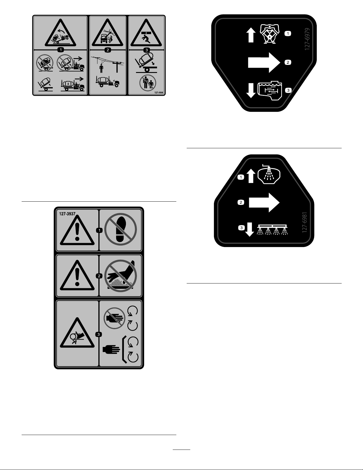
SafetyandInstructionalDecals..........................5
Setup........................................................................9
1RemovingtheExistingBed.............................11
2PreparingtoInstalltheT ankSkid...................12
3InstallingtheHold-DownBracketsforthe
TankSkid......................................................13
4InstallingtheTankSkid..................................13
5AssemblingtheDrainValve...........................15
6DisconnectingtheBattery..............................16
7ConnectingtheSpeedSensor
Harness........................................................17
8CouplingtheSprayerPump...........................18
9InstallingtheControlConsoletothe
Machine........................................................18
10InstallingtheElectricalHarnessesforthe
Sprayer.........................................................19
11InstallingtheSprayerFuseBlock.................20
12ConnectingtheSprayerHarnesstothe
Battery..........................................................22
13LoweringtheTankSkid................................25
14InstallingtheCenterBoomSection...............26
15InstallingtheLeftandRightBoom
Section..........................................................27
16InstallingtheBoomHoses............................29
17InstallingtheNozzles...................................31
18InstallingtheFreshwaterT ank......................31
19InstallingtheAnti-SiphonFill
Receptacle....................................................33
20StoringtheJackStands(Optional)...............34
ProductOverview...................................................35
Controls...........................................................35
Specications..................................................38
Attachments/Accessories.................................38
BeforeOperation.................................................38
BeforeOperationSafety...................................38
UsingtheInfoCenter.........................................39
PerformingPre-StartingChecks.......................49
PreparingtheSprayer.......................................49
CalibratingtheSprayer.....................................53
CalibratingtheSprayerSpeed..........................54
CalibratingtheSection-BypassValves..............55
AdjustingtheAgitationandMasterBypass
Valves...........................................................56
LocatingtheSprayPump..................................57
DuringOperation.................................................57
DuringOperationSafety...................................57
OperatingtheSprayer......................................59
Spraying...........................................................59
TurfCarePrecautionswhileOperatingin
StationaryModes..........................................60
PositioningtheSpraySections.........................60
SprayingTips....................................................61
UncloggingaNozzle.........................................62
AfterOperation....................................................62
AfterOperationSafety......................................62
CleaningtheSprayerSystem...........................62
CleaningtheSuctionFilter................................63
CleaningthePressureFilter.............................64
CleaningtheNozzleFilter.................................65
ConditioningtheSpraySystem.........................65
TransportingorT owingtheMachine.................66
Maintenance...........................................................67
MaintenanceSafety..........................................67
RecommendedMaintenanceSchedule(s)...........68
DailyMaintenanceChecklist.............................69
NotationforAreasofConcern...........................69
Pre-MaintenanceProcedures..............................70
AccessingtheMachine.....................................70
Lubrication..........................................................71
GreasingtheSprayerPump.............................71
GreasingtheBoomHinges...............................72
ElectricalSystemMaintenance...........................72
ElectricalSystemSafety...................................72
ReplacingtheFuses.........................................72
SpraySystemMaintenance.................................73
InspectingtheHoses........................................73
ChangingtheSuctionFilter...............................73
ChangingthePressureFilter............................73
ChangingtheNozzleFilter................................74
InspectingtheSprayerPump............................75
InspectingtheNylonPivotBushings.................75
AdjustingtheBoomstoLevel............................76
Cleaning..............................................................77
CleaningtheFlowmeter...................................77
CleaningtheSprayerValves.............................77
Storage...................................................................88
StorageSafety..................................................88
PreparingtheMachineforStorage...................88
Long-TermStorage...........................................89
PreparingtheMachineforService....................90
RemovingtheSprayerandT ankSkid...............90
Troubleshooting......................................................93
Schematics.............................................................94
3

Safety
Improperuseormaintenancebytheoperatororowner
canresultininjury.T oreducethepotentialforinjury,
complywiththesesafetyinstructionsandalwayspay
attentiontothesafety-alertsymbol(Figure2),which
meansCaution,Warning,orDanger—personalsafety
instruction.Failuretocomplywiththeinstructionmay
resultinpersonalinjuryordeath.
Thismachinehasbeendesignedinaccordancewith
therequirementsofSAEJ2258.
GeneralSafety
Thisproductiscapableofcausingpersonalinjury.
Alwaysfollowallsafetyinstructionstoavoidserious
personalinjury.
•Readandunderstandthecontentsofthis
Operator’sManualbeforestartingtheengine.
•Useyourfullattentionwhileoperatingthe
machine.Donotengageinanyactivitythat
causesdistractions;otherwise,injuryorproperty
damagemayoccur.
•Useappropriatepersonalprotectiveequipment
(PPE)toguardagainstcontactwithchemicals.
Chemicalsubstancesusedinthesprayersystem
maybehazardousandtoxic.
•Donotputyourhandsorfeetnearmoving
componentsofthemachine.
•Donotoperatethemachinewithoutallguards
andothersafetyprotectivedevicesinplaceand
workingonthemachine.
•Keepclearofanydischargeareaofthesprayer
nozzlesandspraydrift.Keepbystandersand
childrenoutoftheoperatingarea.
•Neverallowchildrentooperatethemachine.
•Parkthemachineonalevelsurface,engagethe
parkingbrake,shutofftheengine,removethekey
(ifequipped),andwaitforallmovementtostop
beforeyouleavetheoperator’sposition.Allow
themachinetocoolbeforeadjusting,servicing,
cleaning,orstoringit.
Improperlyusingormaintainingthismachinecan
resultininjury.T oreducethepotentialforinjury,
complywiththesesafetyinstructionsandalways
payattentiontothesafety-alertsymbol,which
meansCaution,Warning,orDanger—personalsafety
instruction.Failuretocomplywiththeseinstructions
mayresultinpersonalinjuryordeath.
Notalltheattachmentsthatadapttothismachine
arecoveredinthismanual.Refertotheoperator’s
manualprovidedwitheachattachmentforadditional
safetyinstructions.
4

SafetyandInstructionalDecals
Safetydecalsandinstructionsareeasilyvisibletotheoperatorandarelocatednearanyarea
ofpotentialdanger.Replaceanydecalthatisdamagedormissing.
decal131-5808
131-5808
1.Automatic—closed
loop-ratecontrol
2.Manual—openloop-rate
control
decal120-0616
120–0616
1.Warning—readtheOperator’sManual;usefresh,clean
waterforrst-aidwashing.
decal120-0622
120–0622
1.Warning—readthe
Operator’sManual.
3.Chemicalburnhazard;
toxicgasinhalation
hazard—wearhandand
skinprotection;weareye
andrespiratoryprotection.
2.Warning—donotenterthe
sprayertank.
decal119-9434
119-9434
1.Tankcontents
decal104-8904
104-8904
1.Grasptheboomhere.
5

decal127-6976
127-6976
1.Decrease2.Increase
decal120-0617
120–0617
1.Severinghazardofhand,
pinchingpoint—keep
awayfromactuatedjoints.
2.Crushinghazard—keep
bystandersawayfromthe
machine.
decal125-4052
125–4052
1.Raiseleftboom4.Lowerrightboom
2.Lowerleftboom5.Toggletankrinseon/off
3.Raiserightboom6.Togglesonicboomon/off
decal125-8139
125–8139
1.Toggleboomsprayerson/off
decal127-3966
127–3966
1.ReadtheOperator’s
Manualforinformationon
fuses.
4.7.5A—TECcontroller
output
2.30A—T ankrinse5.10A—Ignition
3.2A—TECcontrollerlogic6.15A—Sprayerboom
6

decal127-3936
127–3936
1.Backwardtipping
hazard—donotraise
afulltank;donotmove
themachinewitharaised
tank;onlyraiseand
emptytank;onlymovethe
machinewithalowered
tank.
3.Crushinghazard—keep
bystandersawaywhen
loweringthetank.
2.Electricalshockhazard,
overheadpower
lines—checkthearea
foroverheadpowerlines
beforeoperatingthe
machineinthearea.
decal127-3937
127–3937
1.Warning—donotstep.3.Entanglementhazard,
belt—keepawayfrom
movingparts;keepall
guardsandshieldsin
place.
2.Warning—keepawayfrom
hotsurfaces.
decal127-6979
127-6979
1.Bypass-returnow3.Agitationow
2.Flow
decal127-6981
127-6981
1.Bypass-returnow3.Boomspray
2.Flow
7

decal127-6982
127-6982
1.Bypass-returnow2.Boomspraydecal127-6984
127-6984
1.Flow2.Tank-returnow
decal130-8294
130-8294
1.Leftboom5.Centerboomsprayon9.Rightboomsprayoff13.Agitation
2.Leftboomsprayon6.Centerboomsprayoff10.Speed14.Agitationon
3.Leftboomsprayoff7.Rightboom11.Increasespeed15.Agitationoff
4.Centerboom8.Rightboomsprayon12.Decreasespeed
8

Setup
LooseParts
Usethechartbelowtoverifythatallpartshavebeenshipped.
ProcedureDescriptionQty.Use
1Nopartsrequired–Removetheexistingbed.
RearPTOKit,Heavy-DutyWorkman
Vehicle(HD-SeriesModelswitha
ManualTransmission)
1
High-FlowHydraulicsKit,
WorkmanHDX-AutoUtilityVehicle
(Non-TC—HDX-AutoModel)
1
MultiProWMTurfSprayerFinishing
Kit,ManualWorkmanUtilityVehicle
(HD-SeriesModelswithaManual
Transmission)
1
2
MultiProWMTurfSprayerFinishing
Kit,AutomaticWorkmanUtilityVehicle
(HDX-AutoModel)
1
Preparetoinstallthecenterboom
section.
3Hold-downbrackets2Installtheattachmenthold-down
brackets.
Tankandskidassembly1
Clevispins2
Taperedclevispin2
Hairpins2
Lynchpins4
Bolt(1/2x1-1/2inches)2
4
Nuts(1/2inch)2
Installthetankskid.
5Nopartsrequired–Assemblethedrainvalve.
6Nopartsrequired–Disconnectthebattery.
7Nopartsrequired–Connectthespeedsensorharness.
8Nopartsrequired–Couplethesprayerpump.
Consolemountingbracket1
Flangelocknut(5/16inch)3
Flange-headbolt(5/16inch)3
Plasticbushing2
Controlconsole1
Spring-clippin1
9
Handknob1
Installthecontrolconsoletothe
machine.
J-clips3
Bolt(1/4x3/4inch)1
10Flangenut(1/4inch)1
Installthecontrolconsoleontothe
machine.
11Fusedecal(127–3966)1Installthecontrolconsoleandthe
electricalharness.
9

ProcedureDescriptionQty.Use
Batteryterminalbolt2
Clampnut2
12Cover—wide(batteryterminal—red)1
Connectthesprayerharnesstothe
battery.
Bolt(1/2x1-1/2inch)2
13Locknut(1/2inch)2Lowerthetankskid.
Center-boomassembly1
Bolt(3/8x1inch)10
Flangelocknut(3/8inch)10
Boom-transportcradle2
Bolt(1/2x1-1/4inches)4
14
Flangenut(1/2inch)4
Installtheboomsection.
Leftboomsection1
Rightboomsection1
Flange-headbolts(3/8x1-1/4inches)8
Backingplates8
Flangelocknuts(3/8inch)8
Clevispin2
15
Hairpin2
Installtheleftandrightboomsections.
Hoseclamps3
R-clamp2
Shoulderbolt2
Washer2
16
Nut2
Installtheboomhoses.
Freshwatertank1
90°elbow(3/4inchNPT)1
90°spigot1
Freshwater-tankmount1
Mountstrap4
Flange-headbolt(5/16x5/8inch)4
Flangelocknut(5/16inch)10
Supporttube(freshwatertank)1
Jamnut(5/16inch)1
Bolt(5/16x1inch)1
Shoulderbolt(1/2x1-15/16inches)2
Bolt(5/16x2-1/4inches)2
18
Washer(5/16inch)2
Installthefreshwatertank.
Fillreceptacleassembly1
19Flange-headbolt(5/16x3/4inch)1Installtheanti-siphonllreceptacle.
Frontjackstand2
Rearjackstand2
Cotterpin4
Clevispin(4-1/2inches)2
Clevispin(3inches)2
20
Knob2
Storethejackstands(optional).
10

MediaandAdditionalParts
DescriptionQty.Use
Operator'sManual1
PartsCatalogInstructionCard1
Screenlter2
Readthemanualsbeforeoperatingthemachine.
Note:Determinetheleftandrightsidesofthemachinefromthenormaloperatingposition.
Note:Ifyouhavequestionsorneedadditionalinformationregardingthespraycontrolsystem,refertothe
Operator’sManualsuppliedwiththesystem.
Important:Thissprayerissoldwithoutspraynozzles.
Tousethesprayer,youmustobtainandinstallthenozzles.ContactyourauthorizedTorodistributorfor
informationontheavailablesectionkitandaccessories.
Afteryouinstallyournozzlesandbeforeusingthesprayerforthersttime,adjustthesectionbypass
valvessothatthepressureandapplicationrateremainsthesameforallsectionswhenyouturn1or
moresectionsoff.RefertoCalibratingtheSprayerFlow(page53).
Important:TheMulti-ProWMturfsprayerrequiresa4-postROPSorcabinstalledwiththeWorkman
vehicle.
1
RemovingtheExistingBed
NoPartsRequired
Procedure
CAUTION
Thefullbedweighsapproximately95kg(210
lb).Youcaninjureyourselfifyouremovethe
bedwithoutaid.
•Donottrytoinstallorremovethebedby
yourself.
•Getthehelpof2or3otherpeopleoruse
anoverheadcrane.
1.Parkthemachineonalevelsurface,engagethe
parkingbrake,andstarttheengine.
2.Movethehydraulicliftleverforwardandlower
thebeduntiltheclevispinsforthecylinderrod
endliftcylindersarelooseinthemountingslots
ofthebedmountingplates.
3.Releasethehydraulicliftlever,setthehydraulic
liftlocklever,shutofftheengine,andremove
thekey;refertotheOperator’sManualofyour
machine.
4.Removethelynchpinsfromtheouterendsof
thecylinderrodclevispins(Figure3).
g002368
Figure3
1.Cylinderrodend4.Lynchpin
2.Bedmountingplate5.Rearslots(fullbed)
3.Clevispin6.Frontslots(2/3bed)
5.Removetheclevispinssecuringthecylinder
rodendstothebedmountingplatesbypushing
thepinstowardthecenterlineofthemachine
(Figure3).
6.Removethelynchpinsandclevispinssecuring
thepivotbracketsofthebedtotheframe
channelsofthemachine(Figure4).
11

g002369
Figure4
1.Left,rearcornerofbed4.Clevispin
2.Vehicleframechannel5.Lynchpin
3.Pivotplate
7.Liftthebedoffthevehicle.
8.Stowtheliftcylindersinstorageclips.
2
PreparingtoInstallthe
TankSkid
Partsneededforthisprocedure:
1RearPTOKit,Heavy-DutyWorkmanVehicle
(HD-SeriesModelswithaManualTransmission)
1High-FlowHydraulicsKit,WorkmanHDX-AutoUtility
Vehicle(Non-TC—HDX-AutoModel)
1
MultiProWMTurfSprayerFinishingKit,Manual
WorkmanUtilityVehicle(HD-SeriesModelswitha
ManualTransmission)
1MultiProWMTurfSprayerFinishingKit,Automatic
WorkmanUtilityVehicle(HDX-AutoModel)
InstallingtheRearPTOKitfor
HeavyDutyWorkmanVehicles
(HD-SeriesModelswithaManual
Transmission)
ForHD-andHDX-SeriesWorkmanmodelswith
amanualtransmission,fullyinstalltheRearPTO
KitforHeavy-DutyWorkmanVehicles;refertothe
InstallationInstructionsfortheRearPTOKitforHeavy
DutyWorkmanVehicles.
High-FlowHydraulicsKit,
WorkmanHDX-AutoUtilityVehicle
(Non-TC—HDX-AutoModel)
FullyinstalltheHigh-FlowHydraulicsKitforWorkman
HDX-AutoUtilityVehicles;refertotheInstallation
InstructionsfortheHigh-FlowHydraulicsKit,
WorkmanHDX-AutoUtilityVehicle.
LiftingtheSprayerSkid
Usingliftingequipmentwitha408kg(900lb)lift
capacity,liftthetankskidfromtheshippingcrateat
the2frontand2rearliftpoints(Figure5).
Note:Ensurethatthetankskidisraisedhighenough
toinstallthejackstands.
g023738
Figure5
1.Rearliftpoint2.Frontliftpoint
MultiProWorkmanTurfSprayer
FinishingKit(HD-SeriesModels
withaManualTransmission)
ForHD-andHDX-SeriesWorkmanmodelswith
amanualtransmission,completethestepsinthe
MultiProWMTurfSprayerFinishingKitforManual
WorkmanUtilityVehicles;refertotheInstallation
InstructionsfortheMultiProWMTurfSprayer
FinishingKit,ManualWorkmanUtilityVehicle.
12

MultiProWorkmanTurfSprayer
FinishingKit(HDX-AutoModel)
HDX-AutomaticSeriesWorkmanmodels,complete
thestepsintheMultiProWMTurfSprayerFinishing
KitforAutomaticWorkmanUtilityVehicles;referto
theInstallationInstructionsfortheMultiProWMTurf
SprayerFinishingKit,AutomaticWorkmanUtility
Vehicle.
3
InstallingtheHold-Down
BracketsfortheTankSkid
Partsneededforthisprocedure:
2Hold-downbrackets
Procedure
1.Removethe2rearange-headboltsand2
angelocknutsthatsecurethesupportbracket
fortheenginetubetotheframeofthemachine
(Figure6).
Note:Retainthefastenersforlateruse.
g028410
Figure6
1.Rearhole—support
bracket(enginetube)
4.Enginesupporttube
2.Flangelocknut5.Liftcylinder
3.Flange-headbolt
2.Rotatetheliftcylindertoprovideclearanceto
installthehold-downbracketforthetankskid
(Figure6).
3.Assemblethehold-downbracketstosupport
bracketandframetheusingthe2ange-head
boltsandangelocknutsremovedinstep1
(Figure7).
g028421
Figure7
1.Supportbracket(engine
tube)
3.Flanged-headbolts
2.Hold-downbracket(tank
skid)
4.Liftcylinder
4.Torquetheboltsandnutsto91to113N∙m(67
to83ft-lb).
5.Repeatsteps1to4attheoppositesideofthe
machine.
13

4
InstallingtheTankSkid
Partsneededforthisprocedure:
1Tankandskidassembly
2Clevispins
2Taperedclevispin
2Hairpins
4Lynchpins
2Bolt(1/2x1-1/2inches)
2Nuts(1/2inch)
Procedure
DANGER
Thesprayertankassemblyrepresentsa
storedenergyhazard.Ifnotproperlyretained
wheninstallingorremovingtheassembly,
itcanmoveorfallandinjureyouorother
bystanders.
Usestrapsandanoverheadlifttosupport
thesprayertankassemblyduringinstallation,
removal,oranymaintenancewheneveryou
removeretainingfasteners.
1.Usingalift,raisethetankskidassembly(Figure
8)andpositionitoverthevehicleframewiththe
pumpandvalveassembliesfacingrearward.
Note:Haveanotherpersonhelpyouperform
thefollowingsteps.
g023738
Figure8
1.Rearliftpoint2.Frontliftpoint
2.Slowlylowerthetankskidontotheframeofthe
machine.
3.Extendtheliftcylinderstothebracketsonthe
tankskid,andalignthecylinderttingswiththe
holesinthetankskidbrackets(Figure9).
g022353
Figure9
1.Hairpin3.Liftcylinders
2.Clevispin
4.Securethetankskidtotheliftcylinderswith
theclevispinsandhairpinsatbothsidesofthe
machine.
5.Lineuptheholesinthepivotlugsattherear
ofthetankskidassemblywiththeholesinthe
bedpivottubeattheendofthevehicleframe
(Figure10).
g022354
Figure10
1.Taperedclevispin2.Lynchpin
6.Installataperedclevispinand2lynchpinsto
thepivotlugtosecurethetankassemblytothe
frame(Figure10).
7.Extendtheliftcylinderstoraisethetankand
supportitsweight.
Note:Disconnectthetankassemblyfromthe
liftingequipment.
8.Removethebedsupportfromthestorage
bracketsonbackoftheROPSpanel(Figure11).
14

g002397
Figure11
1.Bedsupport
9.Pushthebedsupportontothecylinderrod,
makingsurethatthesupportendtabsreston
theendofcylinderbarrelandonthecylinderrod
end(Figure12).
g009164
Figure12
1.Bedsupport3.Skidframe
2.Liftcylinder
5
AssemblingtheDrainValve
NoPartsRequired
Procedure
1.Removethecabletiethatsecuresthedrain
valveandhoseforthesprayertanktotheskid
channel(Figure13).
g213728
Figure13
1.Drainvalve3.Skidchannel
2.Cabletie
2.Movethedrainvalveandhoseoutboardofthe
skidchannel(Figure14A).
15

g213726
Figure14
1.Drainvalve3.Drain-valvebracket
2.Flange-headbolt(5/16x
5/8inch)
3.Removethe2ange-headbolt(5/16x5/8inch)
fromthecaseofthedrainvalve(Figure14).
4.Assemblethedrainvalvetothedrain-valve
bracket(Figure14B)withthe2ange-headbolts
(5/16x5/8inch)thatyouremovedinstep3.
5.Tighten2anged-headboltsbyhand(Figure
14B).
6
DisconnectingtheBattery
NoPartsRequired
Procedure
WARNING
Incorrectbatterycableroutingcoulddamage
thesprayerandcablescausingsparks.
Sparkscancausethebatterygassesto
explode,resultinginpersonalinjury.
•Alwaysdisconnectthenegative(black)
batterycablebeforedisconnectingthe
positive(red)cable.
•Alwaysconnectthepositive(red)battery
cablebeforeconnectingthenegative
(black)cable.
WARNING
Batteryterminalsormetaltoolscouldshort
againstmetalsprayercomponentscausing
sparks.Sparkscancausethebatterygasses
toexplode,resultinginpersonalinjury.
•Whenremovingorinstallingthebattery,
donotallowthebatteryterminalstotouch
anymetalpartsofthesprayer.
•Donotallowmetaltoolstoshortbetween
thebatteryterminalsandmetalpartsof
thesprayer.
1.Squeezethesidesofthebatterycovertorelease
thetabsfromtheslotsinthebatterybase,and
removethebatterycoverfromthebatterybase
(Figure15).
16

g028456
Figure15
1.Slot(batterybase)3.Tab(batterycover)
2.Cover(positivebattery
terminal)
4.Terminal(negativebattery
cable)
2.Slidethecoverbackandremovethenegative
batteryterminalfromthebattery(Figure15).
3.Removethepositivebatteryterminalfromthe
battery(Figure15).
7
ConnectingtheSpeed
SensorHarness
NoPartsRequired
ConnectingtheSpeedSensor
Harness(HD-SeriesModelswitha
ManualTransmission)
1.Atthewireharnessforthesprayer,locatethe
3-socketconnectorforthespeedsensorcircuit
andthe3-pinconnectorforthevehiclecircuit.
2.Atthetransaxleofthemachine,connectthe
3-pinconnectorofthewireharnessofthe
machineforspeedsensorintothe3-socket
connectorofthesprayerharnessforthespeed
sensor(Figure16).
g024088
Figure16
1.Existingspeedsensorplugs
3.Connectthe3-pinconnectorforthevehicle
circuitofthewireharnessofthesprayerintothe
3-pinsocketforthevehiclecircuitofthewire
harnessforthemachine.
ConnectingtheSpeedSensor
Harness(HDX-AutoModel)
1.Atthewireharnessforthesprayer,locatethe
3-socketconnectorforthespeedsensorcircuit
(Figure17).
g028436
Figure17
1.3-pinconnector(machine
wireharness—speed
sensor)
4.Rearframetube
2.3-socketconnector
(sprayerwire
harness—speedsensor)
5.Backofthemachine
3.Hydraulictank6.Rightsideofthemachine
17

2.Connectthe3-pinconnectorofthewireharness
ofthemachineforspeedsensorintothe
3-socketconnectorofthesprayerharnessfor
thespeedsensor(Figure17).
8
CouplingtheSprayerPump
NoPartsRequired
Procedure
•ForHD-seriesmodelswithamanualtransmission,
couplethePTOshafttothetransaxlePTO;refer
totheInstallationInstructionsfortheMultiProWM
TurfSprayerFinishingKit,ManualWorkmanUtility
Vehicle.
•ForHDX-Automodel—connectthehydraulic
motorhosestothequick-disconnectttingsatthe
high-owhydraulicpanel;refertotheInstallation
InstructionsfortheMultiProWMTurfSprayer
FinishingKit,AutomaticWorkmanUtilityVehicle.
9
InstallingtheControl
ConsoletotheMachine
Partsneededforthisprocedure:
1Consolemountingbracket
3Flangelocknut(5/16inch)
3Flange-headbolt(5/16inch)
2Plasticbushing
1Controlconsole
1Spring-clippin
1Handknob
InstallingtheConsoleMounting
Bracket
Note:OnsomeWorkmanvehicles,thecontrolmount
plateisattachedtothedashboardatthesamelocation
wherethebracketfortheoptionalhandthrottlekitis
mounted.Ifthehandthrottlekitisinstalled,youneed
toremovethebracketofthehandthrottleassembly
fromthedashboard,alignthecontrolmountplateto
thedash,andinstallthehandthrottlebracketontop
ofthecontrolmountplate.RefertotheHandThrottle
KitInstallationInstructionsfordirectionsonremoving
andinstallingthehandthrottleassembly.
1.Removethe3boltsand3nutsthatsecurethe
lower-centerportionofthedashpaneltothe
dashsupportbracket(Figure18).
Note:SomeolderWorkmanmachinesmayuse
4boltsandangenuts.
Note:Discardtheboltsandnuts.
g028408
Figure18
1.Bolt5.Bushing(plastic)
2.Nut6.Flange-headbolts(5/16x
1inch)
3.Cashpanel(lowercenter
area)
7.Flangelocknuts(5/16
inch)
4.Mountingbracket(control
console)
2.Aligntheholesinthemountingbracketforthe
controlconsolewiththeholesinthedashand
supportbracket(Figure18).
3.Assemblethemountingbracketdashpaneland
supportbracketwiththe3ange-headbolts
(5/16x1inch)and3angelocknuts(5/16inch).
4.Torquethenutsandboltsto(Figure18).
18

5.Insertthe2plasticbushingsintothemounting
bracket(Figure18).
InstallingtheControlConsoleto
theMachine
1.Removethehairpinsecuringthepivotpinofthe
controlconsoletothestoragebracketonthe
sprayertank.
2.Installthecontrolconsoleontothecontrol
mountingbracketandsecurethecontrolconsole
withthespring-clippin(Figure19).
Note:Ensurethatthespringclipisrotatedover
thepivotpintopositivelysecurethespring-clip
pin.
g033521
Figure19
1.Spring-clippin3.Controlmountingbracket
2.Pivotpin(controlconsole)4.Handknob
3.Installthehandknobandtightenittopreventthe
consolefromrotatingduringoperation(Figure
19).
10
InstallingtheElectrical
HarnessesfortheSprayer
Partsneededforthisprocedure:
3J-clips
1Bolt(1/4x3/4inch)
1Flangenut(1/4inch)
RoutingtheRearElectrical
HarnessfortheSprayertothe
ControlConsole
1.Install2J-clipsinthecenterconsoleatthe
pointslocatedinFigure20orFigure21using
theexistingscrews.
g002507
Figure20
HD-Seriesmodelswithamanualtransmission
1.J-clip3.Control-boxharness
2.Existingscrews4.Centerconsole
19

g028443
Figure21
HDX-AutoModel
1.Centerconsole3.Existingscrews
2.J-clip4.Control-boxharness
2.InstallaJ-clipbehindthepassengerseat(Figure
22)usingabolt(1/4x1/2inch)andaanged
nut(1/4inch).
g024089
Figure22
1.J-clip
3.Securethecontrolconsoleharnesstothe
consoleandROPScoverusingtheJ-clips
(Figure22).
ConnectingtheRearElectrical
HarnesstotheFrontElectrical
HarnessattheControlConsole
1.Alignthe2keysofthe38-pinconnectorofthe
rearwireharnessforthesprayerwiththe2
keywaysofthe38-socketconnectorofthefront
wireharnessconnectedtothecontrolconsole
(Figure23).
g033524
Figure23
1.38-socketconnector(front
wireharness—control
console)
3.38-pinconnector(rear
wireharness—sprayer)
2.Alignmentkeys
2.Plugtherearwire-harnessconnectorintothe
frontwireharnessconnectoruntilthelatchesof
theconnectorssnaptogethersecurely(Figure
23).
20
Table of contents
Other Toro Paint Sprayer manuals

Toro
Toro 41228 User manual

Toro
Toro Multi Pro 5800-D User manual

Toro
Toro Ultra Sonic Boom 130-8229 User manual

Toro
Toro Ultra Sonic Boom 41218 User manual

Toro
Toro Multi Pro ExcelaRate 5800-G User manual

Toro
Toro Multi Pro 5800 User manual

Toro
Toro 41621 User manual

Toro
Toro 41229 User manual

Toro
Toro 34215 User manual

Toro
Toro 125-8120 User manual

Toro
Toro Pro Control XP User manual

Toro
Toro 41393TE Quick start guide

Toro
Toro Spray Master Series User manual

Toro
Toro Multi Pro 5800 41623 User manual

Toro
Toro 41107 User manual

Toro
Toro SprayMaster 34246 User manual

Toro
Toro MultiPro 1750 User manual

Toro
Toro Multi-Pro 5800 User manual

Toro
Toro 34215 User manual

Toro
Toro Ultra Sonic Boom 130-8227 User manual