UFO Apollo User manual

PRODUCT USER GUIDE
Apollo LED Display Lighting
PLEASE READ THIS USER GUIDE BEFORE INSTALLING, OPERATING
OR PERFORMING MAINTENANCE ON THIS SYSTEM
Rev: C1

INTRODUCTION
APOLLO USER GUIDE
2
IMPORTANT
THIS PRODUCT MUST BE INSTALLED IN ACCORDANCE WITH THE APPLICABLE INSTALLATION
CODE BY A PERSON FAMILIAR WITH THE CONSTRUCTION AND OPERATION OF THE PRODUCT,
ITS COMPONENT PARTS AND THE HAZARDS INVOLVED.
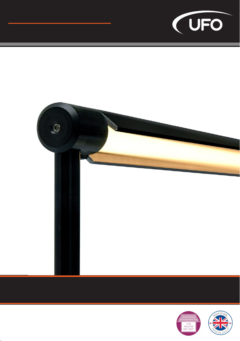
Thank you for purchasing this UFO Apollo lighting system.
Please read these instructions fully before performing any installation, operation or maintenance on the
system and before connecting power to your Apollo lighting system. Follow all warnings and instructions
carefully.
Please keep this manual for future reference.
The UFO Apollo is a configurable LED lighting system which has been specifically designed for ease-of-use
in many installation environments. Available in a variety of lengths and heights, with a black or silver finish
and with tuneable colour-temperature which can be adjusted between 1800K and 6500K.
Please carefully follow the warnings and information below and throughout this manual. Failure to do so
could lead to functional and/or structural failure of the Apollo system, causing damage to the Apollo
system and to adjacent items, fixtures and fittings. UFO will accept no responsibility for such failures, nor
damage caused as a result, and this would also invalidate the UFO warranty.
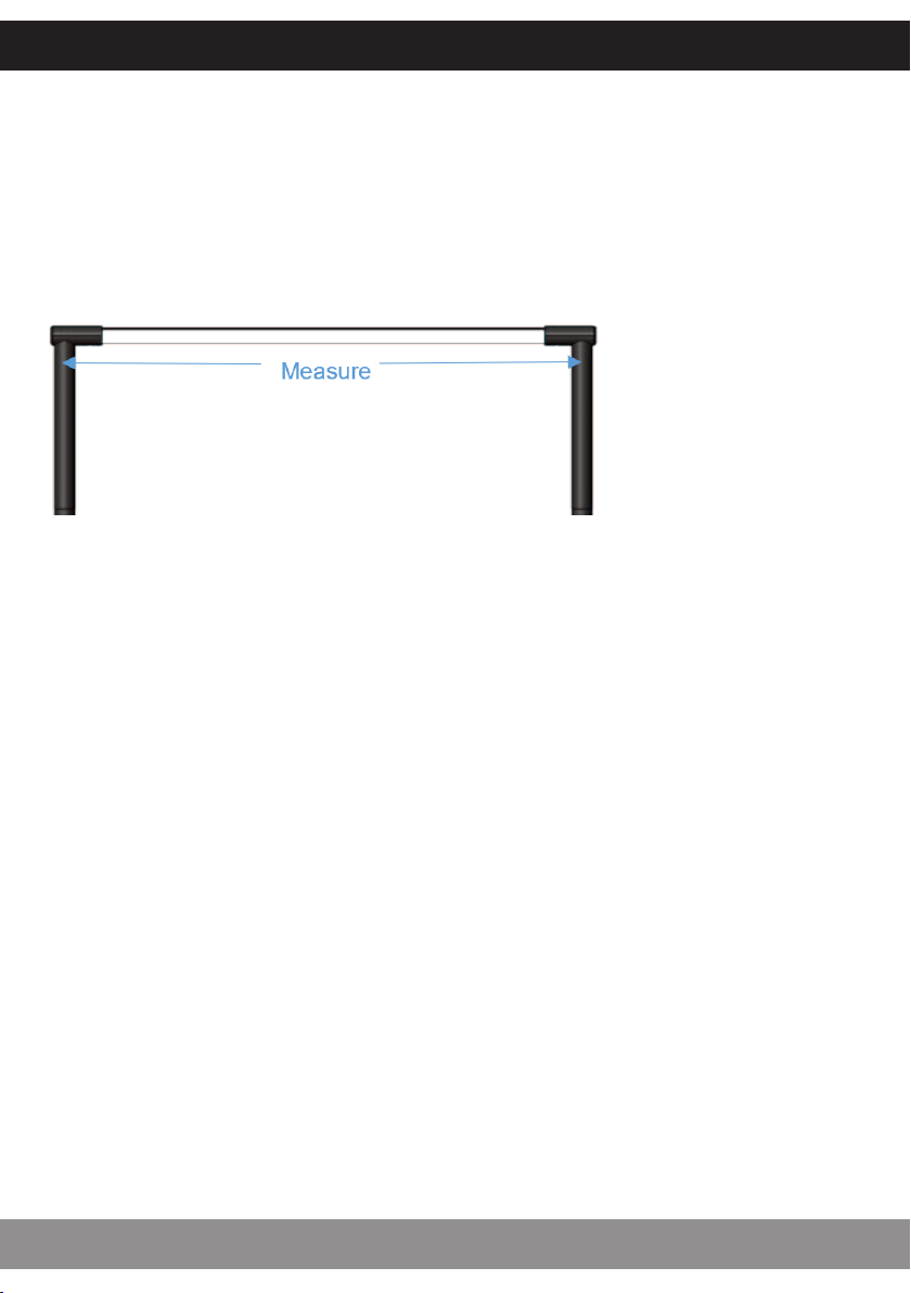
Apollo systems must be installed and used only in accordance with the UFO-supplied system design and
in accordance with the assembly & installation instructions in this manual.
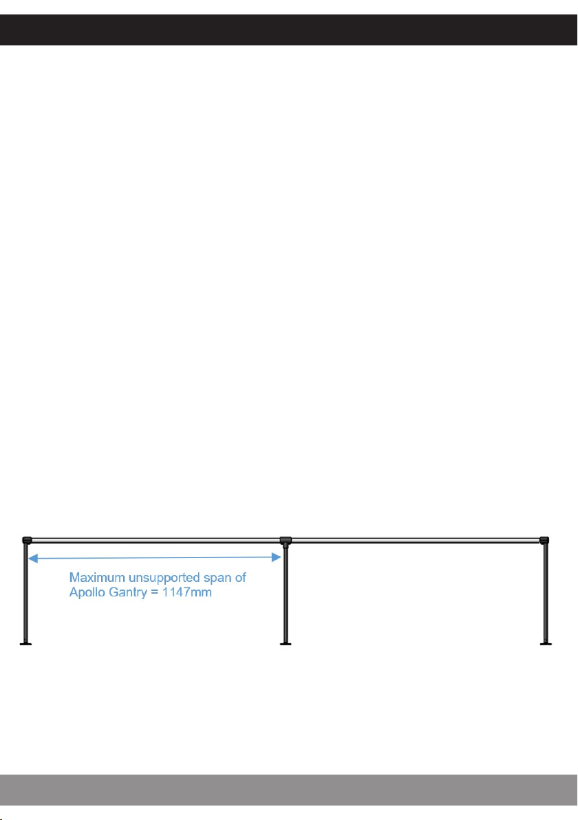
The UFO Apollo bodies and legs are designed and assembled cut to length by UFO and cannot be cut or
modified on site. Any attempt to cut or modify these products will invalidate warranty for the complete
UFO Apollo installation.
Apollo LED fittings operate from a constant-voltage, 24V DC supply. They should not be connected to a
constant-current driver. Apollo LED fittings are only dimmable with an appropriate constant-voltage
dimmer driver. Constant-current and constant-voltage LEDs cannot be intermixed on the same driver.
WARNING – These constant-voltage LED fittings operate on a 24V DC supply only. Connecting these fittings
to a dierent voltage supply is likely to cause malfunction and may even result in catastrophic damage to
the LED devices within them. Always check the output voltage of the PSU/driver to ensure correct output
voltage prior to powering up the system.
Ensure also that the selected power supply has suicient power capability for the length of LED tape/track
being driven and also voltage drop in the supply cable. The LED tape will generate a load depending on
type fitted and tape length as detailed below
• Fixed colour-temperature (2700K, 3000K or 4000K) = 14.4 Watts per metre
• Tuneable colour-temperature (1800K to 6500K) = 12 Watts per metre
The Apollo system is suitable for indoor/dry areas only and must not be installed in damp or wet
conditions.
WARNINGS AND IMPORTANT SAFETY INFORMATION

OUTPUT CAPACITY
3
UFO LIGHTING
UNPACKING &COMPONENT PARTS
3
Very carefully unpack the shipment – parts require gentle handling to avoid marking or damage.
Particular care must be taken with the Plug & Play Gantry, which comes completely assembled.
Check all component parts and accessories against your order.
APOLLO GANTRY COMPONENT PARTS APOLLO LINEAR WAND COMPONENT PARTS

POWER SUPPLIES &ASSOCIATED COMPONENTS
APOLLO USER GUIDE
4
IMPORTANT
DO NOT CONNECT POWER TO YOUR APOLLO SYSTEM UNTIL ALL PARTS ARE FULLY CONNECTED
AND YOU HAVE CHECKED ALL YOUR WIRING IS CORRECT AS PER THE UFO-SUPPLIED DESIGN
DRAWINGS.
UFO 24VDC PSU
The PSU shown is an example of a UFO approved 24V IEC
mains lead device, catering for UK,
European and USA mains supplies.
Ensure the power supply used has suicient power output
for the length and type of track being powered. Apollo re-
CONTROL OPTIONS
The Apollo system can be dimmed via a variety of devices, as listed below.
Ensure that any controllers used are suitable constant-voltage devices.
• Standard – no dimming
• Manual dimming
• Casambi Bluetooth dimming
• Eulum Xicato enabled Bluetooth
• Dali dimming
• DMX dimming
• 0-10V dimming
• RF remote dimming
See also wiring section below.
APOLLO PSU JUNCTION BOX
One of these boxes is normally required, in conjunction
with a suitable UFO approved 24V PSU, to power one or
more Apollo Gantries and/or Linear Wands. See Wiring
section later in this manual for more information.
NOTE: Multiple systems should only be connected to a sin-
gle Apollo PSU junction box if they are being controlled to-
gether and the connected PSU is able to supply suicient
power. Apollo systems require 14.4W per metre for fixed
colour-temperatures; 12W per metre for tuneable.

Standard Gantry legs are detached for shipping, so will require to be refitted.
Plug & Play Gantries will be supplied fully assembled as the legs are not removable.
OUTPUT CAPACITY
3
UFO LIGHTING
ASSEMBLY &INSTALLATION
5
STANDARD GANTRY SYSTEM ASSEMBLY
1. Very carefully (the component parts, cables etc are
easily damaged), feed the Apollo cable through the top of
one of the legs as shown. The top of the leg is the end
with the notch and cut-out slot.
2. With the cut-out slot facing
towards the Apollo’s main body
(see ‘a’ in image), slowly push the
leg into the gantry corner, while
gently feeding the cable through
the leg as you do so (see ‘b’ in
image). Ensure the cable does not
get snagged, which will prevent
the leg inserting fully and could
cause damage
3. Once the leg is fully inserted,
secure using an M3x3mm grub
screw – supplied, inserted into the
end of the gantry corner (see ‘c’ in
image). Tighten fully, but do not
overtighten.
4. Procedure for assembly of a
non-cable end is essentially the
same, except made simpler by the absence of the cable –
again ensure that the cut-out on the leg faces towards
gantry body.

ASSEMBLY &INSTALLATION
APOLLO USER GUIDE
6
ADDITIONAL ASSEMBLY FOR LONGER CUSTOM LENGTHS*
1. Remove the non-cable end of the Gantry.
2. Slide the Gantry middle-support(s) onto the Gantry.
3. Position the support(s) equidistantly on the Gantry body, following the design drawing
supplied by UFO. Ensure that there is never more than 1147mm of Gantry span unsupported
(extra supports advisable for unsupported spans of 900mm).
4. Use 2x M3x3mm grub screws to fix each middle support to the Apollo body, once correctly
positioned. Do not overtighten. Some further adjustment may be required when Gantry is fitted
in its final position to ensure all legs are straight and not mechanically stressed.
5. Push top of middle leg into middle support and use 3x M2x2mm grub screws to secure leg.
Do not overtighten.
6. Insert bottom of middle leg into foot and once correctly positioned, use 3x M2x2mm grub
screws to fix each middle support to the foot. Do not overtighten. Loosen grub screws from
steps above and re-adjust positions of the various components if required to ensure all legs are
straight and not mechanically stressed, then retighten all grub screws.
An example of an assembled custom Gantry is shown below.
IMPORTANT SAFETY INFORMATION
Failure to provide correct support for the Gantry may cause the Gantry to bend/break, possibly
leading to structural and functional failure, with the possibility of damaging adjacent items.
* Not applicable to Plug & play Gantries, which will be supplied fully assembled as the legs are
not removable.

STANDARD GANTRY SYSTEM MOUNTING
7
UFO LIGHTING
There are 3 distinct methods of mounting the Apollo Gantry System:
method 1 - screw-down feet, method 3 - back nut, method 3 - plug & play.
STANDARD GANTRY SYSTEM MOUNTING
METHOD 1- SCREW DOWN FEET INSTALLATION
1. Before taking any measurements, ensure that each Gantry support leg is fitted correctly to the
body in its final position and locked into place using the grub screw(s).
2. Lay the Gantry on a flat surface and measure between the points shown below (to half way
across each leg). Be sure to measure close to the top to ensure accuracy. If there are more than
two legs (see below for further information on extra legs), repeat the process until all gaps have
been measured and noted.
3. Use the measurement(s) to mark the centre point of each of the feet on the surface where the
Gantry will be mounted. If there are more than two legs, ensure marks are in a straight line to
avoid straining the Apollo’s structural components.
4. For routing the cable, drill a 4mm hole through the mounting surface, centred at your mark, on
the end that will carry the cable (check below surface first, to ensure there is suicient clearance
and to check that the drill bit will not damage anything as it emerges).
5. Line up the centre of each foot with your mark, then mark the position of the foot’s screw
holes. Drill pilot holes into the mounting surface, then secure the feet to the surface with suitable
screws.
6. Fit the Gantry to the feet, passing the wire through the hole you have drilled and use 3x
M2x2mm grub screws (supplied) to secure each leg to its foot. Be careful not to overtighten the
grub screws – only just tight is suicient.

STANDARD GANTRY SYSTEM MOUNTING
APOLLO USER GUIDE
8
IMPORTANT - ADDITIONAL SUPPORT LEGS
Additional central support legs are required for unsupported spans of longer than 1147mm and
recommended for those greater than 900mm (total maximum Gantry length is 3000mm). If
required, these will be part of your system’s design and will be supplied. They must be firmly
secured and fitted correctly as per the UFO-supplied design drawings, in order to ensure correct
and safe operation of the Apollo, and to fulfil the warranty conditions.
BEAM ANGLE ADJUSTMENT
Aer installation, the angle of the light beam can be adjusted by loosening the adjustment grub
screw at each end (as well as on middle supports if fitted) and rotating the body. Tighten the
grub screws once the desired angle has been achieved, but do not overtighten.
IMPORTANT
360° rotation is possible, however do
NOT rotate the body more than 180° in
either direction, as this could damage
the electrical connections.

STANDARD GANTRY SYSTEM MOUNTING
9
UFO LIGHTING
METHOD 2- BACK NUT FEET INSTALLATION
1. Ensure that each Gantry support leg is fitted correctly to the body in its final position and
locked into place using the grub screws before any measurements are taken.
2. Lay the Gantry on a flat surface and measure between the points shown (to half way across
each leg). Be sure to measure close to the top to ensure accuracy. If there are more than two
legs, repeat the process until all gaps have been measured and noted.
3. Use the measurement(s) to mark the centre point of each of the feet on the surface where the
Gantry will be mounted. If there are more than two legs, ensure marks are in a straight line to
avoid straining the Apollo’s structural components.
4. Drill a 6mm hole through the mounting surface, centred at each of your marks (check below
surface first to ensure there is suicient clearance and to check that the drill bit will not damage
anything as it emerges).
5. Pass the threaded section of the foot through the hole in the mounting surface, securing it
with the nut below. Repeat for all feet. Tighten nuts, but do not overtighten..
6. Pass the wiring through the foot on one end and fit the Gantry legs to the feet, using 3x
M2x2mm grub screws (supplied) to secure each leg to its foot. Be careful not to overtighten grub
screws – only just tight is suicient.

STANDARD GANTRY SYSTEM MOUNTING
APOLLO USER GUIDE
10
IMPORTANT - ADDITIONAL SUPPORT LEGS
Additional central support legs are required for unsupported spans of longer than 1147mm and
recommended for those greater than 900mm (total maximum Gantry length is 3000mm). If
required, these will be part of your system’s design and will be supplied. They must be firmly
secured and fitted correctly as per the UFO-supplied design drawings, in order to ensure correct
and safe operation of the Apollo, and to fulfil the warranty conditions.
BEAM ANGLE ADJUSTMENT
Aer installation, the angle of the light beam can be adjusted by loosening the adjustment grub
screw at each end (as well as on middle supports if fitted) and rotating the body. Tighten the
grub screws once the desired angle has been achieved, but do not overtighten.
IMPORTANT
360° rotation is possible, however do
NOT rotate the body more than 180° in
either direction, as this could damage
the electrical connections.
Beam adjustment grub
screw positions

STANDARD GANTRY SYSTEM MOUNTING
11
UFO LIGHTING
METHOD 3- PLUG &PLAY GANTRY
Please note – Plug & Play Gantry legs are not removable from the Gantry
body, so your gantry will have all its legs fitted in their final positions on
arrival.
3. Use the measurements to mark the centre point of each of the feet on the surface where the
Plug & Play Gantry will be mounted. If there are more than two legs, ensure marks are in a
straight line to avoid straining the Apollo’s structural components.
4. Drill a 19mm hole through the mounting surface, centred at each
mark (check below surface first, to ensure there is suicient
clearance and to check that the drill bit will not damage anything as
it emerges).
5. Insert the Plug & Play feet into their holes, ensuring the cable has
been passed through the hole first (where applicable).
6. Mark the position of the base’s screw holes. Drill pilot holes into the
surface, then secure the feet to the mounting surface with suitable
screws.
7. Place cover over base and ensure magnets engage.
8. Insert all Plug & Play legs into sockets.
1. Check that each Gantry support leg is fitted correctly to the body in its final
position and locked into place using the grub screws before any measurements
are taken.
2. Lay the Gantry down on a flat surface and measure between the points shown below (to half
way across each leg). Be sure to measure close to the top to ensure accuracy. If there are more
than two legs, repeat the process until all gaps have been measured and noted.

LINEAR WAND MOUNTING
APOLLO USER GUIDE
12
METHOD 1- MAGNETIC MOUNTING
This method is suitable only for applications where the mounting surface is
able to provide a strong attraction for the Wand’s magnets.
IMPORTANT - SAFETY INFORMATION
Ensure, when magnetically mounting Linear Wands to the chosen surface, that the surface is
flat, clean, clear of obstructions and made of a suitable, magnetically attractive metal. Carefully
test the strength of the mounting to ensure it cannot fall o, slide etc., even if bumped or
shaken.
Failure to ensure a secure mounting may cause the Linear Wand to fall, which may damage the
Wand and adjacent items. UFO will accept no responsibility for such failures, nor damage
caused as a result, and this would also invalidate the UFO warranty.
IMPORTANT - ADDITIONAL MAGNETIC SUPPORTS
Additional central magnetic supports are required for those unsupported spans of longer than
1147m and recommended for those longer than 900mm and (total maximum Linear Wand
length is 2995mm). If required, these will be part of your system’s design and will be supplied.
They must be firmly secured and fitted correctly as per the UFO-supplied design drawings, in
order to ensure correct and safe operation of the Apollo, and to fulfil the warranty conditions.
To fit additional central supports, remove the non-cable end support, slide the central
support(s) on to the Wand and refit the end support. Position the central supports equidistantly,
then ensure all mountings are straight & level, and secure using grub screws but do not
overtighten.
BEAM ANGLE ADJUSTMENT
Loosen the grub screw on all magnetic mountings, adjust the wand to the required angle and
tighten both grub screws, but do not overtighten. Aer adjustment, lie the Linear Wand, mag-
nets down, on a flat surface to ensure all magnetic mountings are aligned at the same angle.
Failure to ensure the magnetic mountings are correctly aligned can lead to the Wand magnets
not making good contact with the metal surface and could lead to the Wand falling or sliding.
IMPORTANT NOTE – 360° light beam rotation
is possible, however do NOT rotate the body
more than 180° in either direction, as this
could damage the electrical connections.
Finally, magnetically mount the Linear Wand
to a suitable metal surface, which is clean and
free of obstructions.

LINEAR WAND MOUNTING
13
UFO LIGHTING
METHOD 2- MOUNTING CLIPS
Mounting clips can be used instead of magnetic mountings in a wide variety
of installations. Mounting clips can be screwed to virtually any strong, flat
surface, using suitable screws and fixings. The Linear Wand is then clipped
into place.
IMPORTANT - SAFETY INFORMATION
Ensure, when fitting clips to the mounting surface, that the material is sound and strong. Check
also that they are screwed in securely using the correct screws/fixings to suit the material into
which they are being fixed, and that the Wand is clipped in fully and correctly. Failure to do so
may cause the Linear Wand to fall, which could damage the Wand and adjacent items.
If more than two clips are being used, ensure also that they are positioned in a straight line. If
they are out of alignment, you may experience diiculties inserting the Linear Wand into the
clips, and this may also damage the Wand and/or clips and could cause the Wand to come
loose and fall.
Maximum unsupported overhang at the ends is 50mm.
IMPORTANT - ADDITIONAL MOUNTING CLIPS
Additional central mounting clips are required for unsupported spans of longer than 1147mm
and recommended for those greater than 900mm (total maximum Linear Wand length is
2995mm). These should be placed equidistantly between the end clips.
If required, these will be part of your system’s design and will be supplied. They must be fitted
correctly, as per the UFO-supplied design drawings, in order to ensure correct and safe
operation of the Apollo, and to fulfil the warranty conditions.
BEAM ANGLE ADJUSTMENT
Aer installation, the angle of the light beam can be adjusted by simply rotating the Linear
Wand, once installation is complete.
IMPORTANT NOTE – 360° rotation is possible, however do NOT rotate the body more than 180°
in either direction, as this could damage the electrical connections.
WARNING: magnetic mounting and surface mounting clips cannot be intermixed or used
together on the same Linear Wand

LINEAR WAND MOUNTING
APOLLO USER GUIDE
14
METHOD 3- FREESTANDING WAND
1. Drill a 4mm hole through the mounting surface for cable routing, centred at the Wand’s
selected position (check below surface first, to ensure there is suf-
ficient clearance and to check that the drill bit will not damage
anything as it emerges).
2. Line up the centre of the foot with the centre of your hole and
mark the position of the foot’s screw holes. Drill pilot holes into the
surface, then secure the foot to the surface with suitable screws.
3. Loosen grub screw in foot.
4. Insert the Standing Wand insert into the foot, ensuring that the slot
in the insert lines up with the foot’s grub screw.
5. Pass the Wand cable through the cable routing hole and insert the
Wand into the foot.
6. Rotate Wand to required position then tighten grub screw to se-
cure, but do not overtighten.
UFO will accept no responsibility for failures, nor damage caused
as a result of improper or inadequate installation, and this would also invalidate the UFO
warranty.

OPTIONAL COWL
15
UFO LIGHTING
The optional cowl can be clipped on to the Gantry, Linear Wand or Standing Wand if required to
reduce glare or to focus light spread.
The cowl reduces the beam angle from 100° to 70° and its angle can easily be adjusted.
UFO will normally supply cowls pre-cut to fit your Apollo system, should your requirements be
known when ordering/designing your system.
They can also however be supplied later, either pre-cut to your specified length, or as an
unfinished (maximum 3000mm) length for you to cut/trim and fit.

WIRING EXAMPLES - FIXED COLOUR TEMPERATURE
APOLLO USER GUIDE
16
Some examples of fixed colour temperature Apollo System connection options are shown on
the following 5 pages.
IMPORTANT
Ensure that the power supply used for each Apollo system has suicient power for the total
length of Apollo – minimum requirement for fixed colour-temperature = 24V DC, 14.4 Watts per
metre.
Most 24V constant voltage dimmers/drivers will work with the 24V constant voltage Apollo
systems. Schematic connection drawings for specific dimmers/drivers are available from
UFO on request.
DIRECT CONNECTION – SINGLE APOLLO SYSTEM
No dimming control with direct connection – when the power is connected, the LEDs always
operate at 100% power.

WIRING EXAMPLES - FIXED COLOUR TEMPERATURE
17
UFO LIGHTING
DIRECT CONNECTION – MULTIPLE APOLLO SYSTEMS
No dimming control with direct connection – when the power is connected, all connected LEDs

WIRING EXAMPLES - FIXED COLOUR TEMPERATURE
APOLLO USER GUIDE
18
DIMMER WIRING – SINGLE APOLLO SYSTEM
LEDs can be dimmed between 0-100% brightness.

WIRING EXAMPLES - FIXED COLOUR TEMPERATURE
19
UFO LIGHTING
DIMMER WIRING – MULTIPLE APOLLO SYSTEMS – SINGLE-CHANNEL
Single channel dimmer – all connected Apollo systems dim/brighten together.

WIRING EXAMPLES - FIXED COLOUR TEMPERATURE
APOLLO USER GUIDE
20
DIMMER WIRING – MULTIPLE APOLLO SYSTEMS – MULTI-CHANNEL
Multi-channel dimmer – Apollo systems can be dimmed or brightened independently.
Table of contents
Other UFO Lighting Equipment manuals

UFO
UFO UFO MIC100P-3 User manual

UFO
UFO Illuminator 150 CDMXG User manual

UFO
UFO NOVA DMX Specification sheet

UFO
UFO Sirius UFOSIRCW User manual

UFO
UFO Vega SLP-2700M User manual

UFO
UFO Nova Light Source Specification sheet

UFO
UFO MicroLED 1000P Specification sheet

UFO
UFO MBL2 User manual

UFO
UFO LUNA SLP-3000M User manual

UFO
UFO Sirius Series User manual

UFO
UFO MIC100PT-3 User manual

UFO
UFO LP5 LED Paver User manual

UFO
UFO MicroLED 4000P Specification sheet

UFO
UFO IP-02 Specification sheet

UFO
UFO MicroLED 3000 Specification sheet

UFO
UFO MicroLED 1000P Specification sheet

UFO
UFO UFO MER3000M User manual

UFO
UFO MIC4000x2 User manual

UFO
UFO MicroLED 4000P Specification sheet

UFO
UFO LPV2 User manual