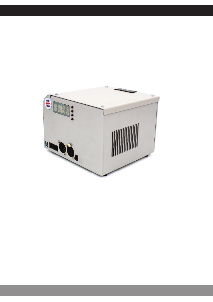
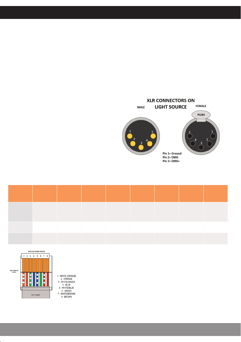
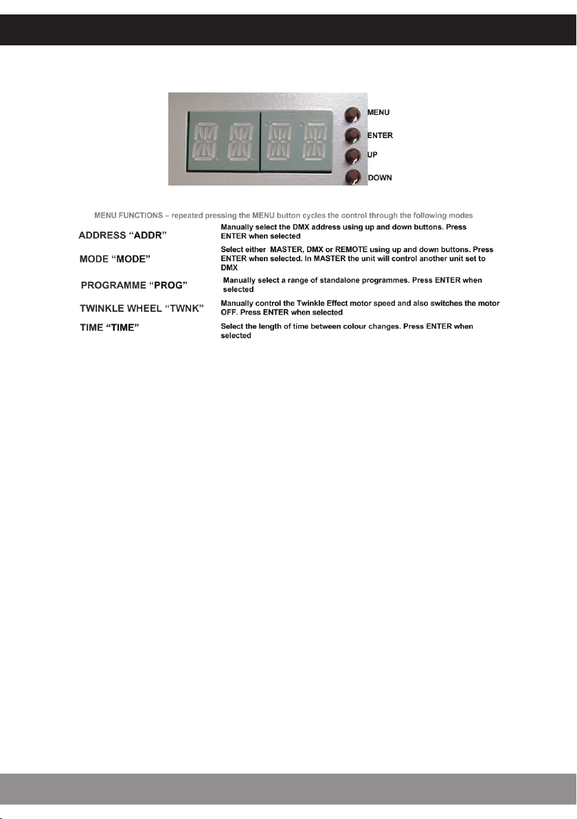
UFO Nova Light Source Specification sheet

PRODUCT USER GUIDE
Nova Light Source
PLEASE READ THIS USER GUIDE BEFORE INSTALLING, OPERATING
OR PERFORMING MAINTENANCE ON THE LIGHT SOURCE UNIT
E357731
Rev: C3

INTRODUCTION
NOVA USER GUIDE
2
Thank you for purchasing this UFO light source/luminaire.
To ensure that the light source is set up optimally and gives a long service life, please read this
user guide before installing, operating or performing any maintenance on the unit.
Please keep this User Guide for future reference. This User Guide is laid out in three sections
Installation -details on how to connect your luminaire
Operation - details how to programme and set up your luminaire
Maintenance - maintenance log, troubleshooting guide, technical specification
MODELS COVERED BY THIS USER GUIDE
UFO Nova DMX UFO Nova DMX-T UFO Nova DMX-TS
UFO Nova DMX-R UFO Nova DMX-TR UFO Nova DMX-TRS
IMPORTANT
This product must be installed in accordance with the applicable installation code, by a person
familiar with the construction and operation of the product, and the hazards involved.
These light sources are not mains dimmable.
The LED array and heatsink in this light source can be replaced when it reaches end of life.
Contact UFO for details.
Type Y Attachment: If the external flexible cable or cord of this luminaire or associated
PSU/driver is damaged, it shall be exclusively replaced by the manufacturer or his service agent
or a similar qualified person to avoid a hazard.
Location: Do not locate this light source closer than 200mm from any flammable surface.
Clearance / Ventilation: It is imperative that a gap of 200mm is le around the unit. This is to
allow air to circulate and prevent overheating. The location must have free ventilation and must
not have an ambient temperature higher than that specified for the luminaire.
Mounting: This luminaire comes with an integral mounting plate for securing the unit to a
vertical or horizontal surface. Refer to the instruction sheet supplied with the plate.
Warning: Never look directly at the luminaire through the fibre port of the light source.
Warning: The luminaire should be positioned so that prolonged staring into the
luminaire at a distance closer than 2.7 metres is not expected.

MOUNTING
This luminaire supplied with a separate mounting plate. If using the mounting plate refer to the
fitting instructions supplied with it.
INSTALLATION
3
UFO LIGHTING
POWER SUPPLY REQUIREMENTS
The Nova light source is powered from a 24V DC desk top power supply
unit. This PSU is an IEC input device catering for UK, European and USA mains supplies using
the relevant power cord.

CONNECTIONS
There are 3 connections required – the fibre port, the mains supply cable and, optionally, the
DMX control cable. The fibre port should be connected first. Connect and secure the fibre optic
connector into the 30mm diameter collar and secure using the M5 locking screw.
Connect the PSU to the DC input jack socket on the light source, and connect the IEC plug to the
PSU. Plug the mains plug into the electrical supply socket. Switch on power. The LED Indicator
will illuminate and the light source is ready for use.
If no light is produced consult the troubleshooting section.
As well as the standard XLR connectors for DMX connection, the Nova is also fitted with RJ45
connectors which also oer DMX capability. Details of these are below:
Pin No: 1 2 3 4 5 6 7 8
Colour White
Orange Orange White
Green Blue White
Blue Green White
Brown Brown
Funcon DMX+ DMXSpare Spare Spare Spare Ground Ground
XLR = Pin 3 Pin 2 Pin 1 Pin 1
Note:
It is recommended that a 120ohm terminating resistor be
connected across DMX+ and DMX- on the last light source
on the DMX universe or cable run.
Nova Master Slave function will only work when both
Master Nova and Slave Nova is set to address 001.
If DMX control is required, connect up
the DMX control cables to the XLR
sockets on the rear of the light
source. The pin out details for the
plugs are shown right.
INSTALLATION
NOVA USER GUIDE
4

REAR PANEL CONTROLS
The le hand display shows a rotating line when DMX data is received.
STANDALONE MASTER MODE
In this mode the light source (set to Master) can be used in two ways – either as a single
independent light source or in a Master/Slave configuration with several light sources connected
together using DMX cables. The Slave (set to DMX) will mimic whatever standalone
programme the Master light source is set to. All menu functions are available in Master mode.
Note: For Master/Slave to operate, both master & slave units must be set to address 001 only.
STANDALONE REMOTE MODE
Again in this mode the light source (set to Remote) can be used in two ways – either as a single
independent light source or in a Master/Slave configuration with several light sources connected
together using DMX cables. The Master colour sequences are controlled by a RF remote control
and again the Slave will mimic the Master light source.
DMX MODE
In this mode the light source (set to DMX) can be controlled either by another Nova in Master
mode or by a DMX controller.
OPERATION
5
UFO LIGHTING

NOVA REMOTE CONTROL UNIT
Descripon Details Comments
Power 2 x AAA baeries
Range 30 metres Measured in free space, may be aenuated by
obstrucons or other RF devices
Frequency 2.4GHz Approved for use in UK, USA and Europe
With the light source powered up as described
above, remove the rear cover on the remote control
unit. Taking care not to touch any of the front
buttons, insert the batteries.
If you touch the remote control buttons when
inserting the batteries it WILL eect the operation of
your remote control. If you do accidentally touch any
of the buttons, remove the batteries and start again.
Once the batteries are inserted do not use the
remote control for 3 seconds.
BATTERIES
The remote control unit is matched with the light source at the factory.
If the remote control is not matched or an additional or replacement remote control is required
carry out the “Matching Remote to Light Source” instructions as detailed later in this guide.
If a remote control is to be removed from control of a light source carry out the “Unmatching
Remote to Light Source” instructions as detailed later in this guide.
FURTHER INFORMATION
OPERATION
NOVA USER GUIDE
6

REMOTE CONTROL OPERATION
No. Descripon Funcon
1 Buon Power on
2 Buon Power off
3 Colour Ring Touch control all colours (white not available)
4 Indicator Indicates controller acve when buons pressed
5 Buon Increase colour cycle speed
6 Buon Increase brightness
7 Buon Decrease brightness
8 Buon Decrease colour cycle speed
9 Buon [Mode +] Step up through colour cycle programmes
10 Buon [Mode ] Step down through colour cycle programmes
10
9
8
7
6
5
4
3
2
1
MATCHING REMOTE CONTROL UNIT TO LIGHT SOURCE
Remove the power plug from the rear of the Light Source, then
replace and touch button 5 within 3 seconds, the Light Source
will “blink” twice slowly indicating that the Remote Controller
is matched to the Light Source.
Once the remote is matched, follow the procedure on page 10
to put the light source into remote programme mode. The
light source should then respond to remote commands.
UNMATCHING REMOTE CONTROL UNIT FROM LIGHT SOURCE
Remove the power plug from the rear of the Light Source, then
replace and touch and hold button 5 within 3 seconds and the
Light Source will “blink” 9 times indicating that the Remote
Controller is unmatched from the Light Source.
OPERATION
7
UFO LIGHTING
Note:
More than one Light Source controlled by one Remote
Controller will eventually run out of sync with each other (colour
cycle mismatch)

REMOTE CONTROL MODES AND FUNCTIONS
Mode Buttons – Do not work in a loop, i.e. touching the mode+ button will not eventually bring
you back to mode 1. To revert to mode 1, either touch mode – button repeatedly to step back
up through the mode numbers, or touch colour ring then mode+
Colour Ring –The colour ring can be used to select individual colours by touching the ring
and sliding your finger around the ring,
Brightness – brightness can be increased or reduced in any mode using buttons 6 & 7
Cycle Speed – speed of colour cycling in modes 3 to 14 can be adjusted using buttons 5 & 8
No. Mode Brightness Speed Comment
1 Stac white Adjustable Non adjustable
Touch colour ring then
mode + to enter this
mode at any me
2White and
colours mixed Adjustable Non adjustable
Colour ring control. Touch
colour ring to enter this
mode at any me
3 All colours fade Adjustable Adjustable No white
4 RGBW fade Adjustable Adjustable Red, green, blue, white
5RGBW snap Adjustable Adjustable Red, green, blue, white
6 7 colours snap Adjustable Adjustable White and colours mixed
7 2 colours snap Adjustable Adjustable Red and white
8 2 colours snap Adjustable Adjustable Blue and white
9 2 colours snap Adjustable Adjustable Green and white
10 1 colour flash Adjustable Adjustable Red
11 1 colour flash Adjustable Adjustable Blue
12 1 colour flash Adjustable Adjustable Green
13 1 colour flash Adjustable Adjustable White
14 All colours
snap/fade Adjustable Adjustable Random
OPERATION
NOVA USER GUIDE
8

REMOTE RANGE WALK TEST
Once the light source is fully installed carry out a complete range walk test and record the range
in the table below.
This information is essential for maintenance purposes to determine if the range/sensitivity is
reducing and also to record dead areas within the remote control units range due to RF
obstructions and/or RF interference.
Note: Where a light source has more than one remote control, reduction in operating range may
be experienced when both (or multiple) remote controls are used simultaneously.
Descripon Date Max Range
Controller 1
Controller 2
Controller 3
Dead Areas
OPERATION
9
UFO LIGHTING

PROGRAMMING
OPERATION
NOVA USER GUIDE
10

PROGRAMMING
OPERATION
11
UFO LIGHTING

STANDALONE OPERATION
Prog Funcon Effect
1 Colour 1 White
2 Colour 2 Red
3 Colour 3 Green
4 Colour 4 Blue
5 Colour 5 Yellow
6 Colour 6 Cyan
7 Colour 7 Magenta
8Snap colour change between
colours 1,2,3,4,5,6,7
Display colour for adjustable me (display
mer) and then snap to next colour
9Snap colour change between
colours 2,3,4,5,6,7
Display colour for adjustable me (display
mer) and then snap to next colour
10 Snap colour change between
colours 1,2,3,4
Display colour for adjustable me (display
mer) and then snap to next colour
11 Fade colour change between
colours 1,2,3,4,5,6,7
Display colour for adjustable me (display
mer) and then fade slowly to next colour
12 Fade colour change between
colours 2,3,4,5,6,7
Display colour for adjustable me (display
mer) and then fade slowly to next colour
13 Fade colour change between
colours 1,2,3,4
Display colour for adjustable me (display
mer) and then fade slowly to next colour
In standalone operation the twinkle wheel speed can be set using the menu/mode controls. The
twinkle wheel has two type options (programmed in the factory)
1.Un-segmented random holed wheel rotating continuously in one direction. When stopped the
wheel will still obscure the fibre optic common end.
2.Segmented random holed wheel rotating in twinkle mode either side of a clear segment. When
stopped the wheel segment will align with the fibre optic common end ensuring maximum light output
OPERATION
NOVA USER GUIDE
12

DMX CHANNEL OPERATION
The Nova DMX occupies 6 DMX channels as detailed below.
Channel Funcon Values
1Red 05 off/ 6255 min to max
2 Green 05 off/ 6255 min to max
3 Blue 05 off/ 6255 min to max
4 White 05 off/ 6255 min to max
5 Twinkle Wheel 05 off/ 6255 slow to fast
6 LED and Fan 0250 on / 251255 off
Note: the fan is controlled by a temperature circuit on the LED driver PCB – switching the fan on
and o to optimise LED Junction temperature.
Date Maintenance Undertaken
Note: A record of all maintenance MUST be kept in the table above, indicating what maintenance
was undertaken and when. This MUST be dated for warranty purposes.
OPERATION
13
UFO LIGHTING
MAINTENANCE

Problem Probable Cause(s) Remedy
Light source dead,
LED indicator on PSU
not illuminated
Main supply offCheck supply and reinstate
Loose mains plug Check plug
PSU faulty Replace PSU
Unit dead – LED
indicator on PSU illu
minated, LCD display
on light source not
illuminated
Loose DC plug Check plug
PSU faulty Check PSU output / replace PSU
Light source faulty Contact UFO
Light source no light
output, but LCD
display on light
source is illuminated
If programme Mode is set to “REMO”, light
source may have been switched offusing RF
remote control
Switch array on using RF remote control
LED array/driver faulty Contact UFO
RF remote controller
range reduced
Remote baeries failing Replace baeries as per User Guide
Another RF device causing interference Check for another RF device in same area
RF remote control needs reseng Remove and reinsert baeries as per User Guide
RF remote failing Replace remote
Light source receiver failing Replace light source
Light source won’t
respond to RF
remote controller
Light source not in Remote mode Check mode programming and set to “REMO”
Remote baeries failed Replace baeries as per User Guide
RF remote control needs reseng Remove and reinsert baeries as per User Guide
RF remote failed Replace remote
Light source receiver failed Replace Light Source
Not responding to
DMX – no rotang
symbol on LCD
display
Light source not in “DMX”mode Check mode programming and set to “DMX”
DMX address incorrectly set Change address on light source or DMX controller
No DMX signal from controller Check DMX controller for correct seng
Wiring fault on DMX cables/connecons Check cable connecons and repair as necessary
DMX driver failure Contact UFO
Not fully responding
to DMX – some but
not all colours con
trollable, no rotang
symbol on LCD
display
Light source address out of range – not 6
available channels on DMX controller
Change address on light source or DMX controller
to make 6 channels available
Not responding to
DMX – no light
output, rotang
symbol on LCD
display
Incorrect address set on light source or
controller Check addresses
No values set in DMX channel Check DMX controller channel values
Channel 6 value high (251255) switching
offthe array Reduce channel 6 value to <251
LED array/driver failed Contact UFO
Unit in Master mode
but twinkle wheel
not moving
Twinkle Motor switched offCheck “TWNK” mode seng
Internal component/motor failure Contact UFO
Poor light output on
fibre
Unit needs cleaning Clean the LED lens with a dry cloth
Clean fibre common end
Fibre port connector not plugged in
correctly
Ensure plugged in correctly and secured with
locking screw
TROUBLESHOOTING
NOVA USER GUIDE
14

TECHNICAL SPECIFICATION
15
UFO LIGHTING
Port Connector Size 30mm diameter
Fibre Type Glass / PMMA
Material/Finish Aluminium, powdercoated grey (RAL9006)
Dimensions (L x W x H) 183mm (7.2”) x 178mm (7.0”) x 128mm (5.0”)
Weight 1.91kg
Operang Environment Indoor use IP20
Min Ambient Temp. 10°C
Max Ambient Temp. +45°C
LED Array Type Custom RGBW array
LED Array Power 46W
LED Array Model Luxeon 36 LED Array
LED Array Life (L70, B10) 50,000 hours typical @ 25°C
Red 615nm \ 700lm
Green 530nm \ 1160lm
Blue 460nm \ 315lm
White 6500K \ 1435lm
Control Funconality DMX & manual dimming
DMX Funconality User addressable to 512
DMX Channels 6 channels
Colour Change
Funconality DMX, manual & remote control
Effects Wheels Opons &
Funconality Twinkle wheel controlled by DMX and manual
Supply Voltage 90264Vac
Mains Running Current 0.2A @ 240Vac
Mains Voltage VA rang 50VA
External PSU Type Meanwell, 24V, 2.5A, 60W
Motor Type Rotalink 25C13/YS0LPSL3E 12V 60:1
Fan Type Sunon, 80mm, 22dBA
RF Remote Frequency 2.4GHz
RF Remote Range 30m, depending on environment
RF Remote Power 2 x AAA baeries (supplied)

DESIGN SPECIFY BUILD INSTALL
United Kingdom •United States •Germany •Europe •UAE
UFO Licht GmbH
Friendsfactory AG \Gutenbergstraße 1
85737 Munchen \ Deutschland
+49 (0)9491 955880
www.ufo-licht.de
Universal Fiber Optics USA LLC
1749 Northgate Blvd
Sarasota \FL34234 \USA
941-343-8115
www.fiberopticlighting.com
Universal Fibre Optics Ltd
Home Place \Coldstream
TD12 4DT \UK
+44 (0)1890 883416
www.ufo.lighting
Other UFO Lighting Equipment manuals

UFO
UFO Quasar UFOQUA3080-A User manual

UFO
UFO MIC4000x2 User manual

UFO
UFO UFO MER3000M User manual

UFO
UFO MBL2 User manual

UFO
UFO Sirius Series User manual

UFO
UFO NOVA DMX Specification sheet

UFO
UFO Illuminator 150 CDMXG User manual

UFO
UFO MicroLED 4000P Specification sheet

UFO
UFO MicroLED 1000P Specification sheet

UFO
UFO Vega CM Specification sheet

UFO
UFO GEM SLP-3000M User manual

UFO
UFO MicroLED 100PT Specification sheet

UFO
UFO MicroLED 3000 Specification sheet

UFO
UFO MicroLED 4000P Specification sheet

UFO
UFO MBL1 User manual

UFO
UFO MIC100PT-3 User manual

UFO
UFO UFO MIC100P-3 User manual

UFO
UFO Sirius UFOSIRCW User manual

UFO
UFO Vega SLP-2700M User manual

UFO
UFO IP-02 Specification sheet