Thank you for purchasing this UFO light source/luminaire.
This innovative light source is designed to provide a flexible and creative lighting solution. A row
of three powerful LED arrays provides impressive illumination for design elements such as
shooting star eects, custom lighting eects, water eects, chasing special eects and firework
eects, while rear panel push-button controls and an LCD display provides outstanding ease of
use.
The Comet Light Source utilises industry standard protocols for the ultimate in control. It is
dimmable and you can also specify your preferred wheel: a 10 segment colour change wheel,
twinkle wheel, or a number of special eects wheels and custom light output collars can be
produced by UFO for you to enhance your desired eect. This is the perfect light source for
imaginatively illuminating decorative fibre optic eect lighting.
To ensure that the light source is set up optimally and gives a long service life, please read this
user guide before installing, operating or performing any maintenance on the unit.
Please keep this User Guide for future reference. This User Guide is laid out in three sections
Installation -details on how to connect your luminaire
Operation - details how to programme and set up your luminaire
Maintenance - maintenance log, troubleshooting guide, technical specification
INTRODUCTION
COMET USER GUIDE
2
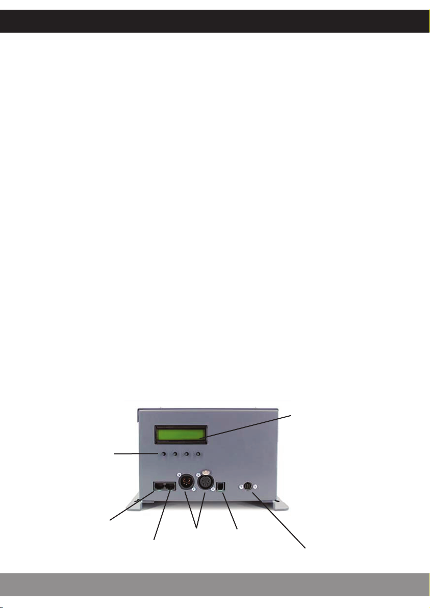
FEATURES
The Comet is a 60W white light LED Light Source with optional decorative or colour wheel
capability. The Comet LED Light Source driver PCB has all its control functionality fitted as
standard, available via rear panel connections, push buttons and LCD display.
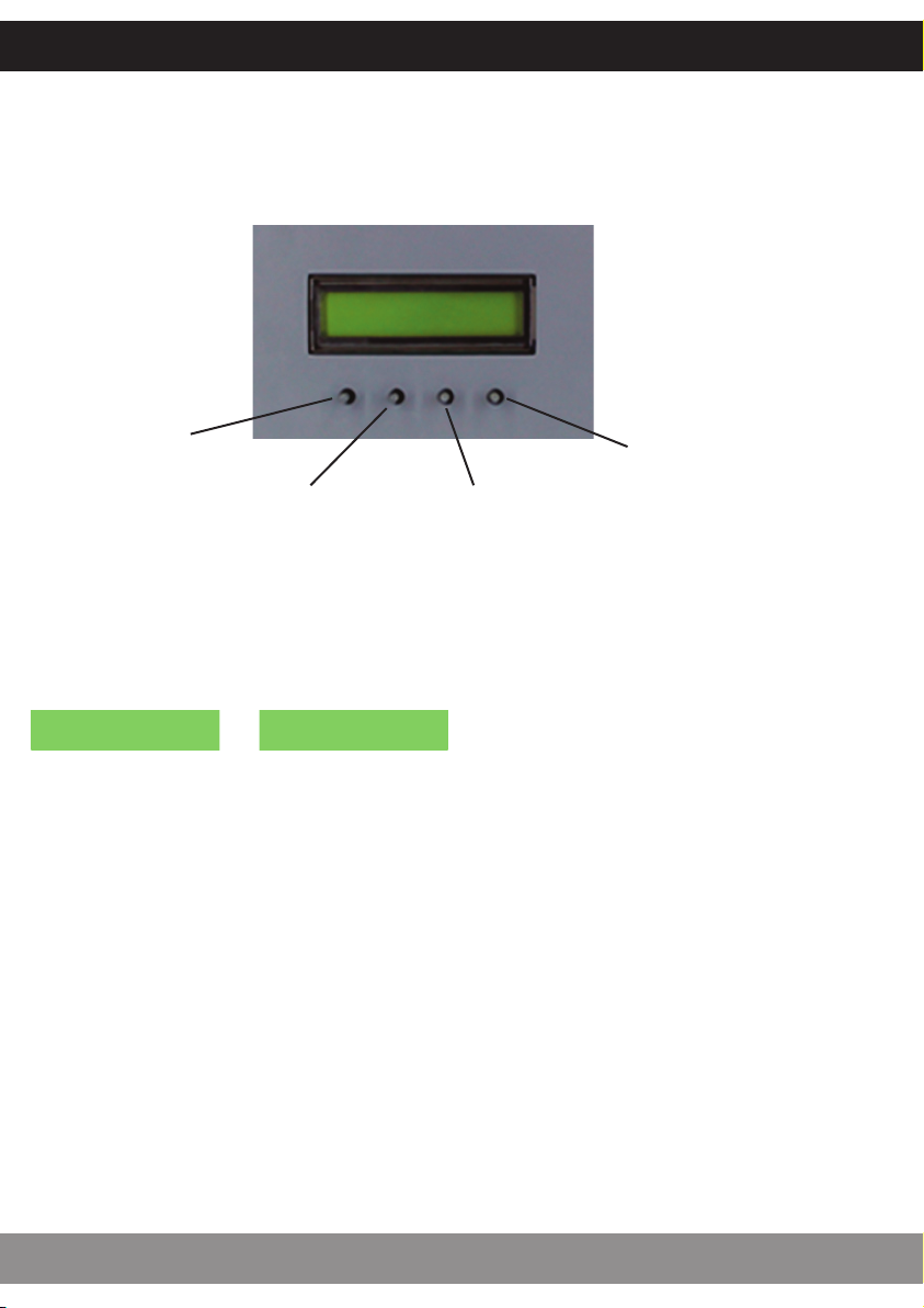
• Manual dimming using rear panel push button controls with status display
• 0-10V (current source – receiving) dimming
• 0-10V (current source – receiving) decorative wheel speed
• 1-10V (current sink – sending) dimming
• DMX dimming – 3 channels (white light dimming, wheel speed, initialise/reset/LED/fan on and
o)
• Manual decorative wheel with bi-directional motor speed control, or Stop setting, where an
open wheel segment can provide maximum light output.
• Master slave functionality – one COMET acting as master controlling slave COMET luminaires
via DMX links
The Comet LED Light Source is powered from a multi-voltage, external 48V Class 2 power supply
unit, which will be configured for your country’s mains supply.