manuals.online logo
Brands
  1. Home
  2. •
  3. Brands
  4. •
  5. Ultra-safe
  6. •
  7. Safety Equipment
  8. •
  9. Ultra-safe 96426SR Operator's manual

Ultra-safe 96426SR Operator's manual

WARNING!
This product is part of a personal fall
arrest system. The user must read
and follow the manufacturer’s
instructions for each component of
the system. These instructions must
e provided to the user of this
product. The user must read and
understand these instructions
efore using this product.
Manufacturer’s instructions must e
followed for proper use and
maintenance of this product.
Alteration or misuse of this product,
or failure to follow instructions may
result in serious injury or death.
1
USER INS RUC ION MANUAL
MODEL:
96426SR, 96424S, 96426S, 96426SYSR, 96513, 96516, 96516PH, 96516Y,
96516YCTPH 96516YPH, 96516YSR, 96516YSRADJ, S-96516, S-96516Y,
S-96516YSR, S-96516L, S-96516LYSR, S-96516LYCA, 96516LBB, 96516BB,
96516YBB, 96516LSD, 96516SD, 96516YSD, 96516HD, 96516YSRH, 96516YACAHD
DESCRIP ION: LANYARD WITH SHOCK PACKS, 3600 LB GATES
MEE S OSHA & ANSI Z359.1 | APPROVED FOR SHARP LEADING EDGE
1-800-850-5914
PHOENIX, AZ USA
WWW.UL RASAFEUSA.COM
MODEL:______________
_
SIZE: _________________
DA E: ________________
_
Anchorage: The anchorage to which this product is
attached must be capable of sustaining a static load in the
direction applied by the personal fall arrest system of at least
3600 lbs. with certification of a qualified person or 5000 lbs.
without certification. When more than one personal fall
arrest system is attached to the same structure, the strength
requirements stated above must be multiplied by the number
of personal arrest systems attached to the structure.
Plan your personal fall protection system. Before installing
and using this equipment, consider all factors affecting your
safety during use of this equipment.
Warning: Manufacturer's instructions supplied
with this product at time of shipment must be followed.
Failure to do so could result in serious injury or death.
Contact manufacturer if instructions are needed.
• Warnings and instructions must be read
and understood before using equipment.
• Equipment must be used by trained
personnel only.
• Users must understand all SHA regulations, ANSI
standards, and other relevant regulations and
standards pertaining to fall protection equipment.
This product is part of a personal fall
arrest system; a fall arrest system is
required if there is any risk that a
worker may fall from an elevated
position. It is a requirement that the
fall arrest system be used any time a
working height of six feet or more is
reached. Working height is defined as
the distance from the walking /
working surface to a
grade or lower level.
THE FOLLOWING IS RECOMMENDED
AS PART OF FALL ARREST SYSTEM
A. Shock A sor ing Lanyard
Material: Nylon
Warning tags located
in front and ack of shock
a sor er or located towards
hook, D-ring or eye end.
• Energy absorber resting force 900 lbs.
Plus 42 inch maximum extension.
• Rig lanyard to allow a maximum free fall distance
of not more than six feet.
• Connectors and anchorage points must be
compatible and able to support 5,000 lbs.
• Do not allow lanyard to contact sharp or abrasive
surfaces, sparks or temperature above 180 degrees.
• Snap hooks with gate openings larger than
one inch (1") must not be connected to D-rings
on harnesses and belts.
• Remove from service if any damage is detected.
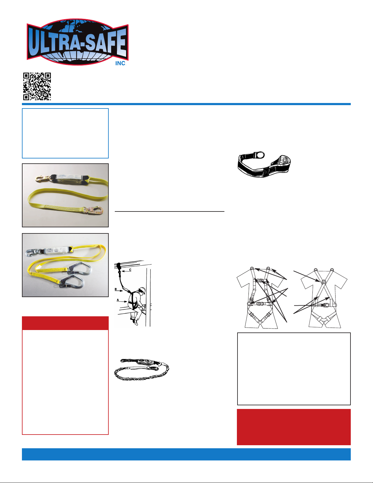
B. Anchorage connector
material: Nylon
Warning tags are
located towards hook,
D-ring or eye end.
•
Use energy absorbers or retractable lanyards
when hazard of free fall can occur.
• Connectors and anchorage points must be compatible
and able to support 5,000 lbs. Always work directly
under anchorage to avoid a swing fall injury.
• Anchorage and tie off points must be at a height
that will not allow a lower level to be struck should
a fall occur. Do not allow product to contact sharp
or abrasive surfaces, sparks or temperatures
above 180 degrees.
• Snap hooks with gate openings larger than
one inch (1”) must not be connected.
•
Remove from service if any damage is detected.
Same, but 100% ie-Off.
313L1
1.
2.
3.
4.
5.
6.
7.
1. Back 'D' ring is for fall arrest
2. Shoulder 'D' rings. (if present) are for retrieval use
only use locking snaps.
3. Side 'D' rings (if present) are for positioning only.
4. Front 'D' ring (if present) is for fall arrest
(foot first falls only, 2 foot max free fall), work
positioning, travel restraint or rescue
5. Hip attachment elements are for work positioning
or travel restraint
6. Visual load indicator
7. Park lanyard here
NOTE: See additional instructions on buckle adjustment
for proper fit. Maximum free-fall distance six feet or
energy absorber arresting force of 900 lbs per ANSI or
maximum fall arrest force of 1800 lbs per SHA.
Avoid lower level contact.
A ACH ENERGY
ABSORBER
ONLY O DORSAL
D-RING
MAXIMUM A ACHMEN DIS ANCE
WI H HOOK WI HOU HOOK
ACCEP ABLE DESIGNED RE AINER
DO NO
A ACH ENERGY
ABSORBER
O ANCHOR
When using lanyards commonly referred to
as "100% tie-off”, "Y" type, "double" or "twin
leg" shock absorbing lanyards. This
supplement provides additional information
on the use of these types of lanyards that are
used with a personal fall arrest systems.
Practices that must be followed in order to
use a 100% tie-off lanyard safely.
1. The shock absorber pack portion of the
lanyard assembly MUST be connected
to the back dorsal D-ring NLY, by way
of a double locking lanyard snap hook
(other connectors provided, consult
ULTRA-SAFE, INC.) connect shock
absorber directly to the dorsal D-ring.
2. Do not connect shock absorber to the
anchorage point at any time.
3. Do not connect the unused leg of the
lanyard assembly to any portion of the
full body harness, unless a specifically
designed lanyard snap hook loop
retainer is provided for this purpose.
4. When connecting from one anchorage
point to the next (traversing a vertical or
horizontal structure) do not connect to
an anchorage point further apart than,
the length of the lanyard.
5. When using a 100% tie-off lanyard
assembly, do not allow any part of the
lanyard to pass under arms or legs.
6. Connection of both lanyard legs to
separate anchorage points is
acceptable, as long as anchorage
points are within the length of the
lanyard.
2
ANCHORAGE: Select a rigid anchorage point that is capable of supporting the required loads. The
anchorage location must be carefully selected to reduce possible free fall and swing fall hazards and
to avoid striking an object during a fall. The anchorage should be generally level (horizontal) to prevent
the anchorage connector from sliding down an incline when in use, which could cause serious injury
to the user.
FREE FALL: Maximum free-fall distance six feet or energy absorber arresting force of 900 lbs per ANSI
or maximum fall arrest force of 1800 lbs per SHA.
CONNECTING TO ANCHORAGE OR ANCHORAGE
CONNECTOR: Always connect the energy
absorber end of the lanyard to the body support
(harness). Connect the lanyard end to the
anchorage or anchorage connector. Component
style energy absorbers should be connected to the body support first, then coupled to
the rest of the system. Some anchorage connector devices may be supplied with
permanently attached energy absorber. Use of an additional energy absorber or
energy absorbing lanyard with these types of subsystems is not recommended.
FALL CLEARANCE: Should a fall occur, there
must be sufficient clearance in the fall area
to arrest the fall before striking the ground or other object. Energy absorbers can extend the fall
arrest distance by up to 42 inches (106.7 cm). The illustration to the right shows how to estimate
fall clearance distance when using an energy absorbing lanyard or energy absorber subsystem.
ther factors may influence the required clearance distances. For example, using an energy
absorbing lanyard or energy absorber with a rope grab (fall arrestor) may require additional
clearance due to stretch in the lifeline or sliding of the rope grab on the lifeline during fall arrest.
Some full body harness models incorporate a sliding (positional) D-ring in the back as the fall
arrest attachment, movement of this D-ring during fall arrest can increase the fall clearance
distance required. Use caution when assembling system components that could act to extend the
fall arrest distance (and therefore fall clearance required). Refer to manufacturer's instructions
for each part of the system for more information on fall clearance.
Swing Fall
Hazard
Energy
Absorbing
Lanyard
Energy
Absorbing
Lanyard
Connecting
Subsystem
Anchorage
Connector
Anchorage
Connector
Anchorage
Connector
CHES LOOPS AND Y-LANYARDS
Anchor
Point
Nearest
bstruction
(Lower Level)
NO E:
Allow a minimum of
17’ from anchor
point to lower level.
Clearance to bstruction
1 1/2ft (.5m) Min Allowed
3
General -
1. Check for wear deterioration.
Before each use, carefully inspect your
complete Ultra-Safe system for signs of wear
or deterioration, or evidence of impact loading.
Visually inspect for loose threads, pulled rivets,
burns, cuts, distortions, abrasions, or other
evidence of chemical or physical deterioration
that may have weakened the material or
assembly.
2. Inspect hardware for malfunctions and cracks.
Check all snap hooks, buckles and D-Rings.
3. Destroy and replace all worn
or damaged equipment.
Immediately destroy and replace any component
which does not pass inspection.
Specific -
1. Stitching and we ing.
Check stitching for broken, burned, cut or pulled
stitches. Broken strands of webbing appear as
tufts on the webbing surface. To visually check for
damage caused by corrosives, heat, chemicals
and other conditions, hold the connecting device
with your hands six to eight inches apart. Bend
the webbing in an inverted "U" to cause surface
tension and expose problem areas. Inspect entire
length. For deceleration units, check the stitching
for broken, burned, cut or pulled stitches, and the
breakaway jacket for cuts, tears, broken stitches,
stretch marks or other evidence of impact load.
For aircraft-cable lanyards, check the full length
for breaks, burns or cuts in the vinyl covering and
the aircraft cable.
2. Check for roken strands.
Inspect rope lanyards for broken strands by
twisting the rope slightly to undo the braiding.
Inspect the entire lanyard in this manner.
Lanyards with broken strands must be discarded.
3. Inspect all snap hooks, D-Rings and
other metal parts.
Hardware must be checked for sharp edges and
cracks. Rollers should not be distorted in shape
and should roll freely. Check all parts, especially
corners and attachments points, for wear and
cracks.
4. Destroy and replace all worn or damaged
Ultra-Safe equipment.
If evidence of excessive wear, deterioration or
mechanical malfunction is observed, replace the
equipment immediately. Never work with worn or
damaged Ultra-Safe equipment. Using damaged
or worn equipment can cause injury or death.
5. The inspector is the most important part
of any inspection procedure.
Check all equipment thoroughly and follow all
safety procedures and guidelines. Do not take
any shortcuts', they could result in injury or death.
NOTE: Twisted rope, such as the nylon filament
and polyplus rope used in Ultra-Safe lanyards,
is subject to a condition known as "hockling",
which is similar to the twisting we often see
in a telephone handset cord. This can be
caused by a repetitive twisting movement
such as normal hand rotation in hooking
and unhooking, a lanyard dangling freely,
or by using the lanyard to suspend equipment.
Preventive measures include:
1) Never using a lanyard for towing or hoisting,
2) Inspection and smoothing out after each use,
3) Storing neatly. Some hockling is normal,
and in itself is not cause to discard
the lanyard.
Inspection Procedures
Serial Num er:
Model Num er:
Date Purchased:
Inspection Date Inspection Items Noted Corrective Action Maintenance Performed
Date of First Use:
INSPECTION AND MAINTENANCE LOG
IMPORTANT NOTE: SHA specifies that all employers covered by the ccupational Safety and Health Act are responsible for inspection and
maintenance of all tools and equipment used by employees, whether owned by the employees or by the company. All Ultra-Safe equipment
should be inspected before each use, and immediately removed from service if equipment does not pass inspection.
Approved By:
Approved By:
Approved By:
Approved By:
Approved By:
Approved By:
Approved By:
Approved By:
4
Inspection Date Inspection Items Noted Corrective Action Maintenance Performed
Approved By:
Approved By:
Approved By:
Approved By:
Approved By:
Approved By:
Approved By:
Approved By:
EXAMPLE OF TAGS
SERIAL NO.
L248590
DA E INI IALS
INSPEC ION
CHAR

This manual suits for next models

26

Other Ultra-safe Safety Equipment manuals

Ultra-safe M2-HPSY8Y Operator's manual

Ultra-safe

Ultra-safe M2-HPSY8Y Operator's manual

Ultra-safe 96805 Operator's manual

Ultra-safe

Ultra-safe 96805 Operator's manual

Ultra-safe MM-HNY8Y Operator's manual

Ultra-safe

Ultra-safe MM-HNY8Y Operator's manual

Ultra-safe 96305QL Operator's manual

Ultra-safe

Ultra-safe 96305QL Operator's manual

Ultra-safe 97424S Operator's manual

Ultra-safe

Ultra-safe 97424S Operator's manual

Ultra-safe UT-97516 Operator's manual

Ultra-safe

Ultra-safe UT-97516 Operator's manual

Ultra-safe 96516K Operator's manual

Ultra-safe

Ultra-safe 96516K Operator's manual

Ultra-safe UT-96516 Operator's manual

Ultra-safe

Ultra-safe UT-96516 Operator's manual

Ultra-safe US-5082ACSS Operator's manual

Ultra-safe

Ultra-safe US-5082ACSS Operator's manual

Ultra-safe 96305NK Operator's manual

Ultra-safe

Ultra-safe 96305NK Operator's manual

Ultra-safe 96305NTM Operator's manual

Ultra-safe

Ultra-safe 96305NTM Operator's manual

Ultra-safe US-5000C User manual

Ultra-safe

Ultra-safe US-5000C User manual

Ultra-safe 96516HD Operator's manual

Ultra-safe

Ultra-safe 96516HD Operator's manual

Ultra-safe US-HN8 Operator's manual

Ultra-safe

Ultra-safe US-HN8 Operator's manual

Ultra-safe TORINO LIGHT User manual

Ultra-safe

Ultra-safe TORINO LIGHT User manual

Ultra-safe US-1075CAEB Operator's manual

Ultra-safe

Ultra-safe US-1075CAEB Operator's manual

Popular Safety Equipment manuals by other brands

mercor mcr RPO-1 Operation and maintenance manual

mercor

mercor mcr RPO-1 Operation and maintenance manual

3M Bosun Chair User instructions

3M

3M Bosun Chair User instructions

MSA V-SHOCK PFL User instructions

MSA

MSA V-SHOCK PFL User instructions

Klein Tools KONSTRUCT Series instructions

Klein Tools

Klein Tools KONSTRUCT Series instructions

Plymovent PERSONALPRO User instructions

Plymovent

Plymovent PERSONALPRO User instructions

SafeWaze LATITUDE PRO SRL-P Series instruction manual

SafeWaze

SafeWaze LATITUDE PRO SRL-P Series instruction manual

Datalogic SG4 FIELDBUS Series instruction manual

Datalogic

Datalogic SG4 FIELDBUS Series instruction manual

TEUFELBERGER VOLTA Manufacturer's information and instructions for use

TEUFELBERGER

TEUFELBERGER VOLTA Manufacturer's information and instructions for use

Sagola 4240 Instruction manual / spare parts list

Sagola

Sagola 4240 Instruction manual / spare parts list

MSA G1 PremAire manual

MSA

MSA G1 PremAire manual

Climbing Technology TORSE instruction manual

Climbing Technology

Climbing Technology TORSE instruction manual

Reliance Roto-Loc 44 Series Instructions for use

Reliance

Reliance Roto-Loc 44 Series Instructions for use

Honeywell MILLER TURBOLITE+ Series user manual

Honeywell

Honeywell MILLER TURBOLITE+ Series user manual

SKYLOTEC WOODFIX AP-042 Instructions for use

SKYLOTEC

SKYLOTEC WOODFIX AP-042 Instructions for use

ROOM VALET Visual Alerting System instructions

ROOM VALET

ROOM VALET Visual Alerting System instructions

Petzl SCORPIO Instructions for use

Petzl

Petzl SCORPIO Instructions for use

ST Quadrat LUX-top FSE 2003 Installation and user instructions

ST Quadrat

ST Quadrat LUX-top FSE 2003 Installation and user instructions

Spinlock deckware Series manual

Spinlock

Spinlock deckware Series manual

manuals.online logo
manuals.online logoBrands
  • About & Mission
  • Contact us
  • Privacy Policy
  • Terms and Conditions

Copyright 2025 Manuals.Online. All Rights Reserved.