Ultra-safe UT-97516 Operator's manual

WARNING!
This produ t is part of a personal fall
arrest system. The user must read and
follow the manufa turers instru tions
for ea h omponent of the system.
These instru tions must be provided to
the user of this produ t. The user must
read and understand these instru tions
before using this produ t. Manufa tures
instru tions must be followed for proper
use and maintenan e of this produ t.
Alteration or misuse of this produ t, or
failure to follow instru tions may result
in serious injury or death.
1
USER INSTRUCTION MANUAL
MODEL:
UT-97516, UT-97516Y, UT-97516YBC, UTT-97516,
UTT-97516Y, UTT-97516YCT, UTT-97516YD, UTT-97516YCTD,
UTT-97516YCTDE
DESCRIPTION: IN-LINE SHOCK ABSORBER
3600LB GATE HOOKS
1 800 850 5914
PHOENIX, AZ USA
WWW.ULTRASAFEUSA.COM
MODEL:
_________________________
_
SIZE: ____________________
DATE: ___________________
_
Anchorage: The anchora e to which this product
is attached must be capable of sustainin a static
load in the direction applied by the personal fall
arrest system of at least 3600 lbs. With
certification of a qualified person or 5000 lbs.
without certification. When more than one
personal fall arrest system is attached to the
same structure, the stren th requirements stated
above must be multiplied by the number of
personal arrest systems attached to the
structure.
Plan: Your personal fall protection system.
Before installin and usin this equipment,
consider all factors affectin your safety durin
use of this equipment.
Warn ng: manufacturer's instructions supplied
with this product at time of shipment must be
followed. Failure to do so could result in serious
injury or death. Contact manufacturer if
instructions are needed.
• Warnin s and instructions must be read and
understood before usin equipment.
• Equipment must be used by trained
personnel only.
• Users must understand all OSHA re ulations,
ANSI standards, and other relevant
re ulations and standards pertainin to fall
protection equipment.
This product is part of a
personal fall arrest
system; a fall arrest
system is required if
there is any risk that a
worker may fall from an
elevated position. It is a
requirement that the fall
arrest system be used
any time a workin
hei ht of six feet or more
is reached. Workin
hei ht is defined as the
distance from the walkin /workin surface to a
rade or lower level.
The followin is recommended as part of fall
arrest system.
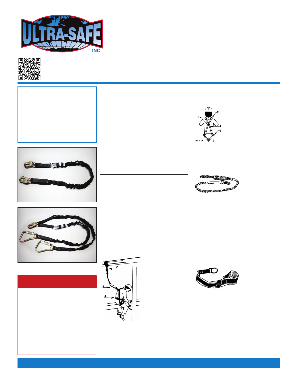
A. Full Body Harness Mater al: Nylon
1. Back D-rin is for fall arrest
2. Shoulder D-rin s (if present) are
for retrieval use only.
3. Side D-rin s (if present) are
for positionin only.
4. Warnin ta s.
Note: see additional instructions on buckle adjustment
for proper fit. Maximum free-fall distance six feet or
maximum fall arrest force of 1800 lbs. Avoid lower level
contact.
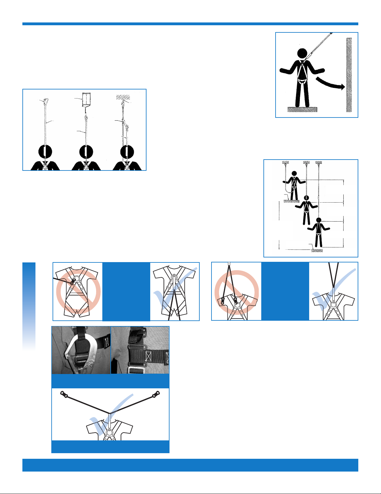
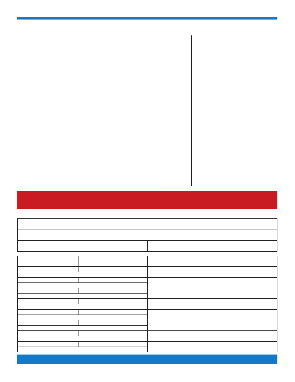
B. Shocks Absorb ng Lanyard Mater al: Nylon
Warn ng tags located
n front and back of
shock absorber or
located towards hook,
D-r ng or eye end.
• Ener y absorber restin force 900 lbs.
Plus 42 inch maximum extension.
• Ri lanyard to allow a maximum free fall distance
of not more than six feet.
• Connectors and anchora e points must be
compatible and able to support 5,000 lbs.
• Do not allow lanyard to contact sharp or abrasive
surfaces, sparks or temperature above 180 de rees.
• Snap hooks with ate openin s lar er than
one inch (1") must not be connected to d-rin s
on harnesses and belts.
• Remove from service if any dama e is detected.
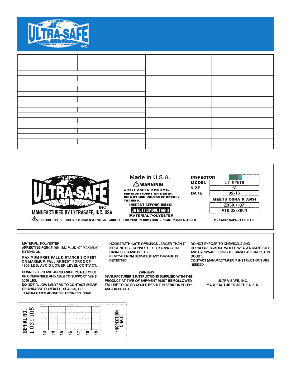
C. Anchorage connector mater al: Nylon
Warn ng tags are
located towards hook,
D-r ng or eye end.
•
Use ener y absorbers
or retractable lanyards
when hazard of free fall can occur.
• Connectors and anchora e points must be compatible
and able to support 5,000 lbs. Always work directly
under anchora e to avoid a swin fall injury.
• Anchora e and tie off points must be at a hei ht
that will not allow a lower level to be struck should
a fall occur. Do not allow product to contact sharp
or abrasive surfaces, sparks or temperatures
above 180 de rees.
• Snap hooks with ate openin s lar er than
one inch (1”) must not be connected.
•
Remove from service if any dama e is detected.
Same, but 100% Tie Off.
313L4

ATTACH ENERGY
ABSORBER
ONLY TO DORSAL
D RING
MAXIMUM ATTACHMENT DISTANCE
WITH HOOK WITHOUT HOOK
ACCEPTABLE DESIGNED RETAINER
DO NOT
ATTACH ENERGY
ABSORBER
TO ANCHOR
When usin lanyards commonly referred to
as "100% tie-off”, "Y" type, "double" or "twin
le " shock absorbin lanyards. This
supplement provides additional information
on the use of these types of lanyards that are
used with a personal fall arrest systems.
Practices that must be followed in order to
use a 100% tie-off lanyard safely.
1. The shock absorber pack portion of the
lanyard assembly MUST be connected
to the back dorsal D-rin ONLY, by way
of a double lockin lanyard snap hook
(other connectors provided, consult
ULTRA-SAFE, INC.) connect shock
absorber directly to the dorsal D-rin .
2. Do not connect shock absorber to the
anchora e point at any time.
3. Do not connect the unused le of the
lanyard assembly to any portion of the
full body harness, unless a specifically
desi ned lanyard snap hook loop
retainer is provided for this purpose.
4. When connectin from one anchora e
point to the next (traversin a vertical or
horizontal structure) do not connect to
an anchora e point further apart than,
the len th of the lanyard.
5. When usin a 100% tie-off lanyard
assembly, do not allow any part of the
lanyard to pass under arms or le s.
6. Connection of both lanyard le s to
separate anchora e points is
acceptable, as lon as anchora e
points are within the len th of the
lanyard.
2
ANCHORAGE: Select a ri id anchora e point that is capable of supportin the required loads. The
anchora e location must be carefully selected to reduce possible free fall and swin fall hazards and
to avoid strikin an object durin a fall. The anchora e should be enerally level (horizontal) to prevent
the anchora e connector from slidin down an incline when in use, which could cause serious injury
to the user.
FREE FALL: Maximum free-fall distance six feet or maximum fall arrest force of 1800 lbs.
Avoid lower level contact.
CONNECTING TO ANCHORAGE OR ANCHORAGE
CONNECTOR: Always connect the ener y
absorber end of the lanyard to the body support
(harness). Connect the lanyard end to the
anchora e or anchora e connector. Component
style ener y absorbers should be connected to the' body support first, then coupled
to the rest of the system. Some anchora e connector devices may be supplied with
permanently attached ener y absorber. Use of an additional ener y absorber or
ener y absorbin lanyard with these types of subsystems is not recommended.
FALL CLEARANCE: Should a fall occur, there
must be sufficient clearance in the fall area
to arrest the fall before strikin the round or other object. Ener y absorbers can extend the fall
arrest distance by up to 42 inches (106.7 cm). The illustration to the left shows how to estimate
fall clearance distance when usin an ener y absorbin lanyard or ener y absorber subsystem.
Other factors may influence the required clearance distances. For example, usin an ener y
absorbin lanyard or ener y absorber with a rope rab (fall arrestor) may require additional
clearance due to stretch in the lifeline or slidin of the rope rab on the lifeline durin fall arrest.
Some full body harness models incorporate a slidin (positional) D-rin in the back as the fall
arrest attachment, movement of this D-rin durin fall arrest can increase the fall clearance
distance required. Use caution when assemblin system components that could act to extend the
fall arrest distance (and therefore fall clearance required). Refer to manufacturer's instructions
for each part of the system for more information on fall clearance.
Swin Fall
Hazard
Ener y
Absorbin
Lanyard
Ener y
Absorbin
Lanyard
Connectin
Subsystem
Anchora e
Connector
Anchora e
Connector
Anchora e
Connector
Free Fall Distance
6ft (1.6m) Max Allowed
Free Fall Distance
6ft (1.6m) Max Allowed
Free Fall Distance
6ft (1.6m) Max Allowed
Required Distance
below workin
surface to
nearest obstruction
Workin
Surface
Nearest Obstruction
Clearance to Obstruction
1 1/2ft (.5m) Min Allowed
CHEST LOOPS AND Y LANYARDS

3
General -
1. Check for wear deter orat on.
Before each use, carefully inspect your
complete Ultra-Safe system for si ns of wear
or deterioration, or evidence of impact loadin .
Visually inspect for loose threads, pulled rivets,
burns, cuts, distortions, abrasions, or other
evidence of chemical or physical deterioration
that may have weakened the material or
assembly.
2. Inspect hardware for malfunct ons and cracks.
Check all snap hooks, buckles and D-Rin s.
3. Destroy and replace all worn
or damaged equ pment.
Immediately destroy and replace any component
which does not pass inspection.
Spec f c -
1. St tch ng and webb ng.
Check stitchin for broken, burned, cut or pulled
stitches. Broken strands of webbin appear as
tufts on the webbin surface. To visually check for
dama e caused by corrosives, heat, chemicals
and other conditions, hold the connectin device
with your hands six to ei ht inches apart. Bent the
webbin in an inverted "U" to cause surface
tension and expose problem areas. Inspect entire
len th. For deceleration units, check the stitchin
for broken, burned, cut or pulled stitches, and the
breakaway jacket for cuts, tears, broken stitches,
stretch marks or other evidence of impact load.
For aircraft-cable lanyards, check the full len th
for breaks, burns or cuts in the vinyl coverin and
the aircraft cable.
2. Check for broken strands.
Inspect rope lanyards for broken strands by
twistin the rope sli htly to undo the braidin .
Inspect the entire lanyard in this manner.
Lanyards with broken strands must be discarded.
3. Inspect all snap hooks, D-R ngs and
other metal parts.
Hardware must be checked for sharp ed es and
cracks. Rollers should not be distorted in shape
and should roll freely. Check all parts, especially
corners and attachments points, for wear and
cracks.
4. Destroy and replace all worn or damaged
Ultra-Safe equ pment.
If evidence of excessive wear, deterioration or
mechanical malfunction is observed, replace the
equipment immediately. Never work w th worn or
damaged Ultra-Safe equ pment. Us ng damaged
or worn equ pment can cause njury or death.
5. The nspector s the most mportant part
of any nspect on procedure.
Check all equipment thorou hly and follow all
safety procedures and uidelines. Do not take
any shortcuts', they could result in injury or death.
NOTE: Twisted rope, such as the nylon filament
and polyplus rope used in Ultra-Safe lanyards,
is subject to a condition known as "hocklin ",
which is similar to the twistin we often see
in a telephone handset cord. This can be
caused by a repetitive twistin movement
such as normal hand rotation in hookin
and unhookin , a lanyard dan lin freely,
or by usin the lanyard to suspend equipment.
Prevent ve measures nclude:
1) Never usin a lanyard for towin or hoistin ,
2) Inspection and smoothin out after each use,
3) Storin neatly. Some hocklin is normal,
and in itself is not cause to discard
the lanyard.
Inspect on Procedures
Ser al Number:
Model Number:
Date Purchased:
Inspect on Date Inspect on Items Noted Correct ve Act on Ma ntenance Performed
Date of F rst Use:
INSPECTION AND MAINTENANCE LOG
IMPORTANT NOTE: OSHA specifies that all employers covered by the Occupational Safety and Health Act are responsible for inspection and
maintenance of all tools and equipment used by employees, whether owned by the employees or by the company. All Ultra-Safe equipment
should be inspected before each use, and immediately removed from service if equipment does not pass inspection.
Approved By:
Approved By:
Approved By:
Approved By:
Approved By:
Approved By:
Approved By:
Approved By:

4
Inspect on Date Inspect on Items Noted Correct ve Act on Ma ntenance Performed
Approved By:
Approved By:
Approved By:
Approved By:
Approved By:
Approved By:
Approved By:
Approved By:
EXAMPLE OF TAGS
This manual suits for next models
8
Other Ultra-safe Safety Equipment manuals

Ultra-safe
Ultra-safe US-1075CAEB Operator's manual

Ultra-safe
Ultra-safe US-HN8 Operator's manual

Ultra-safe
Ultra-safe 96516K Operator's manual

Ultra-safe
Ultra-safe 96305NTM Operator's manual

Ultra-safe
Ultra-safe UT-96516 Operator's manual

Ultra-safe
Ultra-safe 97424S Operator's manual

Ultra-safe
Ultra-safe 96805 Operator's manual

Ultra-safe
Ultra-safe M2-HPSY8Y Operator's manual

Ultra-safe
Ultra-safe US-5000C User manual

Ultra-safe
Ultra-safe 96305NK Operator's manual