manuals.online logo
Brands
  1. Home
  2. •
  3. Brands
  4. •
  5. Ultra-safe
  6. •
  7. Safety Equipment
  8. •
  9. Ultra-safe 96516HD Operator's manual

Ultra-safe 96516HD Operator's manual

WARNING!
his product is part of a personal fall
arrest system. he user must read and
follow the manufacturer’s instructions for
each component of the system. hese
instructions must be provided to the user
of this product. he user must read and
understand these instructions before
using this product. Manufacturer’s
instructions must be followed for proper
use and maintenance of this product.
Alteration or misuse of this product, or
failure to follow instructions may result in
serious injury or death.
1
MODEL:
_________________________
_
SIZE: ____________________
DATE: __________________
_
Same, but 100% Tie-Off.
313L6
USE INST UCTION MANUAL
DESC IPTION: LANYARD WI H SHOCK PACKS
3600 LB GA E HOOKS
MODEL:
96516HD, 96516YHD, 96516YC HD, 96516YC HDD,
96516YC HDDE
MEETS OSHA & ANSI Z359.1
APP OVED FO SHA P LEADING EDGE
1-800-850-5914
PHOENIX, AZ USA WATCH VIDEO 6 ON ULTRASAFEUSA.COM
An horage: The anchorage to which this product is
attached must be capable of sustaining a static load in
the direction applied by the personal fall arrest system
of at least 3600 lbs. with certification of a qualified
person or 5000 lbs. without certification. When more
than one personal fall arrest system is attached to the
same structure, the strength requirements stated
above must be multiplied by the number of personal
arrest systems attached to the structure.
Plan your personal fall prote tion system.
Before installing and using this equipment, consider
all factors affecting your safety during use of this
equipment.
Warning: Manufacturer's instructions supplied with
this product at time of shipment must be followed.
Failure to do so could result in serious injury or death.
Contact manufacturer if instructions are needed.
• Warnings and instructions must be read and
understood before using equipment.
• Equipment must be used by trained personnel only.
• Users must understand all SHA regulations, ANSI
standards, and other relevant regulations and
standards pertaining to fall protection equipment.
This product is part of a personal fall
arrest system; a fall arrest system is
required if there is any risk that a worker
may fall from an elevated position. It is a
requirement that the fall arrest system be
used any time a working height of six feet
or more is reached. Working height is
defined as the distance from the walking /
working surface to a grade or lower level.
THE FOLLOWING IS ECOMMENDED
AS PA T OF FALL A EST SYSTEM.
Note: See additional instructions on buckle
adjustment for proper fit. Maximum free-fall distance
six feet or maximum fall arrest force of 1800 lbs.
Avoid lower level contact.
Sho k Absorbing
Lanyard Material: Nylon
Warning tags lo ated
in front and ba k of
sho k absorber or
lo ated towards hook,
D-ring or eye end.
• Energy absorber resting force 900 lbs.
Plus 42 inch maximum extension.
• Rig lanyard to allow a maximum free fall distance
of not more than six feet.
• Connectors and anchorage points must be
compatible and able to support 5,000 lbs.
• Do not allow lanyard to contact sharp or abrasive
surfaces, sparks or temperature above 180 degrees.
• Snap hooks with gate openings larger than
one inch (1") must not be connected to D-rings
on harnesses and belts.
• Remove from service if any damage is detected.
An horage onne tor
material: Nylon
Warning tags are
lo ated towards hook,
D-ring or eye end.
•
Use energy absorbers or retractable lanyards
when hazard of free fall can occur.
• Connectors and anchorage points must be compatible
and able to support 5,000 lbs. Always work directly
under anchorage to avoid a swing fall injury.
• Anchorage and tie off points must be at a height
that will not allow a lower level to be struck should
a fall occur. Do not allow product to contact sharp
or abrasive surfaces, sparks or temperatures
above 180 degrees.
• Snap hooks with gate openings larger than
one inch (1”) must not be connected.
•
Remove from service if any damage is detected.
1.
2.
3.
4.
5.
6.
7.
1. Back 'D' ring is for fall arrest
2. Shoulder 'D' rings. (if present) are for retrieval use
only use locking snaps.
3. Side 'D' rings (if present) are for positioning only.
4. Front 'D' ring (if present) is for fall arrest
(foot first falls only, 2 foot max free fall), work
positioning, travel restraint or rescue
5. Hip attachment elements are for work positioning
or travel restraint
6. Visual load indicator
7. Park lanyard here
NOTE:See additional instructions on buckle adjustment for proper fit. Maximum free-fall
distance six feet or
energy absorber arresting force of 900 lbs per ANSI or maximum fall arrest
force of 1800 lbs per OSHA.
Avoid lower level contact.
ATTACH
ENE GY
ABSO BE
ONLY TO
DO SAL
D- ING
MAXIMUM ATTACHMENT DISTANCE
WITH HOOK WITHOUT HOOK
ACCEPTABLE DESIGNED ETAINE
DO NOT
ATTACH
ENE GY
ABSO BE
TO ANCHO
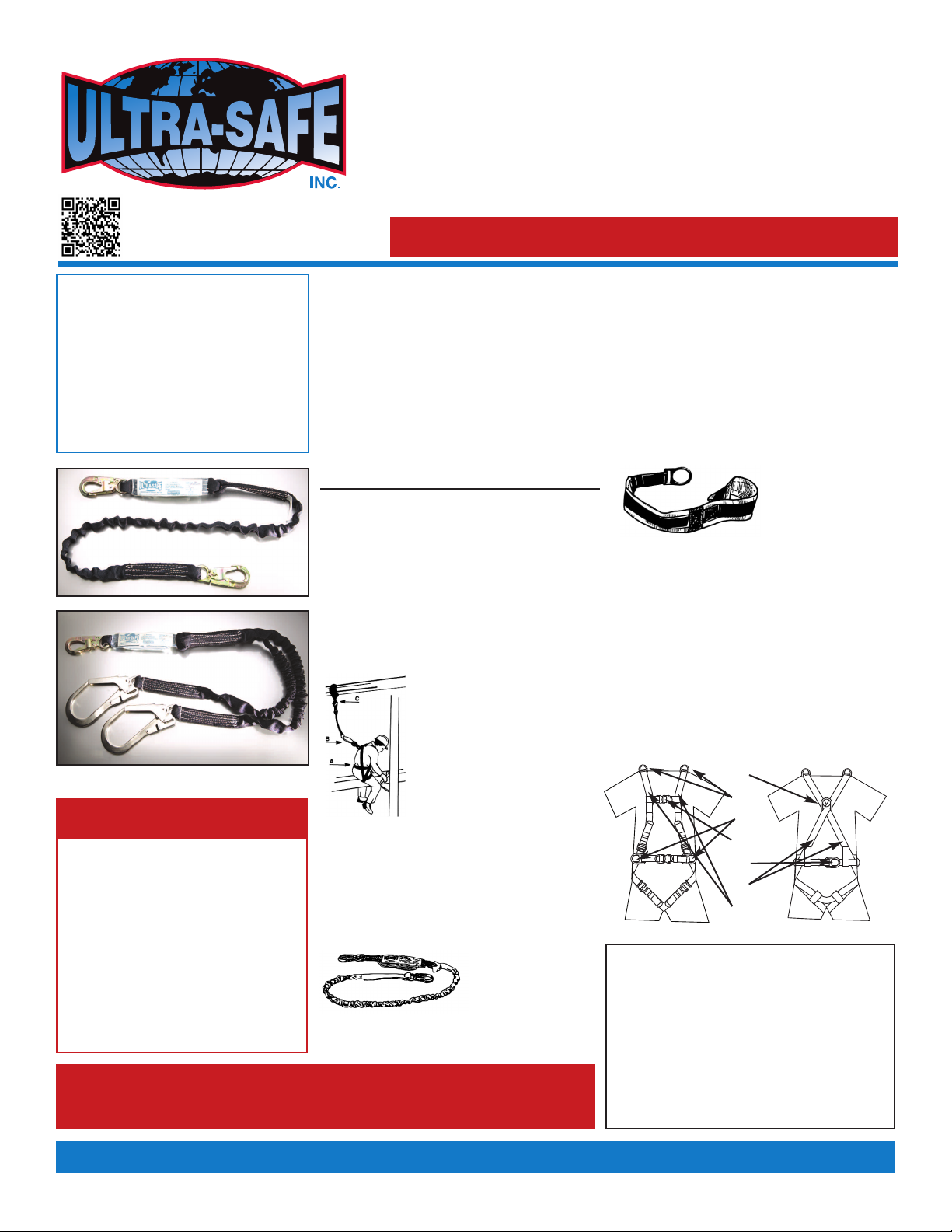
When using lanyards commonly referred to as "100% tie-
off”, "Y" type, "double" or "twin leg" shock absorbing
lanyards. This supplement provides additional information
on the use of these types of lanyards that are used with a
personal fall arrest systems. Practices that must be
followed in order to use a 100% tie-off lanyard safely.
1. The shock absorber pack portion of the lanyard
assembly MUST be connected to the back dorsal D-ring
NLY, by way of a double locking lanyard snap hook
(other connectors provided, consult ULTRA-SAFE, INC.)
connect shock absorber directly to the dorsal D-ring.
2. Do not connect shock absorber to the anchorage point
at any time.
3. Do not connect the unused leg of the lanyard assembly
to any portion of the full body harness, unless a
specifically designed lanyard snap hook loop retainer
is provided for this purpose.
4. When connecting from one anchorage point to the next
(traversing a vertical or horizontal structure) do not
connect to an anchorage point further apart than, the
length of the lanyard.
5. When using a 100% tie-off lanyard assembly, do not
allow any part of the lanyard to pass under arms or legs.
6. Connection of both lanyard legs to separate anchorage
points is acceptable, as long as anchorage points are
within the length of the lanyard.
MAINTENANCE, SE VICING, STO AGE:
Clean lanyard with water and a mild detergent solution. Wipe
off hardware with a clean, dry cloth, and hang to air dry. Do not
dry with heat source. Excessive buildup of dirt, paint, etc., may
occur and prevent the lanyard from working properly, and in
severe cases degrade the webbing or rope to a point where it
has become weakened and should be removed from service.
If you have any questions concerning the condition or cleaning
of your lanyard, doubts about putting it into service or require
more information, contact Ultra-Safe, Inc.
AFTE A FALL: Components which have been subjected to
the forces of arresting a fail must be removed from service
and destroyed.
ESCUE PLAN: When using this equipment, the employer
must have a rescue plan and the means at hand to implement
the rescue, as well as communicate that plan to users,
authorized persons, and rescuers.
COMPATIBILITY OF CONNECTO S:
IMP RTANT: Use only connectors that are suitable to each
application and are compatible with connecting elements.
ATTACHING A TIE-BACK LANYA D: Place the tie-back
lanyard over the anchoring structure. Ensure the lanyard is not
twisted. Adjust the sliding D-ring or choke back hook so it
hangs below the anchoring structure. Attach the lanyard end
hook to the floating D-ring or choke back hook. Ensure the
lanyard is cinched tight around the anchorage during use or
choke back hook directly back to body of lanyard.
2
ANCHORAGE: Select a rigid anchorage point that
is capable of supporting the required loads. The
anchorage location must be carefully selected to
reduce possible free fall and swing fall hazards
and to avoid striking an object during a fall.
The anchorage should be generally level
(horizontal) to prevent the anchorage connector
from sliding down an incline when in use, which
could cause serious injury to the user.
CONNECTING TO ANCHORAGE OR ANCHORAGE
CONNECTOR: Always connect the energy
absorber end of the lanyard to the body support
(harness). Connect the lanyard end to the
anchorage or anchorage connector. Component
style energy absorbers should be connected to
the' body support first, then coupled to the rest of
the system. Some anchorage connector devices
may be supplied with permanently attached
energy absorber. Use of an additional energy
absorber or energy absorbing lanyard with these
types of subsystems is not recommended.
FREE FALL: Maximum free-fall distance six feet or
energy absorber arresting force of 900 lbs per ANSI or
maximum fall arrest force of 1800 lbs per SHA.
FALL CLEARANCE: Should a fall occur, there
must be sufficient clearance in the fall area to
arrest the fall before striking the ground or other
object. Energy absorbers can extend the fall
arrest distance by up to 52 inches. The
illustration to the right shows how to estimate fall
clearance distance when using an energy
absorbing lanyard or energy absorber
subsystem. ther factors may influence the
required clearance distances. For example,
using an energy absorbing lanyard or energy
absorber with a rope grab (fall arrestor) may
require additional clearance due to stretch in the
lifeline or sliding of the rope grab on the lifeline
during fall arrest. Some full body harness models
incorporate a sliding (positional) D-ring in the
back as the fall arrest attachment, movement of
this D-ring during fall arrest can increase the fall
clearance distance required. Use caution when
assembling system components that could act
to extend the fall arrest distance (and therefore
fall clearance required). Refer to manufacturer's
instructions for each part of the system for more
information on fall clearance.
CAUTION: When working near moving
machinery, make sure Ultra-Safe components
are free from entanglement.
Swing Fall
Hazard
Energy
Absorbing
Lanyard
Energy
Absorbing
Lanyard
Connecting
Subsystem
Anchorage
Connector
Anchorage
Connector
Anchorage
Connector
WARNING: Do not alter or intentionally misuse this equipment. Consult Ultra-Safe, Inc. when using this equipment In combination with components or subsystems other than those
described in this manual. Some subsystem and component combinations may interfere with the operation of this equipment. Use caution when using this equipment around moving
machinery, electrical hazards, chemical hazards, sharp edges, or overhead materials that may fall onto the lanyard. Do not loop the lanyard around small structural members.
Failure to heed this warning may result in equipment malfunction, serious injury, or death. Any repair must be performed by Ultra-Safe, Inc. or an authorized repair station only.
• Connectors must be compatible with the anchorage
or other system components.
• Connectors must be compatible in size, shape, and strength
• Non-compatible connectors may unintentionally disengage
Do not allow gate to
contact anchorage
member.
Tie-off point diameter should be
large enough so that hook does
not contact anchor point.
Corre t In orre t
Anchor
Point
Nearest
bstruction
(Lower Level)
NOTE:
Allow a minimum
of 17’ 10” from
anchor point to
lower level.
Clearance to bstruction
1 1/2ft (.5m) Min Allowed
3
General -
1. Che k for wear deterioration.
Before each use, carefully inspect your
complete Ultra-Safe system for signs of wear
or deterioration, or evidence of impact loading.
Visually inspect for loose threads, pulled rivets,
burns, cuts, distortions, abrasions, or other
evidence of chemical or physical deterioration
that may have weakened the material or
assembly.
2. Inspe t hardware for malfun tions and ra ks.
Check all snap hooks, buckles and D-Rings.
3. Destroy and repla e all worn
or damaged equipment.
Immediately destroy and replace any component
which does not pass inspection.
Spe ifi -
1. Stit hing and webbing.
Check stitching for broken, burned, cut or pulled
stitches. Broken strands of webbing appear as
tufts on the webbing surface. To visually check for
damage caused by corrosives, heat, chemicals
and other conditions, hold the connecting device
with your hands six to eight inches apart. Bend
the webbing in an inverted "U" to cause surface
tension and expose problem areas. Inspect entire
length. For deceleration units, check the stitching
for broken, burned, cut or pulled stitches, and the
breakaway jacket for cuts, tears, broken stitches,
stretch marks or other evidence of impact load.
For aircraft-cable lanyards, check the full length
for breaks, burns or cuts in the vinyl covering and
the aircraft cable.
2. Che k for broken strands.
Inspect rope lanyards for broken strands by
twisting the rope slightly to undo the braiding.
Inspect the entire lanyard in this manner.
Lanyards with broken strands must be discarded.
3. Inspe t all snap hooks, D-Rings and
other metal parts.
Hardware must be checked for sharp edges and
cracks. Rollers should not be distorted in shape
and should roll freely. Check all parts, especially
corners and attachments points, for wear and
cracks.
4. Destroy and repla e all worn or damaged
Ultra-Safe equipment.
If evidence of excessive wear, deterioration or
mechanical malfunction is observed, replace the
equipment immediately. Never work with worn or
damaged Ultra-Safe equipment. Using damaged
or worn equipment an ause injury or death.
5. The inspe tor is the most important part
of any inspe tion pro edure.
Check all equipment thoroughly and follow all
safety procedures and guidelines. Do not take
any shortcuts', they could result in injury or death.
NOTE: Twisted rope, such as the nylon filament
and PolyPlus rope used in Ultra-Safe lanyards,
is subject to a condition known as "hockling",
which is similar to the twisting we often see
in a telephone handset cord. This can be
caused by a repetitive twisting movement
such as normal hand rotation in hooking
and unhooking, a lanyard dangling freely,
or by using the lanyard to suspend equipment.
Preventive measures in lude:
1) Never using a lanyard for towing or hoisting,
2) Inspection and smoothing out after each use,
3) Storing neatly. Some hockling is normal,
and in itself is not cause to discard
the lanyard.
Inspe tion Pro edures
Serial Number:
Model Number:
Date Pur hased:
Inspe tion Date Inspe tion Items Noted Corre tive A tion Maintenan e Performed
Date of First Use:
INSPECTION AND MAINTENANCE LOG
IMPORTANT NOTE: SHA specifies that all employers covered by the ccupational Safety and Health Act are responsible for inspection and
maintenance of all tools and equipment used by employees, whether owned by the employees or by the company. All Ultra-Safe equipment
should be inspected before each use, and immediately removed from service if equipment does not pass inspection.
Approved By:
Approved By:
Approved By:
Approved By:
Approved By:
Approved By:
Approved By:
Approved By:
4
Inspe tion Date Inspe tion Items Noted Corre tive A tion Maintenan e Performed
Approved By:
Approved By:
Approved By:
Approved By:
Approved By:
Approved By:
Approved By:
Approved By:
EXAMPLE OF TAGS
FO D OPS G EATE THAN 6’
ANSI/ASSE Z359.1
MATERIAL: NYLON / POLYESTER ENERGY
ABSORBER. ARRESTING FORCE 900 LBS.
TO 1800 LBS MAX PLUS 52” MAXIMUM EXTENSION. RIG
LANYARD TO ALLOW A MAXIMUM FREE FALL DISTANCE
OF NOT MORE THAN 12’ OR TO CONTACT A LOWER
LE EL.
CONNECTORS AND ANCHORAGE POINTS MUST BE
COMPATIBLE AND ABLE TO SUPPORT M.B.S. 5000 LBS.
DO NOT ALLOW SYNTHETIC LANYARD TO CONTACT
SHARP OR ABRASI E SURFACES, SPARKS OR
TEMPERATURES ABO E 180 DEGREES.
SNAP HOOKS WITH GATE OPENINGS LARGER THAN 1”
MUST NOT BE CONNECTED TO D-RINGS ON HARNESSES
AND BELTS.
REMO E FROM SER ICE IF ANY DAMAGE IS DETECTED.
WARNING
MANUFACTURER’S INSTRUCTIONS SUPPLIED WITH THIS
PRODUCT AT TIME OF SHIPMENT MUST BE FOLLOWED.
FAILURE TO DO SO COULD RESULT IN SERIOUS INJURY
AND/OR DEATH.
DO NOT EXPOSE TO CHEMICALS AND CORROSI ES
WHICH WOULD WEAKEN MATERIALS AND HARDWARE,
CONSULT MANUFACTURER, IF IN DOUBT.
CONTACT MANUFACTURER IF INSTRUCTIONS ARE
NEEDED.
ULTRA-SAFE, INC.
MANUFACTURED IN THE U.S.A.
SE IAL NO.
L248595
DATE INITIALS
INSPECTION
CHA T

This manual suits for next models

4

Other Ultra-safe Safety Equipment manuals

Ultra-safe UT-97516 Operator's manual

Ultra-safe

Ultra-safe UT-97516 Operator's manual

Ultra-safe US-HN8 Operator's manual

Ultra-safe

Ultra-safe US-HN8 Operator's manual

Ultra-safe TORINO LIGHT User manual

Ultra-safe

Ultra-safe TORINO LIGHT User manual

Ultra-safe 96805 Operator's manual

Ultra-safe

Ultra-safe 96805 Operator's manual

Ultra-safe US-5082ACSS Operator's manual

Ultra-safe

Ultra-safe US-5082ACSS Operator's manual

Ultra-safe 96305NK Operator's manual

Ultra-safe

Ultra-safe 96305NK Operator's manual

Ultra-safe US-5000C User manual

Ultra-safe

Ultra-safe US-5000C User manual

Ultra-safe MM-HNY8Y Operator's manual

Ultra-safe

Ultra-safe MM-HNY8Y Operator's manual

Ultra-safe UT-96516 Operator's manual

Ultra-safe

Ultra-safe UT-96516 Operator's manual

Ultra-safe 97424S Operator's manual

Ultra-safe

Ultra-safe 97424S Operator's manual

Ultra-safe M2-HPSY8Y Operator's manual

Ultra-safe

Ultra-safe M2-HPSY8Y Operator's manual

Ultra-safe 96305QL Operator's manual

Ultra-safe

Ultra-safe 96305QL Operator's manual

Ultra-safe 96516K Operator's manual

Ultra-safe

Ultra-safe 96516K Operator's manual

Ultra-safe 96426SR Operator's manual

Ultra-safe

Ultra-safe 96426SR Operator's manual

Ultra-safe 96305NTM Operator's manual

Ultra-safe

Ultra-safe 96305NTM Operator's manual

Ultra-safe US-1075CAEB Operator's manual

Ultra-safe

Ultra-safe US-1075CAEB Operator's manual

Popular Safety Equipment manuals by other brands

Sicame CATU AFG-1 Series manual

Sicame

Sicame CATU AFG-1 Series manual

BosStrap Side Slide instructions

BosStrap

BosStrap Side Slide instructions

Guardian 15220 instruction manual

Guardian

Guardian 15220 instruction manual

M-system 18YC instruction manual

M-system

M-system 18YC instruction manual

3M DBI-SALA 2104560 User instructions

3M

3M DBI-SALA 2104560 User instructions

Gunnebo WRIN STR Handle Product information

Gunnebo

Gunnebo WRIN STR Handle Product information

Dräger X-plore 2100 Instructions for use

Dräger

Dräger X-plore 2100 Instructions for use

CMC Rescue ENFORCER Instructions for use

CMC Rescue

CMC Rescue ENFORCER Instructions for use

Eaton BG2 Technical manual

Eaton

Eaton BG2 Technical manual

SafeWaze 021-4068 instruction manual

SafeWaze

SafeWaze 021-4068 instruction manual

Falltech 7291A User Instruction Sheet

Falltech

Falltech 7291A User Instruction Sheet

Petzl JOKO manual

Petzl

Petzl JOKO manual

3M ULTRA-LOK Series instruction manual

3M

3M ULTRA-LOK Series instruction manual

DoorKing 1601-567 installation instructions

DoorKing

DoorKing 1601-567 installation instructions

Sperian MILLER Grip 497 Operation and instruction manual

Sperian

Sperian MILLER Grip 497 Operation and instruction manual

MSA V-FLEX Use and maintenance instructions

MSA

MSA V-FLEX Use and maintenance instructions

Metacon-Next RGC / OHD-C installation instructions

Metacon-Next

Metacon-Next RGC / OHD-C installation instructions

3M Peltor SportTac manual

3M

3M Peltor SportTac manual

manuals.online logo
manuals.online logoBrands
  • About & Mission
  • Contact us
  • Privacy Policy
  • Terms and Conditions

Copyright 2025 Manuals.Online. All Rights Reserved.