Ultra-safe MM-HNY8Y Operator's manual

Should be used as part of an employee training program as
required by OSHA and is intended to meet the manufacturers
instructions as required by ANSI Z359.14-2014 CLASS B (SLE).
ANCHORAGE: The anchorage to which this product is attached
must be capable of sustaining a static load in the direction
applied by the personal fall arrest system of at least 3600 Ibs.
with certification of a qualified person, or 5000 Ibs. without
certification. When more than one personal fall arrest system
is attached to the same structure, the strength requirements
stated above must be multiplied by the number of personal
arrest systems attached to the structure.
PLAN: Your personal fall protection system before installing
and using this equipment. Consider all factors affecting your
safety during use of this equipment.
CAUTION: BEWARE OF PENDULUM SWINGS TO AVOID STRI ING AN
OBJECT OR CONTACT WITH A LOWER LEVEL, FAILURE TO FOLLOW
INSTRUCTIONS MAY RESULT IN SERIOUS INJURY.
FREE FALL: Ensure adequate clearance exists in your fall path
to prevent striking an object. When the safety retractable is
anchored above, a minimum of 4 ft. from the working level to
the lower level or nearest obstruction is recommended, if
anchored at foot level an additional 9 ft. clearance is needed.
Working load up to 300 lbs ANSI or 400 lbs OSHA. If worker is
over 300 lbs add 12” to safety factor to avoid lower level
contact. Avoid working where your lifeline may cross or tangle
with that of another worker. Do not allow the lifeline to pass
under your arms or between your feet. Never clip, knot, or
otherwise prevent the lifeline from retracting.
ARNING!
This product is part of a personal fall arrest system. The user must
read and follow the manufacturers instructions for each
component of the system. These instructions must be provided to
the user of this product. The user must read and understand these
instructions before using this product. Manufacturers instructions
must be followed for proper use and maintenance of this product.
Alteration or misuse of this product, or failure to follow
instructions may result in serious injury or death.
WIDEST SHARP LEADING EDGE APPROVED PRODUCT LINE IN THE INDUSTRY!
Approved for SHARP LEADING EDGE nd foot level drops.
3rd p rty certified by n ISO 17025 ccredited test
l bor tory. Lengths up to 110’.
313RL1S
USER INSTRUCTION MANUAL
DESCRIPTION:
SAFETY RETRACTABLE LANYARDS MADE WITH WIRE
ROPE / WEBBIN . ALSO AVAILABLE 100% TIE-OFF
MODEL:
M2-HPSY8Y, M2-HPSY8YCA, M2-HPSY8YABB, M2-HPSY8YCT,
US-HN8, MM-HNY8Y, MM-HNY8YCAS, US-HPS8, US-HPS11, US-HPS20,
US-HPS30, US-HPS40, US-HN10, US-HN15, US-HN20, US-HN30,
US-HN40, US-HN60, US-HN80, US-H110, US-H150, US-H210
MEETS OSHA & ANSI Z359.14 CLASS B (SLE)
1-800-850-5914
PHOENIX, AZ USA WATCH VIDEOS
1, 2, 8, 17, 26, 27, 28, 29 & 31
ON ULTRASAFEUSA.COM
FOR EXTRA
COMFORT
PROUDLY
MANUFACTURED IN
RELIABILITY YOU
CAN COUNT ON!
GERMANY

2
BEFORE EACH USE:
Inspect all your personal fall protection
equipment before each use. OSHA 1910.66 and
1926.502 and ANSI Z359.14 Class B (SLE)
requires an inspection before each use. The
use of American National Standards is
completely voluntary. Their existence does not,
in any respect, preclude anyone. ANSI requires
a formal documented inspection of fall
protection equipment to be completed by a
competent person other than the user, at a
minimum of once a year. More frequent
inspections by a competent person may be
required based on the severity of the
workplace conditions.
ULTRA-SAFE equipment is designed for use
with only ULTRA-SAFE approved components
and ULTRA-SAFE sub systems. Substitutions
or replacements made with non-approved
components or subsystems may jeopardize
compatibility of equipment and may affect the
safety and reliability of a complete system.
Personal fall arrest systems must meet
applicable local, state, and federal OSHA
requirements. Connectors (hooks. Carabiners.
and D-Rings) must be capable of supporting at
least 5000 Ibs. Do not use equipment that is not
compatible with the anchorage or other
system components. Connectors must be
compatible in size, shape, and strength. Self
locking snap hooks and carabiners are required
by ANSI Z359.14 Class B (SLE) and OSHA.
NOTE: Large throat opening snap hooks
should not be connected to standard size D-
Rings or similar objects which will result in a
load on the gate if the hook or D-Ring rotates
or twist. Large throat snap hooks are designed
for use on fixed structural elements such as
cross members or rebar that are not shaped in
a way that can capture the gate of the hook.
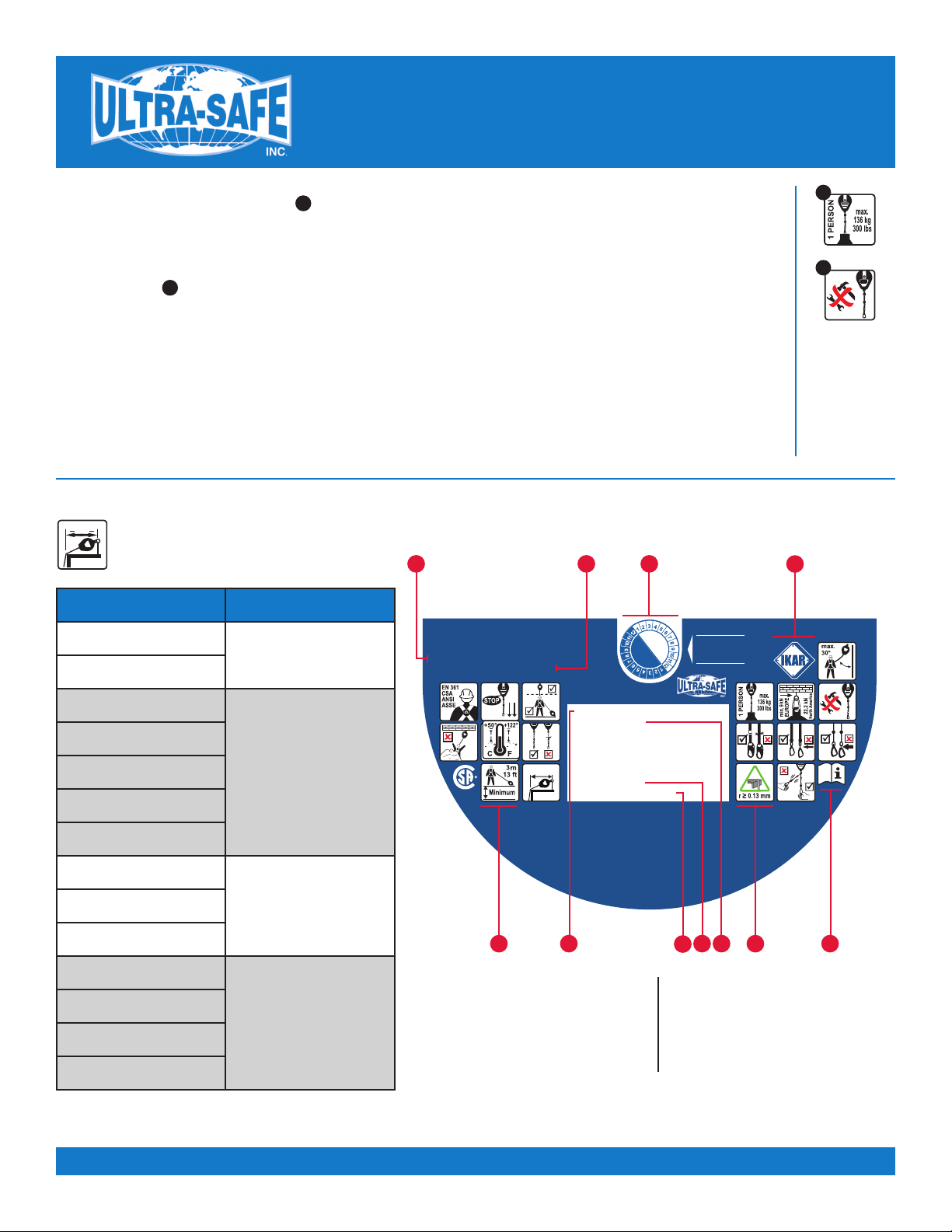
FALL: After a fall, equipment which has been
subjected to fall arrest forces MUST be
removed from service for inspection. Inspect
the entire safety retractable lanyard such as the
load / impact indicator. On web style find the
fold on the web to see if the stitching is broken
and the fold torn apart or for wire style check
the swivel snap hook to see if the RED indicator
was engaged. The safety retractable lanyard
must be removed from service and returned to
an authorized service station for repair, do not
re-stitch or repair..
ULTRA-SAFE®SAFETY RETRACTABLE DEVICE INSPECTION CRITERIA: The authorized person using this equipment sha , at a minimum comp y with manufacturer’s
instructions regarding the inspection, maintenance, and remova from service of the equipment. Equipment sha be inspected by the authorized person before each use.
Additiona y, inspections sha be conducted by a competent person other than the user. Inspection criteria for the equipment sha be set by the safety program administrator.
Documentation of equipment inspection sha be maintained by the safety program administrator. Inspections sha be conducted in interva s based on the type of use,
infrequent, moderate, and severe. If inspections revea defects, damage, stress, activated warning systems or inadequate maintenance, the equipment sha be permanent y
removed from service or undergo corrective maintenance through the manufactures authorized service department.
Type of Use: Application Example: Conditions of Use: Inspection Frequency:
Infrequent to Light Rescue and confined space,
factory maintenance
Good storage conditions, indoor or infrequent outdoor
use, room temperature, clean en ironments Annually
Moderate to Hea y Transportation, residential
construction, utilities, warehouse
Fair storage conditions, indoor and extended outdoor
use, all temperatures, clean or dusty en ironments Semi-annually to annually
Se ere to Continuous Commercial construction,
oil and gas mining
Harsh storage conditions, prolonged or continuous
outdoor use, all temperatures, dirty en ironment Quarterly to semi-annually
Inspection Requirements (normative)
I acknowledge that I have read
and understood the competent
inspection section completely
and agree to abide by them.
COMPETENT INSPECTION:
1. Ensure the safety retractable locks when
the lifeline is pulled sharply, with no
slippage. Lock-up should be positive.
2. Labels must be present and fully legible.
3. Check the connecting hooks or carabiners
for damage, distortion, or corrosion, and
working condition.
4. Check the housing for distortion, cracks, or
other damage and make sure anchorage
point is not distorted or damaged.
5. Inspect each component of the personal
fall protection system according to the
manufacturers instructions.
6. The lifeline must fully extend and retract
smoothly with no hesitation or slack on
the line.
7. Check the lifeline for cuts, burns, chemical
damage, abrasions, loose strands, or
corrosion, the lifeline must not be
damaged.
8. Check for loose or missing screws and
bent or damaged parts.
9. Use of this equipment in areas where
surrounding hazards exist may require
additional precautions to reduce the
possibility of injury to the user or damage
to the equipment. Hazards may include,
but are not limited to: high heat, caustic
chemicals, corrosive environments, high
voltage power lines, explosive or toxic
gases, moving machinery, or overhead
materials that may fall and contact the
user or fall arrest system.
10. CAUTION - This unit has an internal
shock absorbing system. Do not attach
external shock absorber to either end of
retractable. Doing so may cause the
brake pull to disengage increasing
freefall.
11. Do not use standard web retractables in
temperatures over 122ª degrees F
12. A competent inspection is required at
least one time per year.
Name (Print) ____________________________ Date _______________
Signature __________________________________________________

3
Ultra-Safe Retractables Meet the
ANSI Z359.14-2014 Class B (SLE) Standard...
Does Yours?
Requirements corresponding to the new
ANSI.Z359.14-2014 Class B (SLE) (up to 110’).
To put things simply: Ultra-Safe retractables meet this standard!
List of the requirements: Diagram showing a dynamic test procedure
• Design and ergonomics
• Materials and construction
• Blocking after pre-treatment
- Blocking in a horizontal position
• Static load bearing capacity
- Static load bearing capacity
for horizontal applications
• Dynamic performance
- Dynamic performance for horizontal applications
- Dynamic load bearing capacity for
horizontal applications
• Optional requirement in respect to fatigue strength
• Corrosion resistance
• Identification and information
MATERIAL:
Housing: hard plastic nylon/aluminum
Drum: nylon/aluminum
Internal components: steel/aluminum
Lifeline: 3/4”-1” Dyneema®or
3/16” galvanized cable
Internal shock absorbing
mechanism: disk brake
MAXIMUM ARREST FORCE: 900 lbs
ARREST DISTANCE: 54” Max
Quick Release
Mechanism
8 ft. - 2 in.
Anchorage Point
Load Cell
20 in.
5 ft.Arrest Distance Measurement
2°
Allow 2° of swing or more
before retractable line contacts
structure under edge.
3/8” minimum size 1080
cold finished steel bar in
accordance with ASTM A108
282 lbs Weight
Before Drop Test
Load Cell (dynamic
perturbance only)
282 lbs Weight
After Drop
Test
Call 1.800.850.5914
or Email Us At
MEETS OSHA & ANSI Z359.14-2014 CLASS B (SLE)
Approved for SHARP LEADING EDGE and foot level drops.
3rd party certified by an ISO 17025 accredited test laboratory.
Lengths up to 110’. Approved for below foot level drops
such as catenary lines. Up to 78” free fall
Retractable
Anchorage
Perpendicular to
edge drop position
Lateral offset edge
drop position
5’
WATCH VIDEOS 26 & 27.

4
NE PRODUCT: M2-HPSY8Y
Web Retractable Y-Lanyards with Yoke Swivel Top
and 3600 lb Gate Hooks
Webbing. Length - 8’ Web Retractable Y-Lanyards with Yoke Swivel
Top and 3600 lb Aluminum ate Hooks. New improved swivel yoke
for extra comfort. Also includes new 24” wear sleeves for added
protection against web abrasion or snagging.
LIGHTEST PERSONAL (SLE) in the ind stry!
M2-HPSY8YCT
Web Retractable Y-Lanyards with Yoke Swivel Top
Same as above, but with large 2 1/4” throat steel hooks.
Web Retractable Y-Lanyards with New improved swivel
yoke for extra comfort. Also includes new 24” wear
sleeves for added protection against web abrasion
or snagging.
M2-HPSY8YCA
Web Retractable Y-Lanyards with Yoke Swivel Top
Same as above, but with large 2 1/4” throat aluminum
hooks. Web Retractable Y-Lanyards with New improved
swivel yoke for extra comfort. Also includes new 24”
wear sleeves for added protection against web abrasion
or snagging.
NE PRODUCT: M2-HPSY8YABB
Yoke Swivel Top w/ Aluminum Choke-Back Hooks
Our most innovative combination yet, eliminating the need for
carrying cross arm straps, reducing the odds of lower level contact.
This 3,600 lb gate can be opened with one hand operation.
Also includes new improved swivel yoke for extra comfort.
Light weight... lightest on the market.
Meets ANSI 2359.14-2014 Sharp Leading Edge Class (SLE). NOTE: MM-HN 8 , M2-HPS 8 units, US-HN8, US-HPS8,
US-HPS11, US-HN10, and US-HN15 max arrest force 900lbs. These only have a 24” pullout, but are all (SLE).
* Great for lower level contact issues.*Only one on the market today that can do this.
NE ! MILLENNIUM 2TM
IMPROVED SWIVEL YOKE
FOR ADDED COMFORT
M
2
2
2
OPTIONAL
HOOK
ATTACHMENT:
RUBBER
BUSHINGS
Add “S” To
End of Any
Swivel Top
P rt Number

5
NEW! YOKE SWIVEL TOP
for RETRACTABLE Y-LANYARDS

Meets ANSI 2359.14-2014 Sharp Leading Edge Class (SLE). NOTE: MM-HN 8 , M2-HPS 8 units, US-HN8, US-HPS8,
US-HPS11, US-HN10, and US-HN15 max arrest force 900lbs. These only have a 24” pullout, but are all (SLE).
* Great for lower level contact issues.*Only one on the market today that can do this.
Note: Approved for sharp leading edge and foot level drops. Ultra-Safe Retractables do not require
annual factory recertification. All retractables have 3600 lb gates.
6
NE !
MINI-MAG
FOR HOT WORK
MINI-MAGMINI-MAG
TM
NE PRODUCT: MM-HNY8Y
3/16” Cable. Length - 8’
Wire Retractable Y-Lanyards with Yoke Top
and Swivel and 3600 lb ate Hooks.
NE PRODUCT: MM-HNY8YCAS
3/16” Cable. Length - 8’
Wire Retractable Y-Lanyards with Yoke Top
and Swivel and large aluminum swivel hooks.
NEW DURABLE
HIGH QUALITY
RUBBER STOPS

7
Web Retractable Lanyards with
Swivel Top and Carabiner
with 3600 lb Gate Hook
US-HPS8** 3/4” webbing. Length - 8’ NE : MINI-MA
US-HPS8CT** 3/4” webbing & Large Steel Hook. Length - 8’
US-HPS8CA** 3/4” webbing & Large Aluminum Hook. Length - 8’
US-HPS11** 1” webbing. Length - 11’
US-HPS20 1” webbing. Length - 20’
US-HPS30 1” webbing. Length - 30’
US-HPS40 1” webbing. Length - 40’
Cable Retractable Lanyards with
3600 lb Gates Top and Bottom
US-HN8** 3/16” cable. Length - 8' NE : MINI-MA
US-HN10** 3/16” cable. Length - 10'
US-HN15** 3/16” cable. Length - 15’
US-HN20 3/16” cable. Length - 20’
US-HN30 3/16” cable. Length - 30’
US-HN40 3/16” cable. Length - 40’
US-HN60 3/16” cable. Length - 60’
US-HN80 3/16” cable. Length - 80’
Cable Retractable Lanyards with Metal Bale
with 3600 lb Gate Hook
US-H110 3/16” cable. Length - 110’
US-H150 3/16” cable. Length - 150’
US-H210 3/16” cable. Length - 210’
Retrieval/Retractable Lifelines
with 3600 lb Gate Hook
US-HRA65 3/16” galvanized cable. Length - 65’
US-HRA100 3/16” galvanized cable. Length - 100’
US-HRA140 3/16” galvanized cable. Length - 140’
US-HMH100 Personnel and Material winch 660 lbs. SWL Length 100’
**Meets ANSI 2359.14-2014 Sharp Leading Edge Class (SLE).
NOTE: MM-HN 8 , M2-HPS 8 units, US-HN8, US-HPS8, US-HPS11,
US-HN10, and US-HN15 max arrest force 900lbs. These only have a 24” pullout,
but are all (SLE). Great for lower level contact issues.
Note: Approved for sharp leading edge and foot level drops.
Retrieval/Retractable. Items shown in confined entry system sold separately.
Meets ANSI Z359.14-2014 Class B
Sharp Leading Edge (SLE)
(Up to 110’)

MODEL: M2-HPSY8Y, M2-HPSY8YCA,
M2-HPSY8YCT, M2-HPSY8YABB
DESCRIPTION: 100% TIE-OFF SAFETY
RETRACTABLE LANYARD ASSEMBLY
FOR HOT WORK
MATERIAL:
Housing: aluminum
Drum: nylon/aluminum
Internal components: steel/aluminum
Lifeline: 3/4” Dyneema
Internal shock absorbing
mechanism: disk brake
ARREST DISTANCE: 24” Max
FRONT BAC
UNIT WORN PROPERLY
UNIT WORN PROPERLY UNIT WORN PROPERLY
UNIT WORN PROPERLY
8

9
1. Fall arresters according to EN 360:2002, CSA
Z259.2.2, ANSI/ASSE Z359.1-2007, Z359.14-2014
constitute personal protective equipment (PPE) for
the purposes of protection against falls. In
combination with a full body harness according to
EN 361:2002, CSA Z259.10-06, ANSI/SSE Z359.1-
2007, this system serves to protect persons
working at heights where a falling hazard exists
(e.g. roofs, scaffoldings, ladders and shafts). Only
use the device as intended.
2. Failure to observe these instruction and the safety
information before use, can lead to fatal injuries
. In case of a fall, ensure that the person is not
left hanging for longer than 15 minutes (danger of
shock).
3. For use with the fall arresters only full body
harnesses according to EN 361:2002, CSA Z259.10-
06, ANSI/SSE Z359.1-2007 are approved (other
harnesses are not permitted).
4. One piece of equipment can only be used to
protect one person at a time, but can be used by
several persons one after the other. A rescue plan
that considers all potential incidents which may
occur during work has to be available.
5. A sufficiently strong, suitable fastening point
corresponding to the national regulations with a
min. loadbearing capacity of 9 kN (North America
22.2 kN) must be chosen for the device. The
fastening is done with snap hooks according to EN
362:2004 / CSA Z259.12-01 / ANSI/ASSE Z359.12-
2009 or sling according to EN 795, whereby the
sling is pulled through the bracket of the device
and closed with a secured snap hook . In case of
devices with rotatable swivel eye hanging, the
snap hook is connected to the anchorage point
and rotatable swivel eye. For use of the fall
arrester on a type C / class C anchor device
according to EN 795/ (only if approved for shared
use) with a vertically flexible anchor line, the
excursion of the anchor device has to be
considered when determining the required
clearance underneath the person using the device.
The information provided in the instructions for
use of the anchor device has to be observed in this
context.
6. If possible, the device should be positioned
vertically above the head of the person to be
secured in order to prevent any swinging
movement during the fall. The suspension of the
device has to ensure adaptation to any potential
cable / webbing deviations. After attaching the
device to the anchor point, the end of the
expandable lanyard (snap hook) has to be
fastened to the D-ring of the full body harnesses.
Connectors which are not self-locking (snap
hooks) have to be screwed together using the
retention nut .
7. After attaching the fall arrester to a suitable anchor
point (according to EN795 / D UV R 112-198 /
ANSI/ASSE Z359.1-2007) and connecting the
connector (snap hook) to the D-ring of the full
body harness (according to EN361:2002 / CSA
Z259.10 / ANSI / ASSE Z359.1-2007) worn by the
worker, the personal protection of the worker is
ensured.
8. A visual inspection of the device and a check of the
readability of the product labeling is required
before each use.
9. In addition, a functional test is required prior to
each instance of use. This is done by pulling out
the cable / webbing or by applying a weight of at
least 15kg. In both cases the drum brake has to
engage .
10. Fall arresters shall not be used to secure persons
above bulk material or substances which would
allow a person to sink in .
11. If a device has been damaged and / or has
sustained wear due to a fall (tripped fall indicator!
( + + ) or if any doubt exists about to the
safe condition of the device it must to be
withdrawn from use immediately. It may only
return to use following inspection and written
approval by a competent person or the
manufacturer.
12. Depending on the use but every twelve months as
a minimum fall arresters have to be inspected by
the manufacturer or by persons trained and
authorized by the manufacturer. This inspections
has to be documented in the supplied log book.
Effectiveness and durability of the fall arrester
depend on regular inspections.
13. If the thread breaks or the cable / webbing is bent
or roughened the fall arrester has to be sent to the
overhaul workshop. The cable / webbing has to be
replaced there .
14. D UV R 112-198 (Use of personal protective
equipment against falls) and D UV R 112-199
(Rescue from heights and depths with personal
protective equipment) as well as D UV
Information 212-870 (Full body harnesses and
lanyards for belts for work positioning) has to be
observed.
15. The clearance below the feet of the person using
the device has to be at least 2.0m if the device is
attached above the person using the device.
16. The IKAR fall arrester can be used in conformity
with EN 360:2002, CSA Z259.2.2-98, ANSI/ASSE
Z359.1-2007, Z359.14-2014 within a temperature
range between -40°C (-22°F) and +50°C (+122°F)
.
1
2
3
4
5
6
6a
6b
7
6c
40 40
8
1
2
3
4
5
6
6a 6b 6c
7
8
INSTRUCTIONS FOR USE
SAFETY INFORMATION

1. Serial Number
2. Cable/Webbing Length
3. Product Type
4. Product
5. Standard
6. Date of Next Inspection
7. Read the Instruction Manual
8. Date of Manufacture
9. Manufacturer
10. (SLE) Sharp Leading Edge
11. Approved for
Foot Level Drops
10
17. The max. working load of the person to be secured
is 300 lbs ANSI or 400 lbs OSHA .
18. Fall arresters have to be protected against the
impact of welding flames and sparks, fire, acidic
substances, alkaline substances and alike.
19. Do not apply any modifications or repairs to the
fall arrester . Repairs may only be carried out
by the manufacturer or persons trained and
authorized by the manufacturer.
20. Fall arresters may only be used by persons who
have been trained accordingly or have been
instructed by a competent person. The person
using the device shall not have any physical or
health impairments. (Alcohol, drug or medication
abuse, cardiovascular problems)
21. The service life of the fall arrester has to be
determined during each annual inspection;
depending on wear, it is approx. 10 years.
22. The fall arresters of types HPS / HN / H which are
equipped with a hook clamp swivel mounting
should be attached to the anchor points in such a
way that no transverse or bending load can impact
the hook clamp swivel mounting. This is of
particular importance in case of a fall.
23. The fall arresting devices up to HPS 11 can also be
equipped with a special swivel (SW-type).
24. The suitability for use of a fall arrester with
horizontal fall protection in conformity with the
current standards should be verified by suitable
tests on the complete system.
INSTRUCTIONS FOR USE
SAFETY INFORMATION
10
9
9
10
Type Setback Distance
US-HPS8
12 Inches
M2-HPSY8Y
US-HN8
16 Inches
US-HN10
US-HPS11
US-HN15
US-HPS20
US-HN15
20 InchesUS-HN20
US-HN30
US-HPS40
30 Inches
US-HN60
US-HN80
US-H110
Setback distance required for
horizontal use according to
ANSI/ASSE Z359.14-2014
ANSI Labeling
inches
0299
40 40
70 cm/30''
next inspection
40 40
2021
2022
WARNING: Follow all manufacturers
instructions included at the time of shipping.
Retractable type fall arrestor according to
ANSI/ASSE Z359.14-2014, Class B
The device must be inspected in accordance with the provided manufacturers instructions.
Max. free fall: 25-30cm/10-12”. See user manual for suitability with horizontal lifelines.
Remove from service if subject to a fall arrest or load indicator is deployed.
nly one user to be connected to this device at any time.
2339 N. 34th Dr., Phoenix, AZ 85009
Part #: US-HN40
Lifeline length: 40 ft
Lifeline Material: 3/16 in steel
Rated capacity: 300 lbs
Max. arrest distance: < 54 in
Average arrest force: 900 lbF
Max. arrest force: 1,350 lbF
Serial No: 1234567
Manufacturing Date: 06/2020
3 5 6
7
9
1 2
8
41011

11
Safety Requirements for Self-Retracting Devices ANSI Z359.14-2014
A new ANSI standard for self retracting devices (SRD’s) is in effect. This new standard
supersedes the requirements for SRD’s (including SRL’s with and without retrieval)
found in ANSI Z359.1 and Z359.4.
The new standard addresses advancements in the design of SRD’s, including those retracting
devices used in sharp leading edge applications where the line may contact a sharp edge,
plus updates in testing criteria, product performance, device classifications and inspections.
Which products are affected by the new Standard?
The standard applies to all types of self retracting devices (SRD’s). This includes the
traditional self retracting lifelines (SRL’s) plus SRL’s with retrieval (SRL-R’s) and SRL’s that are
rated for sharp leading edge applications (SRL-LE’s).
Important Sections in the New Standard
The important sections of the standard which are new or different than the past SRD
information found in ANSI Z359.1 and Z359.4 include the following:
Self Retracting Device Classifications
• Devices are classified according to dynamic performance. Most devices will
be grouped in Class B. The arrest distance is the total vertical distance required
to arrest a fall, including the deceleration distance and the activation distance.
This affects the required clearance for a retractable unit.
• Class A= Maximum arrest distance of 24 inches. Average arresting force not
to exceed 1350 lbs. Not approved for foot level drops or sharp leading edge work.
• Class B= Maximum arrest distance of 54 inches. Average arresting force not
to exceed 900 lbs. Not approved for foot level drops or edge work.
Sharp Leading Edge Class B (SLE)
• For the first time, a sharp leading edge test for SRL’s is included in the standard.
Specific test criteria must be met in order for devices to be labeled for sharp
leading edge work (where the lifeline can come in contact with a sharp edge
during fall arrest).
Approved for SHARP LEADIN ED E and foot level drops. 3rd party certified by an ISO 17025
accredited test laboratory. Lengths up to 110’. Meets OSHA & ANSI Z359.14-2014 Class B (SLE).
Standard/Regulation
Information
Note: All Ultra-Safe Retractables (web and wire) are approved for below foot level drops such
as catenary lines and sharp leading edge work up to 78” free fall.

12
Seri l Number:
Model Number:
D te Purch sed:
Inspection D te Inspection Items Noted Corrective Action M inten nce Performed
D te of First Use:
INSPECTION AND MAINTENANCE LOG
Approved By:
Approved By:
Approved By:
Approved By:
Approved By:
Approved By:
Approved By:
Approved By:
Approved By:
Approved By:
Approved By:
Approved By:
Approved By:
Approved By:
Approved By:
Approved By:
Approved By:
Approved By:
Approved By:
Approved By:
Approved By:
Approved By:
Approved By:
Approved By:
I acknowledge that I have read and understood this instruction manual including all warnings, policies and
procedures in their entirety and agree to abide by them.
Name (Printed) _____________________________________________________ Date ___________________
Signature _________________________________________________________________________________
This manual suits for next models
21
Table of contents
Other Ultra-safe Safety Equipment manuals

Ultra-safe
Ultra-safe 96516HD Operator's manual

Ultra-safe
Ultra-safe TORINO LIGHT User manual

Ultra-safe
Ultra-safe US-HN8 Operator's manual

Ultra-safe
Ultra-safe M2-HPSY8Y Operator's manual

Ultra-safe
Ultra-safe 96516K Operator's manual

Ultra-safe
Ultra-safe 96305NK Operator's manual

Ultra-safe
Ultra-safe 96805 Operator's manual

Ultra-safe
Ultra-safe 97424S Operator's manual

Ultra-safe
Ultra-safe 96305QL Operator's manual

Ultra-safe
Ultra-safe US-5082ACSS Operator's manual